Accepted final version. IEEE Robotics and Automation Letters (RA-L), Special Issue on Learning and Control for Autonomous Manipulation Systems: the Role of Dimensionality Reduction. DOI: No. 10.1109/LRA.2018.2826057
\SetBgScale1 \SetBgColorblack \SetBgAngle0 \SetBgOpacity1 \SetBgPositioncurrent page.south \SetBgVshift0.8cm
Transferring Category-based Functional Grasping Skills by Latent Space Non-Rigid Registration
Abstract
Objects within a category are often similar in their shape and usage. When we—as humans—want to grasp something, we transfer our knowledge from past experiences and adapt it to novel objects. In this paper, we propose a new approach for transferring grasping skills that accumulates grasping knowledge into a category-level canonical model. Grasping motions for novel instances of the category are inferred from geometric deformations between the observed instance and the canonical shape. Correspondences between the shapes are established by means of a non-rigid registration method that combines the Coherent Point Drift approach with subspace methods. By incorporating category-level information into the registration, we avoid unlikely shapes and focus on deformations actually observed within the category. Control poses for generating grasping motions are accumulated in the canonical model from grasping definitions of known objects. According to the estimated shape parameters of a novel instance, the control poses are transformed towards it. The category-level model makes our method particularly relevant for on-line grasping, where fully-observed objects are not easily available. This is demonstrated through experiments in which objects with occluded handles are successfully grasped.
Index Terms:
Dexterous manipulation, Grasping, Multi-fingered hands.I Introduction
While transferring grasping skills within a category happens frequently and effortless in humans, obtaining that generalization in robots is still an open problem. People can be shown objects that they never saw before, and they often will immediately know how to grasp and operate them. This happens by transferring knowledge from their learned model of the object category, e.g., screw drivers, to novel instances. Although the manipulation of known objects can be planned offline, many open-world applications require the manipulation of unknown instances. Our approach accumulates manipulation knowledge of known instances in category-level models and transfers manipulations skills to novel instances (Fig. 1).
The method presented in this paper focuses on functional grasping, i.e., on motions that allow not only to grasp the object but also to use it. We use the term grasping to refer to the process of bringing the object into the hand, and not only to the final configuration of hand and object.

We propose a method for generating grasping motions for novel instances by making use of category-level shape information represented by a learned latent shape space. Our method aggregates object shape and grasping knowledge from multiple known instances of a category in a canonical model. The learned latent space of shape variations enables a category-specific shape-aware non-rigid registration procedure that establishes correspondences between a view of a novel object instance and the canonical model. Our method finds a transformation from the canonical model to the view in the latent shape space—linearly interpolating and extrapolating from other transformations found within the category—which best matches the observed 3D points. This estimates the shape parameters of the novel instance and allows for inference of its occluded parts. By the non-rigid transformation and the aggregated manipulation knowledge, control poses for the novel instance are inferred. The grasping motion is finally generated by using those control poses.
In this paper, we extend our previous work [1] by accumulating grasping knowledge in the canonical model in addition to the shape information, which enriches our transferring skill model.
II Related Work
II-A Non-Rigid Registration and Shape Spaces
Most of the non-rigid registration methods proposed so far differ mostly by the prior restrictions or regularization on the deformation that the points can undergo. Several restrictions such as conformal maps [2, 3, 4], isometry [5, 6, 7], thin-plate splines [8, 9], elasticity [10] and Motion Coherence Theory [11] have been used to encourage or constrain different types of transformations.
For surface reconstruction, many methods use non-rigid registration [12, 13, 14, 15]. Approaches such as presented by Li et al. [12], Zollhöfer et al. [16] sequentially add higher frequency details coming from new depth camera frames to a low-resolution 3D capture through non-rigid registration.
For category-based shape spaces, several methods have been proposed. Hasler et al. [17] generate a shape space of human bodies with poses using 3D markers and human scans. Burghard et al. [18] developed a shape space of varying geometry based on dense correspondences. Engelmann et al. [19] define a shape manifold which models intra-class shape variance; this method is robust with noisy or occluded regions.
II-B Transferring Grasping Skills
Based on segmented objects according to their RGB-D appearance, Vahrenkamp et al. [20] transfer grasp poses from a set of template grasps. Ficuciello et al. [21] developed an approach to confer grasping capabilities based on a reinforcement learning technique and postural synergies. In [22] and [23], functional grasp poses are warped such that distance between correspondences is minimized, then the warped poses are replanned in order to increase the functionality of the grasp. In [24] a similar contact warping is combined with motor synergies to generalize human grasping. Stueckler et al. [25] transfer manipulation skills using a non-rigid registration method based on multi-resolution surfel maps. The non-rigid registration serves as the mechanism to warp available grasping poses.
II-C Discussion
Although current state-of-the-art methods for non-rigid registration yield good results, they have some limitations. Newcombe et al. [15] use optical flow constraints and thus this approach does not perform well with large deformations or changes in color and illumination. Moreover, several captures of the object are required. The method by Burghard et al. [18] accurately estimates dense correspondences, but does not perform well with incomplete scans or noisy data. To solve these problems, we incorporate category-level information in our approach, such that we are able to register partially-occluded novel instances using a single capture of the object. Methods such as Engelmann et al. [19] deal with minor misalignments and occlusions, but do not offer correspondences between points and do not give any kind of transformation. Our method, on the other hand, offers a transformation for each point of the novel instance and even points that do not belong to the object which allows us to transform grasp poses.
Regarding transferring grasping skills, we tackle the problem of requiring a fully observed [22] or a non-occluded [20] object by exploiting the geometrical information residing in our learned categorical model. Unlike [25] we model shape and grasping not for single known instances, but for object categories, which gives us the possibility to learn typical shape variations and to infer grasping information even when parts of the object are not observed. More importantly, none of previous approaches is able to accumulate and to use knowledge from several previous successfully experiences, which is the main focus of this paper.
III Method

Our approach is composed of a learning phase and an inference phase (Figs. 2 and 3). In the learning phase, a category-specific linear model of the transformations that a category of objects can undergo is built. In this manner, poses in the space of the canonical shape can be transformed into the space of an observed instance. These poses can be added even after the learning phase. The category-specific linear model is learned as follows: First, we select a single instance from the training dataset to be the canonical model of the category. Then, we find the transformations relating this instance to all other instances of the category using Coherent Point Drift (CPD) [11]. Finally, we find a linear latent subspace of these transformations, which becomes our transformation model for the category. For each instance in the training set, an associated grasping descriptor (vector representation of the grasping motion) is also transformed into the canonical space. In this manner, multiple experiences can be aggregated in the canonical model.
In the inference phase, given a novel observed instance, our method searches in the subspace of transformations to find the transformation which best relates the canonical shape to the observed instance. Depending on the resulting latent shape variables and the aggregated grasping knowledge accumulated in the canonical model, a grasping descriptor for the novel instance is inferred.
III-A Categories and Shape Representation
A category is composed by a set of objects which share the same topology and have a similar shape. Each category has a canonical shape that will be deformed to fit the shape of the training and testing sample shapes. To represent a shape, we use point clouds, which can be generated from meshes by ray-casting from several viewpoints on a tessellated sphere and then down-sampling with a voxel grid filter. Each category specifies a canonical pose and reference frame, used for initial alignments.
III-B Coherent Point Drift
Here, we shortly describe the Coherent Point Drift (CPD) [11] and how we use it for our non-rigid registration.
CPD estimates a deformation field mapping between a template point set and a reference point set . The points in are modeled as centroids of a Gaussian Mixture Model (GMM) from which the points in are drawn. CPD maximizes the likelihood of the GMM while imposing constraints on the motion of the centroids such that points near each other should move coherently and have a similar motion to their neighbors [26]. The likelihood of the GMM is not directly maximized, but instead its equivalent negative log-likelihood function is minimized:
| (1) |
where is a parametrized transformation from the template point set to the reference set, and is the covariance of the Gaussian density. The transformation , for the non-rigid registration, is defined as the initial position plus a displacement function :
| (2) |
The constraints on the motion of the centroids are realized by regularizing the displacement function . Adding this regularization to the negative log-likelihood Eq. (1), we obtain
| (3) |
where is a trade-off parameter between the goodness of maximum likelihood fit and regularization. A particular choice of leads to the following displacement function [11]:
| (4) |
for any set of -dimensional points . is defined as a Gaussian kernel matrix composed element-wise by:
| (5) |
is a matrix of kernel weights, and is a scalar that controls the strength of interaction between points. An additional interpretation of is as a set of -dimensional deformation vectors, each associated with one of the points of . For convenience in the notation, will denote . Note that can simply be computed by Eq. (5), but the matrix needs to be estimated.
To minimize Eq. (3), CPD uses an Expectation Maximization (EM) algorithm. In the E-step, the posterior probabilities matrix is estimated using past parameter values. This matrix is composed element-wise by:
| (6) |
where reflects the assumption on the amount of noise.
In the M-step, the matrix is estimated by:
| (7) |
where represents a column vector of ones and is the inverse diagonal matrix. For a more detailed description of the CPD algorithm, please refer to [11].
In our method, we use the canonical shape for the deforming template shape and each training example as the reference point set . Therefore, the transformations are defined as
| (8) |
where is the matrix computed by taking training example as the reference point set .
III-C Latent Space
CPD allows us to define a feature vector representing the deformation field. This vector has the same length for all training examples; additionally, elements in this vector correspond with the same elements in another. This allows us to learn a latent lower-dimensional space.

We observe from Eq. (8) that the deformation field between the canonical and an observed instance is fully determined by and . Moreover, we see that only requires the points of the canonical shape and it remains constant for all training examples. Therefore, the entire uniqueness of the deformation field for each training example is captured by its matrix .
We construct a row vector from each matrix of each training example , that characterizes the corresponding deformation field. The vectors are normalized to have zero-mean and unit-variance and are then assembled into a design matrix . Finally, we find a lower-dimensional manifold of deformation fields for the category by applying the Principle Component Analysis Expectation Maximization (PCA-EM) algorithm on the matrix .
Much like with CPD, we alternate between an E- and M-step. The E-step is given by:
| (9) |
whereas the M-step is defined by:
| (10) |
is the resulting matrix of principle components. So, for a new normalized set of observations , the latent variables can be found by postmultiplying by . In this manner, a deformation field is now described by only latent parameters. Similarly, any point in the latent space can be converted into a deformation field transformation by first postmultiplying by and by converting the result into a matrix after the respective denormalization. Thus, moving through the -dimensional space linearly interpolates between the deformation fields.
III-D Grasping Knowledge Aggregation
We aggregate grasping knowledge from different instances into the canonical model in two steps: first, by generating the grasping motion in the observed space and, second, by transforming its grasping descriptor into the canonical space.
A grasping motion is represented as a sequence of parametrized primitives each of them defined by a control pose expressed in the same coordinate system of the shape of the object. The generation of grasping motions can be performed manually for each instance in the training set, which favors accuracy over time and wear off of the system (on real robotic platforms). This imposes however a limit on the number of samples of the training dataset mostly because of time constraints. In order to overcome this limit, we adopt a constrained sample-based motion generation approach.
A sampled motion is created by generating constrained random 6D poses around the control poses of the canonical grasping motion as depicted in Figure 4. Each component of the translation is sampled from a normal distribution. For the rotation, a quaternion is build out of three uniformed points following the approach described in [27]. These orientations are filtered by specific functional constraints of each category, in the case of drills, for example, rotations that occlude or impede the use of the trigger are discarded. If the sampled grasping motion leads to collisions with other objects in the environment including the robotic arm, the motion is discarded as well. Finally, the sampled motion is executed and evaluated. If the object is functionally grasped successfully, the grasping control poses are transformed into the canonical space.

Finding the transformation from the observed space into the canonical space is equal to finding the inverse transformation of Eq. (2) or equivalently to finding the inverse transformation of Eq. (4). However, the inverse function is not directly available. It can nonetheless be estimated for a point in the space of the observed shape using a set of points in the canonical space which deform close to by the equation:
| (11) |
For transforming the orientation, we apply Eq. (11) to the rotational vector base of each pose and orthonormalize it.
For each instance in our training dataset, we have so far a latent vector that represents the shape deformations from the canonical instance to the observed instance and a grasping descriptor transformed into the canonical space. We set the latent vector as a feature vector and the grasping descriptor as the corresponding target output and train a linear regression model. In other words, grasping knowledge is aggregated in the canonical model by serving as a training label of a regression model (Fig. 5).

III-E Shape Inference
A shape transformation is specified by the parameters of the latent vector plus additional seven parameters of a rigid transformation . The rigid transformation is meant to account for minor misalignments between the observed shape and the canonical shape at the global level.
Input: A set of training shapes in their canonical pose with corresponding grasping descriptors .
Output: A canonical shape , a latent space of deformation fields and a trained model for inferring grasping descriptors .
We concurrently optimize for the latent parameters and the rigid transformation using gradient descent. As CPD and ICP, our method requires an initial coarse alignment of the observed shape because of the expected local minima. We want to find an aligned dense deformation field which when applied to the canonical shape minimizes the distance to corresponding points in the observed shape . Specifically, we want to minimize the energy function:
| (12) |
where the function applies the rigid transformation given parameters .
When a minimum is found, we can transform any point or set of points into the observed space by applying the deformation field using Eq. (4) and Eq. (2) and then applying the rigid transformation . Moreover, CPD provides a dense deformation field, allowing us to find deformation vectors for novel points, even those added after the field is created.
III-F Transferring Grasping Skills
The transfer of grasping skills for novel instances is performed as follows. A latent vector describing the shape deformation of the object from the canonical instance is calculated as explained in Section III-E. This vector constitutes a test sample of the linear regression, whose inference is a grasping descriptor . Then, is transformed into the observed space. This transformation is performed in two steps. First, the control poses of the grasping motion are warped using Eq. (2) replacing by the translational part and the rotational vector base of the control poses. Because the warping process can violate the orthogonality of the orientation, we orthonormalize the warped orientation. Second, we apply the rigid transformation defined by the parameters .
The resulting transformed control poses are expressed in the frame of the object. Thus, for executing the motion each of the poses has to be adapted relative to the pose of the observed object by premultiplying the control poses by the pose of the object w.r.t. the base of the manipulator. Algorithm 2 summarizes the inference of grasping skills.
Input: Transformation model (, ), trained regressor and observed shape
-
1.
Create vector and convert it into matrix .
- 2.
-
3.
Apply the rigid transformation to the deformed .
Output: Grasping descriptor in observed space .
IV Setup and Evaluation
In this section, we evaluate only the grasping skill transfer because the latent space non-rigid registration method was already evaluated in [1]. We tested our method on two categories: Drill a Spray Bottle, containing and instances respectively. We obtained the object models from two online CAD databases: GrabCad 111https://grabcad.com/library and 3DWarehouse222https://3dwarehouse.sketchup.com/. The CAD models were converted into meshes in order to generate the input point clouds for our method. They were obtained by ray-casting from several viewpoints on a tessellated sphere and down-sampling with a voxel grid filter.

We use the five-fingered Schunk hand with a total of fully actuated Degrees of Freedom (DoF) and mimic joints. The experiments were carried out in the Gazebo simulation environment. The collision model of the finger links were modeled by capsules using an automatic ROS optimal capsule generator based on the Roboptim library [28] as shown in Fig. 6. The inertia tensors of the graspable objects were approximated using Meshlab. For building the shape latent spaces, we parametrized CPD with , and . The number of latent variables was set to capture at least of the variance of each class. The grasping motions for each object in the training set were sampled as described in Section III-D with a maximum distance of 0.04 m and a maximum angular deviation of .
For each category, we select the canonical model manually. We use cross validation leaving two samples out. We trained six drill and seven spray bottle grasping transfer models. Because our method is able to infer category-alike geometries, we also evaluated our method with partially-observed point clouds. For this, we generate a single view of the test objects of each cross validation model. In total, we evaluated the method on fully observed and partially observed drills and fully observed and partially observed spray bottles. For each instance, one simulation trial was performed because the execution of the generated motion is fully deterministic in simulation.
From the instances to be grasped were successfully grasped; that yields a success rate of . Note, however, that a successfully grasped instance in our approach considers the entire motion, not only the last grasp configuration.
| Drill | Spray Bottle | |||
| Grasp | Func. Grasp | Grasp | Func. Grasp | |
| Fully observed | 7/12 | 4/12 | 8/14 | 3/14 |
| Partially observed | 6/12 | 3/12 | 9/14 | 6/14 |
Regarding functional grasps, i.e., the index finger is able to trigger the tools, instances were successfully grasped which results in a success rate. The results are presented in Table I. Compared to the results presented in [22], although the success rate of our method is lower, our method is able to handle partially-occluded objects and an inference takes in average 7 s compared to the 12.6 min which is only suitable for offline applications. Figure 7 shows for each category two different—a fully observed and a partially-observed—samples that were successfully grasped.

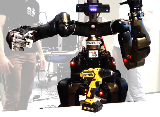
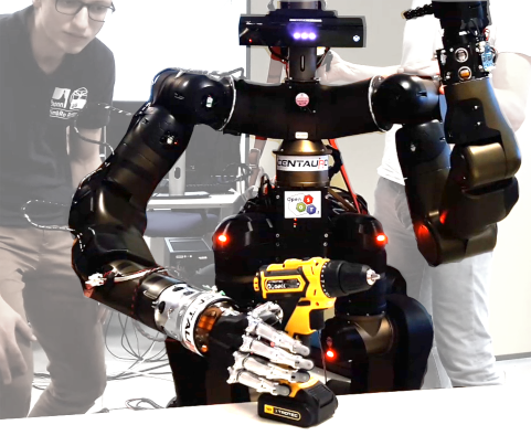
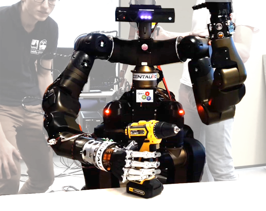
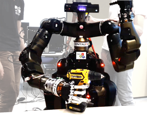
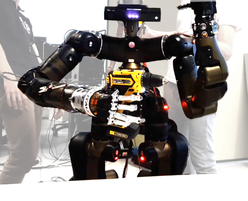
Our method was also tested in real-robot experiments. We created only one latent transformation model for the drill category using all the available meshes plus the canonical model. The observed object was inferred from one single view captured by the Kinect v2 sensor [29]. The tests were carried out on two different platforms: a UR10 arm and the CENTAURO robot. The hand was controlled by a PID position-current cascade controller, such that the joint position controller defines the desired joint currents. The saturation values of the current controller together with the PID values of the position controller were set to provide a certain level of compliance which contributed mainly at the last stage of the grasping motion. Using the UR10 robotic arm, our method was able to grasp two different drills twice without any failure. Similarly, with the CENTAURO robot, our approach grasped one instance of a drill twice without any failure (Fig. 8).
A video illustrating our approach is available online333http://www.ais.uni-bonn.de/videos/RA-L_2018_Rodriguez.
IV-A Discussion
Real experiments with two different robotic arms demonstrate that our method does not depend on the kinematics of the arm holding the hand. We assume however that the kinematics of the arm is able to reach 6D poses in its workspace. Our method is also agnostic to the robotic hand; a canonical grasping motion that is suitable to the hand is the only requirement for applicability.
Most of the grasping motions that failed exhibited a high deviation with respect to the canonical control poses which indicates a large variance in the learned transfer model. This suggests a need for more sample-efficient inference methods and the need for more training data.
V Conclusion
In this paper, we proposed a new approach of transferring grasping skills between objects within a category that is based on the knowledge aggregation of different training samples into a canonical model. Thanks to the learned latent shape space, our method is capable of completing missing or occluded object surfaces from partial views. Our method was able to transfer grasping skills with real robotic platforms from experiences collected only in simulation. This demonstrates the feasibility regarding the available sensory data (single-view point clouds) and runtime of our approach.
For future work, we want to consider more complex categories that impose higher variations in the joint configuration of the hand. So, more dimensionality reduction will be expected. As we realized the reduced number of training samples limits the presented approach, we start looking into automatic generation of plausible meshes from the canonical model. We also want to explore variants of the CPD algorithm in order to speed our current implementation. Finally, we would like also to exploit additional sensory modalities such as joint currents and force-torque sensors.
References
- Rodriguez et al. [2018] D. Rodriguez, C. Cogswell, S. Koo, and S. Behnke, “Transferring grasping skills to novel instances by latent space non-rigid registration,” in IEEE International Conference on Robotics and Automation (ICRA), 2018.
- Lévy et al. [2002] B. Lévy, S. Petitjean, N. Ray, and J. Maillot, “Least squares conformal maps for automatic texture atlas generation,” in ACM Transactions on Graphics (TOG), vol. 21, no. 3, 2002, pp. 362–371.
- [3] Y. Zeng, C. Wang, Y. Wang, X. Gu, D. Samaras, and N. Paragios, “Dense non-rigid surface registration using high-order graph matching,” in Computer Vision and Pattern Recognition (CVPR), 2010 IEEE Conference on, pp. 382–389.
- Kim et al. [2011] V. G. Kim, Y. Lipman, and T. Funkhouser, “Blended intrinsic maps,” in ACM Transactions on Graphics (TOG), vol. 30, no. 4, 2011, p. 79.
- Bronstein et al. [2006] A. M. Bronstein, M. M. Bronstein, and R. Kimmel, “Efficient computation of isometry-invariant distances between surfaces,” SIAM Journal on Scientific Computing, vol. 28, no. 5, pp. 1812–1836, 2006.
- [6] A. Tevs, M. Bokeloh, M. Wand, A. Schilling, and H.-P. Seidel, “Isometric registration of ambiguous and partial data,” in Computer Vision and Pattern Recognition (CVPR), 2009 IEEE Conference on, pp. 1185–1192.
- Ovsjanikov et al. [2010] M. Ovsjanikov, Q. Mérigot, F. Mémoli, and L. Guibas, “One point isometric matching with the heat kernel,” in Computer Graphics Forum, vol. 29, no. 5. Wiley Online Library, 2010, pp. 1555–1564.
- Allen et al. [2003] B. Allen, B. Curless, and Z. Popović, “The space of human body shapes: reconstruction and parameterization from range scans,” in ACM Transactions on Graphics (TOG), vol. 22, no. 3, 2003, pp. 587–594.
- Brown and Rusinkiewicz [2007] B. J. Brown and S. Rusinkiewicz, “Global non-rigid alignment of 3-d scans,” in ACM Transactions on Graphics (TOG), vol. 26, no. 3, 2007, p. 21.
- Hahnel et al. [2003] D. Hahnel, S. Thrun, and W. Burgard, “An extension of the ICP algorithm for modeling nonrigid objects with mobile robots,” in 18th International Joint Conference on Artificial Intelligence (IJCAI), 2003, pp. 915–920.
- Myronenko and Song [2010] A. Myronenko and X. Song, “Point set registration: Coherent point drift,” IEEE Transactions on Pattern Analysis and Machine Intelligence (PAMI), vol. 32, no. 12, pp. 2262–2275, 2010.
- Li et al. [2009] H. Li, B. Adams, L. J. Guibas, and M. Pauly, “Robust single-view geometry and motion reconstruction,” in ACM Transactions on Graphics (TOG), vol. 28, no. 5, 2009, p. 175.
- Süßmuth et al. [2008] J. Süßmuth, M. Winter, and G. Greiner, “Reconstructing animated meshes from time-varying point clouds,” in Computer Graphics Forum, vol. 27, no. 5. Wiley Online Library, 2008, pp. 1469–1476.
- Wand et al. [2009] M. Wand, B. Adams, M. Ovsjanikov, A. Berner, M. Bokeloh, P. Jenke, L. Guibas, H.-P. Seidel, and A. Schilling, “Efficient reconstruction of nonrigid shape and motion from real-time 3D scanner data,” ACM Transactions on Graphics (TOG), vol. 28, no. 2, p. 15, 2009.
- Newcombe et al. [2015] R. A. Newcombe, D. Fox, and S. M. Seitz, “Dynamicfusion: Reconstruction and tracking of non-rigid scenes in real-time,” in IEEE Conference on Computer Vision and Pattern Recognition (CVPR), 2015, pp. 343–352.
- Zollhöfer et al. [2014] M. Zollhöfer, M. Nießner, S. Izadi, C. Rehmann, C. Zach, M. Fisher, C. Wu, A. Fitzgibbon, C. Loop, C. Theobalt et al., “Real-time non-rigid reconstruction using an RGB-D camera,” ACM Transactions on Graphics (TOG), vol. 33, no. 4, p. 156, 2014.
- Hasler et al. [2009] N. Hasler, C. Stoll, M. Sunkel, B. Rosenhahn, and H.-P. Seidel, “A statistical model of human pose and body shape,” in Computer Graphics Forum, vol. 28, no. 2. Wiley Online Library, 2009, pp. 337–346.
- Burghard et al. [2013] O. Burghard, A. Berner, M. Wand, N. Mitra, H.-P. Seidel, and R. Klein, “Compact part-based shape spaces for dense correspondences,” CoRR, vol. abs/1311.7535, 2013.
- Engelmann et al. [2016] F. Engelmann, J. Stückler, and B. Leibe, “Joint object pose estimation and shape reconstruction in urban street scenes using 3D shape priors,” in German Conference on Pattern Recognition (GCPR), 2016, pp. 219–230.
- Vahrenkamp et al. [2016] N. Vahrenkamp, L. Westkamp, N. Yamanobe, E. E. Aksoy, and T. Asfour, “Part-based grasp planning for familiar objects,” in 16th IEEE-RAS International Conference on Humanoid Robots (Humanoids), 2016, pp. 919–925.
- [21] F. Ficuciello, D. Zaccara, and B. Siciliano, “Synergy-based policy improvement with path integrals for anthropomorphic hands,” in 2016 IEEE/RSJ International Conference on Intelligent Robots and Systems (IROS), pp. 1940–1945.
- [22] T. Stouraitis, U. Hillenbrand, and M. A. Roa, “Functional power grasps transferred through warping and replanning,” in 2015 IEEE International Conference on Robotics and Automation (ICRA), pp. 4933–4940.
- Hillenbrand and Roa [2012] U. Hillenbrand and M. A. Roa, “Transferring functional grasps through contact warping and local replanning,” in IEEE/RSJ International Conference on Intelligent Robots and Systems (IROS), 2012, pp. 2963–2970.
- Amor et al. [2012] H. B. Amor, O. Kroemer, U. Hillenbrand, G. Neumann, and J. Peters, “Generalization of human grasping for multi-fingered robot hands,” in IEEE/RSJ International Conference on Intelligent Robots and Systems (IROS), 2012, pp. 2043–2050.
- Stueckler et al. [2011] J. Stueckler, R. Steffens, D. Holz, and S. Behnke, “Real-time 3D perception and efficient grasp planning for everyday manipulation tasks.” in European Conference on Mobile Robots (ECMR), 2011, pp. 177–182.
- Yuille and Grzywacz [1988] A. L. Yuille and N. M. Grzywacz, “The motion coherence theory,” in Computer Vision, 2nd International Conference on (ICCV). IEEE, 1988, pp. 344–353.
- Shoemake [1992] K. Shoemake, “Uniform random rotations,” in Graphics Gems. Morgan Kaufmann, 1992, pp. 124–132.
- [28] A. E. Khoury, F. Lamiraux, and M. Taix, “Optimal motion planning for humanoid robots,” in 2013 IEEE International Conference on Robotics and Automation (ICRA), pp. 3136–3141.
- Fankhauser et al. [2015] P. Fankhauser, M. Bloesch, D. Rodriguez, R. Kaestner, M. Hutter, and R. Siegwart, “Kinect v2 for mobile robot navigation: Evaluation and modeling,” in International Conference on Advanced Robotics (ICAR), 2015, pp. 388–394.