Atomic-scale interaction of a crack and an infiltrating fluid
Abstract
In this work we investigate the Orowan hypothesis, that decreases in surface energy due to surface adsorbates lead directly to lowered fracture toughness, at an atomic/molecular level. We employ a Lennard-Jones system with a slit crack and an infiltrating fluid, nominally with gold-water properties, and explore steric effects by varying the soft radius of fluid particles and the influence of surface energy/hydrophobicity via the solid-fluid binding energy. Using previously developed methods, we employ the -integral to quantify the sensitivity of fracture toughness to the influence of the fluid on the crack tip, and exploit dimensionless scaling to discover universal trends in behavior.
I Introduction
Environmental influences, such as metal oxidation, salt-water corrosion, and fracking [1, 2, 3, 4, 5, 6], on fracture are ubiquitous in engineered and natural environments. Even without significant and complex chemistry, it is widely understood that the cleavage behavior of cracks is controlled by atomic forces and that the characteristic dimensions of crack tips are on the scale of fluid molecules. A basic tenet of fracture mechanics and propagation is that the fracture toughness of brittle materials is directly related to the energetic cost of forming new surfaces. In an early development of fracture mechanics, Orowan [7] postulated that the decrease in surface energy due to adsorption of environmental species would decrease effective fracture toughness. The manifestation of surface energy can involve complex phenomenon at the atomic level, e.g. surface reconstructions [8] and hydroxylation [9]. Also, the access of fluid to confined spaces like the crack tip is governed by capillary forces, fluid surface tension, and solid-fluid adhesion, all of which have a collective molecular origin.
The interplay of an infiltrating fluid with a crack can be complex. In fact, Michalske and Freiman [10] proposed a multistep process of bond breaking in cracked silica exposed to water where, initially, water assists with silica bond breaking, and the end-state energy is affected by surface hydroxylation. Furthermore, Fisk and Michalske [11] experimentally demonstrated that surface adsorption is an important aspect of chemically assisted fracture. Michalske et al. [12] also presented experimental evidence of steric exclusion of reactive species by the atomic dimensions of the crack tip. See Chap. 5 of Lawn et al. [13] for a detailed discussion of chemical effects on fracture.
In this study, we employ a Lennard-Jones (LJ) model of a crack infiltrated by a fluid together with dimensionless scaling to remove some of the complexities, e.g. surface reconstruction, multi-step chemical reactions and multiple pathways, that obscure what we assume to be the main contributors to fracture toughness: surface energy, steric considerations and fluid pressure.
II Theory
Here, we briefly review both the theory of configurational forces that connects the -integral to fracture toughness, and the linear elastic solutions for a perfect slit crack with a fluid at pressure.
The -integral is the generalized force energy-conjugate to the generalized displacement defined by the crack tip propagation. This energy conjugacy is based on the potential energy of an elastic body with a pre-existing crack and accounts for configuration changes due to crack propagation which changes reference configuration of the elastic body. (The full derivation is subtle, refer to Ref. [14] and the classical references therein.) The key is that the potential energy exhibits an explicit dependence on the location of the crack and hence the reference positions , and the derivative of the potential energy with respect to the explicit dependence on is identified with the divergence of the Eshelby stress which is composed of the free energy density , the deformation gradient , and the (first Piola-Kirchhoff) stress fields. Here, is the motion of the body. The -integral is defined as the divergence of the Eshelby stress,
| (1) |
in a region enclosed by with outward normal .
Linear elastic fracture mechanics (LEFM) provides an analytical solution for tensile (mode I) loading of a semi-infinite slit crack. The in-plane displacement field is:
| (2) | ||||
in terms of the shear modulus , (with being Poisson’s ratio), the in-plane polar coordinates , and the Cartesian coordinate vectors and . With this plane strain solution, Eq. (1) reduces to where . The critical value , where is the surface energy, is associated with the energetic cost of creating new surfaces along the crack. Particularly relevant to the influence of an infiltrating fluid on fracture, pressure on the crack faces augments -loading (Eq. (2)) by , where is the extent of pressure loading starting from the crack tip [15, Sec. 3.7]. External pressure does not change the intrinsic toughness of the material; however, with pressure, the apparent becomes where remains the scaling in the mechanical loading Eq. (2).
III Method
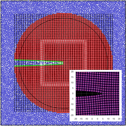
To model a solid-fluid system with a single slit crack (refer to Fig. 1), we employ an atomistic gold-like face-centered cubic (FCC) solid and a water-like simple particle fluid. The interatomic interactions are given by the commonly-used Lennard-Jones repulsive-attractive potential:
| (3) |
where is the distance between a pair of atoms/particles of species and . The potential starts from 0 at , decreases gradually to a well at and then steeply rises. It has two parameters: , which determines energy well depth, and , which determines the (soft) radius of the atoms. For computational efficiency, the interaction potential is truncated at a specified radius, . These parameters are specified in Table 1.
We fix the solid parameters, and , to those of a model of (brittle) Au from previous studies [16, 17]. This model has a lattice constant =4.08 Å, a Youngs modulus =271.95 GPa, a Poisson’s ratio =0.361437, and a (dry) surface energy =0.159949 eV/Å2. The fluid self-interaction energy is fixed to that of the SPC water model [18] (other models have similar values [19]). The size of the fluid particles and their attraction to the solid surfaces are varied to explore steric and hydrophobicity/surface energy effects. These physical attributes are controlled by and , respectively and independently. In particular, for , the fluid is hydrophobic with respect to the solid’s surface, i.e. it will preferentially adhere to itself; for , it is hydrophilic; and, for , it is reactive, in that a solid atom will bind to fluid particles in preference to other solid atoms. Also, if (estimated from the inset of Fig. 1), the fluid particles are unlikely to access the exposed interstitial sites of the solid. In addition to and , we use the standard LJ non-dimensionalization, e.g. for the fluid pressure and for the fluid density . The LJ phase diagram (see Fig. 3 in Ref. [20], for example) puts constraints on how the parameters can be varied and have the solid and liquid components remain so. For widest range of pressures where the fluid component remains liquid, we set the system temperature at and restrict the density to the range .
| [Å] | [eV] | [Å] |
|---|---|---|
| 2.59814680 | 0.72427859 | |
| 0.00673893 | ||
To construct the atomistic crack with infiltrating fluid shown in Fig. 1, we created an FCC lattice in a cylindrical region and a fluid at a specific density outside this. The slit crack was created by deleting bonds across in the solid. To obtain the -integral as a function of -loading, , we first displace solid atoms in an outer annulus via Eq. (2) with a -load increment . These atoms are fixed and the remainder are allowed to move. After an initial energy minimization, we simulated isothermal (Nosé-Hoover) dynamics for 40 ps, at , to accelerate diffusion and allow the fluid to infiltrate crack in a timely fashion, then another 40 ps, to ramp down to , and lastly 40 ps at . Finally, we quench the solid component of the system to connect to previous results based on energy minimization [16, 14] and the mechanical properties of the solid. From these atomic configurations we obtain the necessary continuum fields via a Irving-Kirkwood/Hardy procedure described in full in Ref. [21, 16, 14]. To insure we sufficiently sample the degenerate fluid and surface states, we report the averages from 200 replica systems.
IV Results
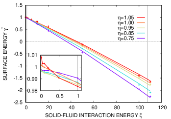
A number of preliminary property calculations were necessary. Since we vary the fluid particle size and want to control the pressure, we estimated the pressure equation-of-state (EOS), , assuming simple fluid behavior at fixed temperature . We fit isothermal data to a power law to obtain a power-law for pressure as a function of density , where , and . With this EOS, we control pressure for various by adjusting the fluid density 111 Specifically, determined the number of fluid particle in the system. . Also, since the fracture toughness depends on the surface energy , we estimated via the usual method employing a periodic system with a solid slab and a contacting dense fluid. With reference to Fig. 2, for a hydrophobic fluid, , the surface energy is effectively constant, and for it fits reasonably well to: . Note that (a) , i.e. proportional to packing density of the fluid, and (b) for a few layers of liquid (the thickness governed by the range of the potential ) crystallize on the surface of the solid, and (c) we neglect any pressure dependence of .
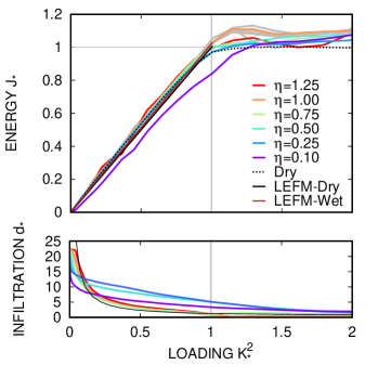
We now explore steric and pressure effects at the nominal surface energy. As expected from theory, in Fig. 3 is linear up to fracture (with a consistent slope across all cases ); and pressure has a only modest effect of increasing the slope of the effective curve since the fluid pressures are small compared to the solid’s elastic modulus (at the nominal pressure, , ). For the range of fluid sizes the curves are nearly identical to that calculated for the dry system; however, there are apparent changes in the critical and values at the extreme fluid particle sizes. For fluid particles greater than the interstitial size, , the calculated closest approach of the fluid particles to the crack tip compares well to the geometric expectation given by Eq. (2) and the (soft) radius of the fluid particles ( is the group of fluid particles and the crack tip is at the origin) 222 The continuum solution Eq. (2) gives , on . This leads to closest approach of a fluid particle to the crack tip for and otherwise, where is the radius of curvature of crack, and , are the soft radii of the fluid and solids atoms. . In fact, for these cases, (a) there is a slight increase in with , and (b) near , is constant until the crack opens sufficiently and this transition point depends on . For , the fluid particles can infiltrate the lattice and do so in preference to diffusing to the tip. This was observed directly and can be inferred from . For this infiltration is so pervasive (and not localized at the tip) as to soften the lattice and toughen the material relative to the pure solid, as is apparent from the data. For , both the critical and are significantly higher than in the dry case. For , the critical and are higher than in the dry case but the critical less than in the case and yet the critical is higher. This trend does not correlate with the variation of with nor with .
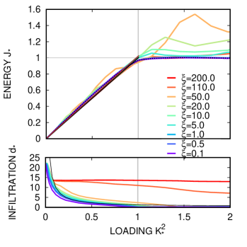
The changes in apparent fracture toughness with changing fluid:solid interactions are less subtle. Fig. 4 shows that if the fluid is hydrophobic () the fracture toughness is also unchanged, as expected, since the surface energy is effectively the same. On the other hand, as Fig. 2 demonstrates, the surface energy is reduced by hydrophilic fluids () and yet Fig. 4 clearly shows that both the critical and increase with . Our conjecture is that adsorbed fluid monolayers transmit the solid-fluid binding energy between the opposing crack faces at high . This is especially apparent at where the crack takes on a distinct cusp-like profile and the initial bump in the was observed to be an infiltration, not crack propagation, event. Generally, higher inhibits the infiltration of fluid into the crack (i.e. higher , with the extreme cases being where unstructured alloys of the solid and liquid species form obstructions that shield the crack tip from contact with the (reactive) fluid and is essentially coincident with the dry case.
V Discussion
Through atomistic simulation we found that the effects of a hydrophilic fluid can lead to a trend in fracture toughness that is contrary to Orowan’s hypothesis that toughness of brittle solids decreases with the decrease of surface energy due to adsorbed species. The effect was most pronounced at approximately five times the nominal solid-fluid interaction energy (above which the fluid reacts with the solid). We conjecture that without a direct mechanism for return of energy of adhesion to crack tip, the transmission of binding forces through atomically thin layers of fluid can dominate and create the observed trend. We found that for a reasonable range of parameters, steric effects were relatively minor, except for fluid particles small enough to infiltrate and soften the solid lattice. Of course, this may change under extreme fluid pressures. Lastly, we observed that highly reactive fluids can obstruct fluid access to the crack tip.
Acknowledgments
We are grateful for technical discussions with Jonathan A. Zimmerman. This work was supported by the LDRD program at Sandia National Laboratories, and its support is gratefully acknowledged. Sandia National Laboratories is a multimission laboratory managed and operated by National Technology and Engineering Solutions of Sandia, LLC., a wholly owned subsidiary of Honeywell International, Inc., for the U.S. Department of Energy’s National Nuclear Security Administration under contract DE-NA-0003525. The views expressed in the article do not necessarily represent the views of the U.S. Department of Energy or the United States Government.
References
- [1] Brian R Lawn, DB Marshall, and P Chantikul. Mechanics of strength-degrading contact flaws in silicon. Journal of Materials Science, 16(7):1769–1775, 1981.
- [2] MD Thouless and RF Cook. Stress-corrosion cracking in silicon. Applied physics letters, 56(20):1962–1964, 1990.
- [3] R Sawada. Influence of scribe damage on pits formed by immersion of Si in HF solution. Journal of applied physics, 60(1):401–405, 1986.
- [4] Chern P Chen and Martin H Leipold. Fracture toughness of silicon. American Ceramics Society Bulletin, 59:469–472, 1980.
- [5] B Wong and RJ Holbrook. Microindentation for fracture and stress-corrosion cracking studies in single-crystal silicon. Journal of the Electrochemical Society, 134(9):2254–2256, 1987.
- [6] Chris G Van de Walle, FR McFeely, and ST Pantelides. Fluorine-silicon reactions and the etching of crystalline silicon. In MRS Proceedings, volume 141, page 425. Cambridge Univ Press, 1988.
- [7] E Orowan. The fatigue of glass under stress. Nature, 154(3906):341, 1944.
- [8] AA Baski, SC Erwin, and LJ Whitman. The structure of silicon surfaces from (001) to (111). Surface Science, 392(1):69–85, 1997.
- [9] JM Rimsza, RE Jones, and LJ Criscenti. Surface structure and stability of partially hydroxylated silica surfaces. Langmuir, 33(15):3882–3891, 2017.
- [10] Terry A Michalske and Stephen W Freiman. A molecular interpretation of stress corrosion in silica. Nature, 295(5849):511, 1982.
- [11] GA Fisk and TA Michalske. Laser-based and thermal studies of stress corrosion in vitreous silica. Journal of applied physics, 58(7):2736–2741, 1985.
- [12] Terry A Michalske and Bruce C Bunker. Steric effects in stress corrosion fracture of glass. Journal of the American Ceramic Society, 70(10):780–784, 1987.
- [13] Brian R Lawn. Fracture of brittle solids. Cambridge university press, 1993.
- [14] RE Jones, JM Rimsza, and LJ Criscenti. An atomic-scale evaluation of the fracture toughness of silica glass. Journal of Physics: Condensed Matter, 30(24):245901, 2018.
- [15] Hiroshi Tada, Paul C Paris, and George R Irwin. The stress analysis of cracks. Del Research Corporation, Hellertown, PA, 1973.
- [16] Reese E Jones and Jonathan A Zimmerman. The construction and application of an atomistic J-integral via Hardy estimates of continuum fields. Journal of the Mechanics and Physics of Solids, 58(9):1318–1337, 2010.
- [17] Reese E Jones, Jonathan A Zimmerman, Jay Oswald, and Ted Belytschko. An atomistic J-integral at finite temperature based on Hardy estimates of continuum fields. Journal of Physics: Condensed Matter, 23(1):015002, 2010.
- [18] Herman JC Berendsen, James PM Postma, Wilfred F van Gunsteren, and Jan Hermans. Interaction models for water in relation to protein hydration. In Intermolecular forces, pages 331–342. Springer, 1981.
- [19] William L Jorgensen, Jayaraman Chandrasekhar, Jeffry D Madura, Roger W Impey, and Michael L Klein. Comparison of simple potential functions for simulating liquid water. The Journal of Chemical Physics, 79(2):926–935, 1983.
- [20] Shiang-Tai Lin, Mario Blanco, and William A Goddard III. The two-phase model for calculating thermodynamic properties of liquids from molecular dynamics: Validation for the phase diagram of Lennard-Jones fluids. The Journal of Chemical Physics, 119(22):11792–11805, 2003.
- [21] Jonathan A Zimmerman, Reese E Jones, and Jeremy A Templeton. A material frame approach for evaluating continuum variables in atomistic simulations. Journal of Computational Physics, 229(6):2364–2389, 2010.
- [22] Specifically, .
- [23] The continuum solution Eq.\tmspace+.1667em(2) gives , on . This leads to closest approach of a fluid particle to the crack tip for and otherwise, where is the radius of curvature of crack, and , are the soft radii of the fluid and solids atoms.