All-optical magnetization switching by two-frequency pulses using the plasmon-induced inverse Faraday effect in a magneto-plasmonic structure
Abstract
In this Letter we study the generation of quasi-static magnetic fields by the plasmon-induced inverse Faraday effect and propose a magneto-optical waveguide structure for achieving magnetization switching at sub-ps time in a nano-confined magneto-optical structure. In particular we show that the direction of the generated quasi-static field in a magneto-optical dielectric cavity side-coupled to a metal-insulator-metal (MIM) waveguide depends sensitively on the wavelength of the surface plasmon polaritions (SPP). This phenomenon could open up a new energy-efficient ultrafast method for nano-confined all-optical magnetization switching by two-frequency pulses.
pacs:
75.78.jp, 75.60.Jk, 73.20.Mf, 78.20.LsIn a magneto-optical material irradiated by circularly polarized light an effective quasi-static magnetic field along the wave vector is induced. This phenomenon called the inverse Faraday effect (IFE) Pitaevskii (1961); der Ziel et al. (1965) is a counterpart of the Faraday effect which rotates the linear polarization of light propagating through a magneto-optical material in the presence of a magnetic field. Left- and right-handed circular polarized light induce the magnetization with opposite direction and the magnetization vanishes for linearly polarized waves. Several theoretical approaches have been developed to provide physical insight on the effect (see e.g. Kurkin et al. (2008); Popova et al. (2012); Qaiumzadeh et al. (2013); Battiato et al. (2014); Berritta et al. (2016)).
Recently, the inverse Faraday effect has attracted much attention because of its potential impact for ultrafast all-optical switching of magnetization in thin magnetic films induced by ultrafast pulses Beaurepaire et al. (1996); Stanciu et al. (2007); Kirilyuk et al. (2010) which opens the possibility for magnetic data storage with unprecedented speed. The influence of the helicity of the circular polarized laser pulses in magnetization switching has been attributed to the IFF but in later studies depending on the magnetic material other explanations has been proposed which remain up to now in investigation. Recent studied ferromagnetic thin films indicate the basic role of the IFE in helicity-depending magnetization in these materials Cornelissen et al. (2016); John et al. (2017). However, the spot size of the input pulses limit the density memory modules and sets limits for the lowest requested pulse energy. Moreover, all-optical magnetic switching by free space circularly polarized light is not fully waveguide-integrated and not compatible with highly integrated photonic circuits.
In order to improve the recording density a method is requested which allow sub-wavelength spatial resolution of light pulses for magnetic recording. The IFE in plasmonic structures illuminated by free space circularly polarized light can be significantly amplified by the plasmon field enhancement caused by localized surface plasmons Belotelov et al. (2010); Hamidi et al. (2015); von Korff Schmising et al. (2015); Dutta et al. (2017). Besides laser pulses has been focused by using plasmonic nanoantena structures to achieve nanoscale confinement of all-optical magnetization switching Stipe et al. (2010); Liu et al. (2015); Guyader et al. (2015).
In this paper, we study a modified version of nanoscale IFE in which instead of free space circular polarized optical pulses free running surface plasmon polaritons (SPPs) induce a magnetic field. SPPs exhibit a longitudinal component of the electric field, therefore the vector product of E and its complex conjugate E* do not vanishes. This means that even for linearly polarized input beams a magnetization can be induced by running SPPs generated by the incident p-polarized light pulses, but the plasmons are not circularly polarized in the customary sense. Recently, based on this phenomenon an IFE-related third-order nonlinearity of surface plasmon polaritons was predicted Im et al. (2017). By using the plasmon-induced IFE we propose and study a magneto-optical structure consisting of a magneto-optical cavity side-coupled to a metal-insulator-metal (MIM) waveguide and demonstrate the possibility for all-optical magnetic switching by two-frequency sub-ps pulses.
The inverse Faraday effect (IFE) can be described for a lossless opto-magnetic material by the thermodynamical potential where is the electric field of the light with frequency . Therefore for isotropic materials we find
| (1) |
where is the magneto-optical susceptibility. To achieve a high magnitude of the effective magnetic field , a material with large magneto-optical susceptibility as well as a value of inside the material as large as possible are requested. For linearly polarized light, . For circularly polarized light propagating along the -axis we have with
| (2) |
where the sign of is dependent on the helicity of the circularly polarized light.
Light cannot penetrate into a thin metallic layer, but under appropriate conditions (as e.g. by using the Kretschman configuration for p-polarized light or a grating structure) surface plasmon-polaritons (SPP) can be excited moving along the surface. SPPs exhibit a longitudinal component of the electric field, therefore the polarization-depending value of do not vanishes. This means that even for linearly polarized input beams a magnetization can be induced by plasmons, but the plasmons are not circularly polarized in the customary sense. Let us calculate the quasi-static magnetic field induced by the longitudinal polarized SPP. According to Eq. (1) the magnetic field is determined by the entity where is defined by
| (3) |
Here the wavevector is along the -axis and the electric field vector is in the - plane. If we substitute the expression for the electric field distribution of a single metal-dielectric interface Maier (2007) in Eq. (3) we find
| (4) |
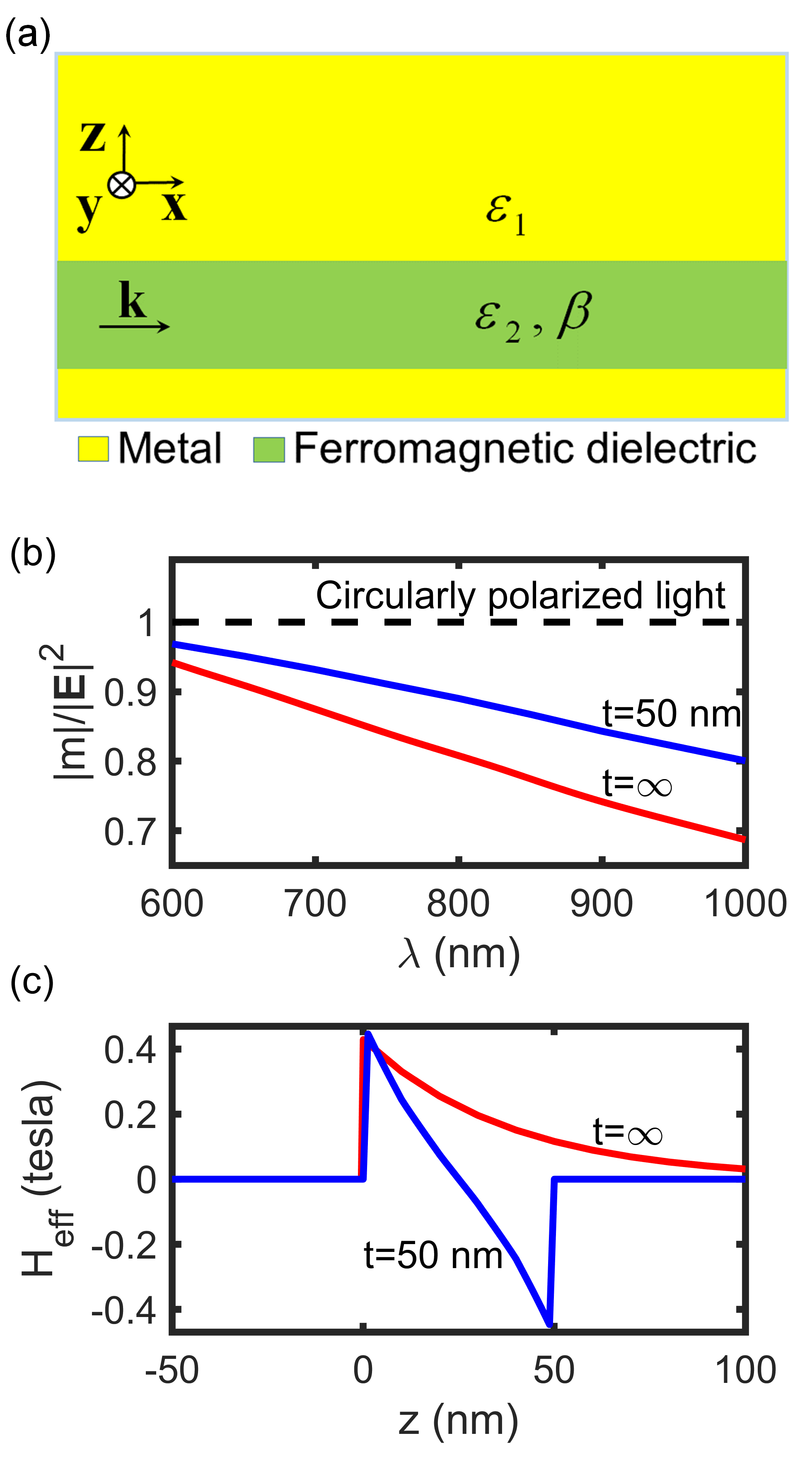
where and are the permittivities of the dielectric and the metal, respectively. For a dielectric =1 and For a metal =-1. The value of in a single metal-dielectric interface in dependence on the wavelength is shown in the red curve of Fig. 1(b). Near the plasmon resonance , which is close to the case of excitation by free space circularly polarized light. Away from the resonance, this parameter is reduced, but still maintaining a moderate value of 0.5. In Fig. 1(b) and (c) a magneto-optical metal-insulator-metal (MIM) waveguide as shown in Fig. 1(a) is studied with a dielectric layer composed of Bi-substituted iron garnet (BIG). In Fig. 1(b) the value of in dependence on the wavelength is shown. As seen this parameter increases with the reduction of the thickness of the dielectric layer. In Fig. 1(c) the transverse distribution of the IFE-induced quasi-static magnetic field is presented where the induced magnetic field is 0.4 tesla for an incident mode power of 10 W/m and its direction on the downside interface is opposite to that in the upside interface.
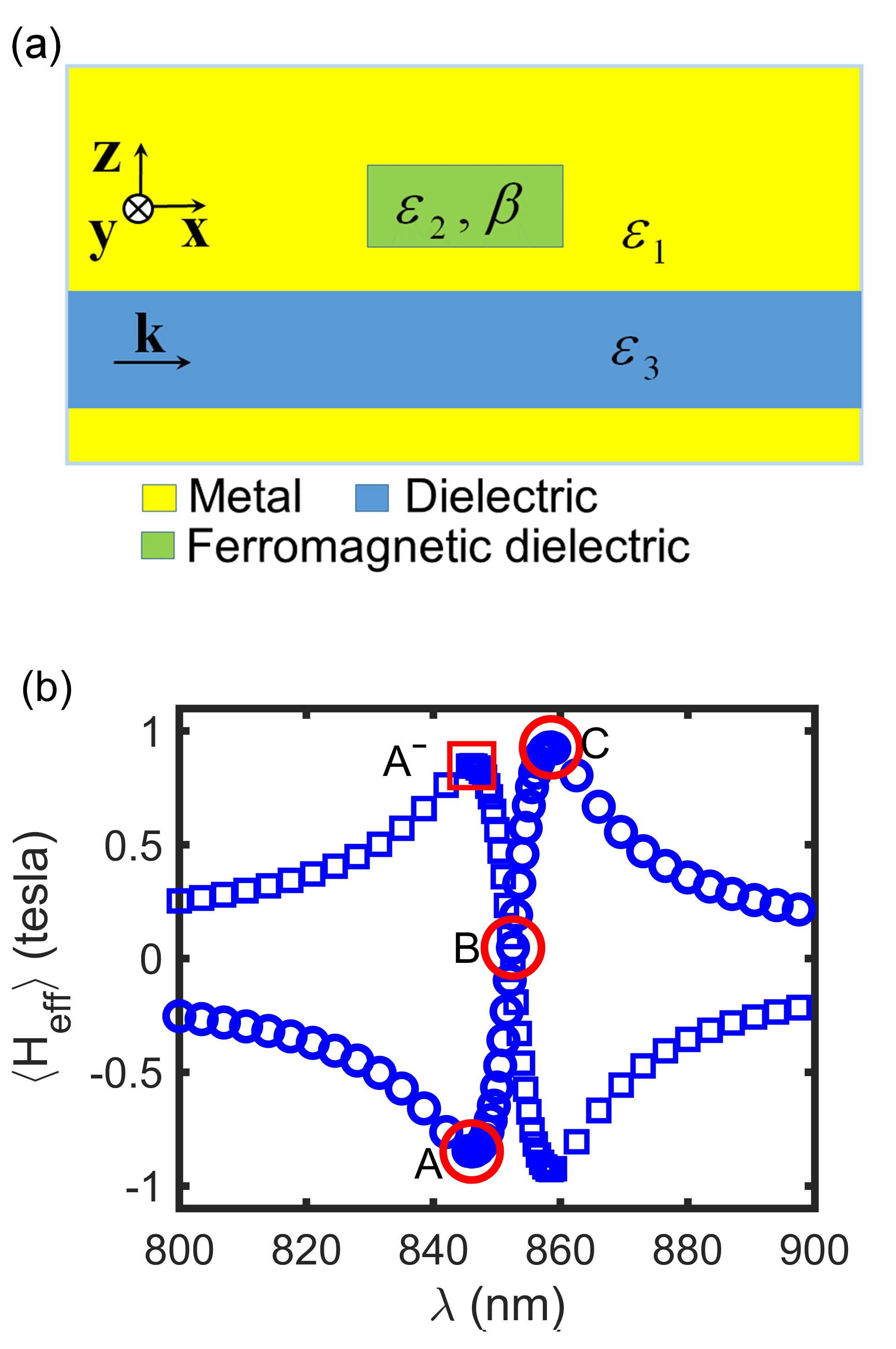
Based on the plasmon-induced IFE we now study magnetization switching by a magneto-optical cavity side-coupled to a MIM waveguide as shown in Fig. 2(a). The average effective magnetic field denotes the average value over the magneto-optical cavity (the green part of Fig. 2(a)). is sensitive to the wavelength near the resonance and perceives a sign change (the points A and C of Fig. 2(b)). It becomes zero at the exact resonance (the point B of Fig. 2(b)). The sign of is reversed for backward propagating SPPs (the point A- of Fig. 2(b)).
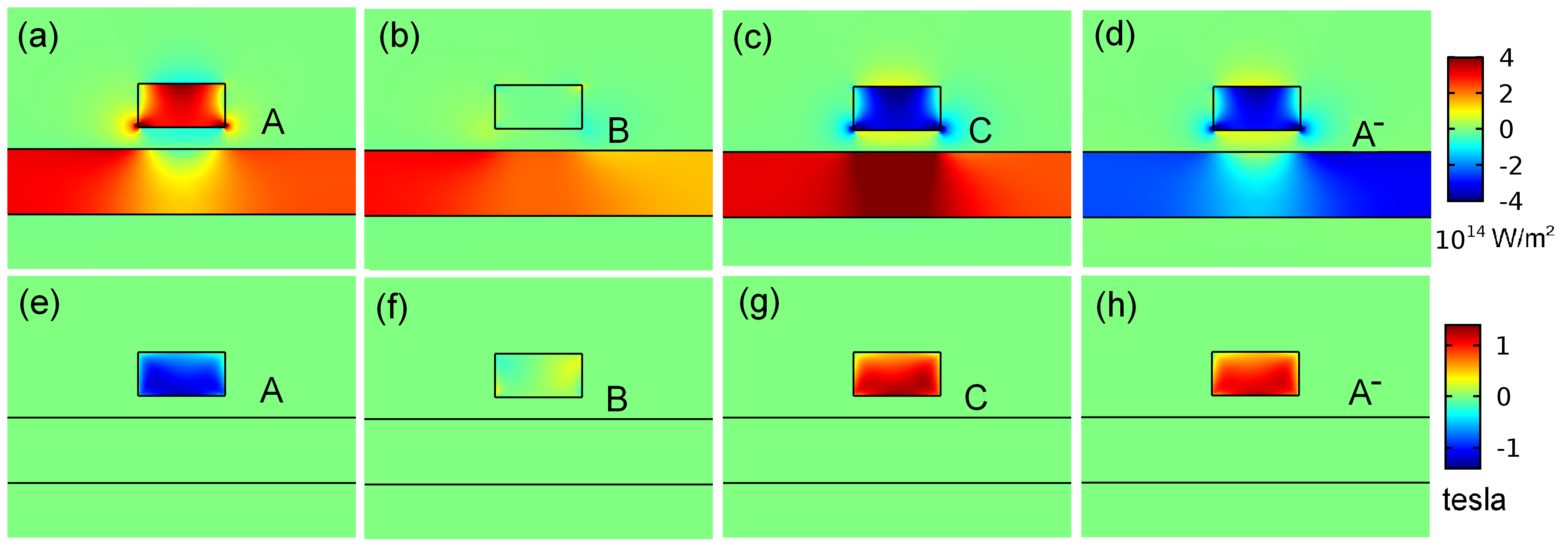
Fig. 3 shows the near field distribution of the x-component of pointing vector ((a), (b), (c) and (d)) and ((e), (f), (g) and (h)) for the points A, B, C and A- of Fig. 2(b) calculated by the numerical solution of Maxwell’s equations. At the point A, the effective magnetic field has a negative value of 1 tesla inside the magneto-optical cavity for SPPs moving into the direction along the x-axis. At the points C and A-, the effective magnetic field has the same value of 1 tesla, but the energy flow is into the reverse direction. At the point B, both the effective magnetic field and the energy flow disappear because of the perfect standing wave mode incide the cavity at the exact resonance.
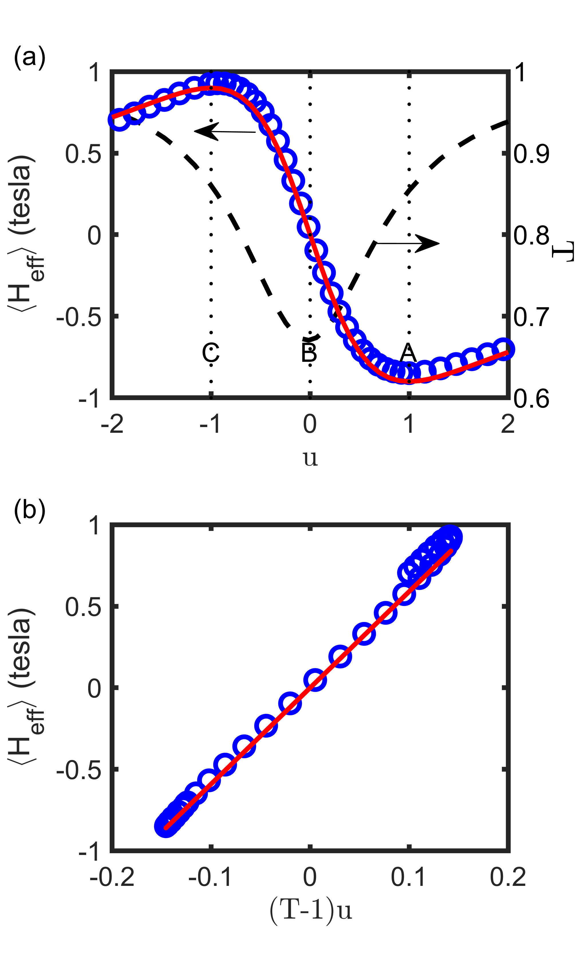
The resonance of has a Lorentzian-like profile which can be approximated by
| (5) |
Here is the decay rate, the resonance frequency and a coefficient. On the other hand, the transmission through the magneto-optical structure is described by Im et al. (2016). The results by Eq. (5) (the red curve of Fig. 4(a)) well agree with the results of (the blue circles of Fig. 4(a)) obtained by the numerical solution of Maxwell’s equations. has been calculated from the numerical results for the transmission (the black dashed curve). As shown in Fig. 4(a), has a positive maximum value at , a negative minimum value at and is zero at . The linear relationship between the value of and is clearly demonstrated as shown in Fig. 4(b) by the numerical results of the solutions of Maxwell’s equations. This suggests that the plasmon-induced magnetic field in the magneto-optical cavity can be indirectly measured by measuring the transmission of the waveguide plasmon.
Let us estimate the order of energy consumption needed for reversable binary magnetic recording. We note that magnetization of BIG saturates for 0.15 tesla (see the Methods of Ref. Davoyan and Engheta (2014)). From Fig. 2 and 3 one predicts that a power of 1.5 W/m of the incident pulses can produce an effective magnetic field on the order of 0.15 tesla. The needed energy is roughly estimated as , where is the lateral size of the waveguide in the y-axis direction and the full-width at half maximum (FWHM) of the incident pulse. We take 1 m and 100 fs under the assumption that a lateral size on the order of 1 m does not induce noticeable deterioration to the device performance Cai et al. (2009) and the magnetization switching can be achieved on a time scale of 100 fs Vahaplar et al. (2012). Thus the energy consumption is on the order of 100 fJ/bit. We remind that a laser pulse fluence on the order of 1 mJ/cm2 Dutta et al. (2017) is needed to induce an effective magnetic field on the order of 0.1 tesla inside a ferromagnetic film illuminated by circularly polarized light beam with a beam diameter of tens of m, thus the needed energy for the traditional IFE is on the order of 10 nJ/bit. This rough estimation shows that the IFE induced by quasi-resonance in a magneto-optical cavity side-coupled to a MIM waveguide requires several orders of magnitude smaller pulse energy for the generation of a magnetic field of 0.1 tesla compared with the traditional IFE. This significant reduction is attributed to the strong confinement in the MIM waveguide and the cavity modes.
In conclusion, we investigated a modified version of the inverse Faraday effect induced by running SPPs with a longitudinal component of the electric field vector in magneto-optical waveguides. We calculated the effective magnetic field in a metal-insulator-metal (MIM) waveguide with a dielectric magneto-optical layer composed of Bi-substituted iron garnet (BIG) and found that its direction on the upside interface is opposite to that of the downside interface. Based on the SPP-induced IFE we investigated magnetization switching by using a magneto-optical cavity side-coupled to a MIM waveguide. The SPP-induced magnetization inside the magneto-optical cavity has a Lorentzian-like resonance profile. Magnetization reversal can be achieved by using two-frequency pulses with opposite frequency detuning from the resonance so that the detuning parameter has a value 1 or -1. This approach for nano-scale magnetization switching is energy-efficient, fully waveguide-integrated, compatible with integrated nano-photonic circuits and could be promising for all-optical magnetic recording in highly integrated photonic circuits.
References
- Pitaevskii (1961) L. P. Pitaevskii, Sov. Phys. JETP 12, 1008 (1961).
- der Ziel et al. (1965) J. P. V. der Ziel, P. S. Pershan, and L. D. Malmstrom, Phys. Rev. Lett. 15, 190 (1965).
- Kurkin et al. (2008) M. I. Kurkin, N. B. Bakulina, and R. V. Pisarev, Phys. Rev. B 78, 134430 (2008).
- Popova et al. (2012) D. Popova, A. Bringer, and S. Blügel, Phys. Rev. B 85, 094419 (2012).
- Qaiumzadeh et al. (2013) A. Qaiumzadeh, G. E. W. Bauer, and A. Brataas, Phys. Rev. B 88, 064416 (2013).
- Battiato et al. (2014) M. Battiato, G. Barbalinardo, and P. M. Oppeneer, Nat. Commun. 89, 014413 (2014).
- Berritta et al. (2016) M. Berritta, R. Mondal, K. Carva, and P. M. Oppeneer, Phys. Rev. Lett. 117, 137203 (2016).
- Beaurepaire et al. (1996) E. Beaurepaire, J.-C. Merle, A. Daunois, and J.-Y. Bigot, Phys. Rev. Lett. 76, 4250 (1996).
- Stanciu et al. (2007) C. D. Stanciu, F. Hansteen, A. V. Kimel, A. Tsukamoto, A. Itoh, A. Kirilyuk, and T. Rasing, Phys. Rev. Lett. 99, 047601 (2007).
- Kirilyuk et al. (2010) A. Kirilyuk, A. V. Kimel, and T. Rasing, Rev. Mod. Phys. 82, 2731 (2010).
- Cornelissen et al. (2016) T. D. Cornelissen, R. M. C. Castillo, and B. Koopmans, Appl. Phys. Lett 108, 142405 (2016).
- John et al. (2017) R. John, M. Berritta, D. Hinzke, C. Müller, T. Santos, H. Ulrichs, P. Nieves, J. Walowski, R. Mondal, O. Chubykalo-Fesenko, J. McCord, P. M. Oppeneer, U. Nowak, and M. Münzenberg, Sci. Rep. 17, 4114 (2017).
- Belotelov et al. (2010) V. I. Belotelov, E. A. Bezus, L. L. Doskolovich, A. N. Kalish, and A. K. Zvezdin, J. Phys.: Conf. Ser. 200, 092003 (2010).
- Hamidi et al. (2015) S. M. Hamidi, M. Razavinia, and M. M. Tehranchi, Optics Comm. 338, 240 (2015).
- von Korff Schmising et al. (2015) C. von Korff Schmising, M. Giovannella, D. Weder, S. Schaffert, J. Webb, and S. Eisebitt, New J. of Phys. 17, 033047 (2015).
- Dutta et al. (2017) A. Dutta, A. V. Kildishev, V. M. Shalaev, A. Boltasseva, and E. E. Marinero, Opt. Mater. Express 7, 4316 (2017).
- Stipe et al. (2010) B. C. Stipe, T. C. Strand, C. C. Poon, H. Balamane, T. D. Boone, J. A. Katine, J. L. Li, V. Rawat, H. Nemoto, A. Hirotsune, O. Hellwig, R. Ruiz, E. Dobisz, D. S. Kercher, N. Robertson, T. R. Albrecht, and B. D. Terris, Nat. Photonics 4, 484 (2010).
- Liu et al. (2015) T. Liu, T. Wang, A. H. Reid, M. Savoini, X. Wu, B. Koene, P. Granitzka, C. E. Graves, D. J. Higley, Z. Chen, G. Razinskas, M. Hantschmann, A. Scherz, J. Stohr, A.Tsukamoto, B. Hecht, A. V. Kimel, A. Kirilyuk, T. Rasing, and H. A. Durr, Nano Lett. 15(10), 6862 (2015).
- Guyader et al. (2015) L. L. Guyader, M. Savoini, S. E. Moussaoui, M. Buzzi, A. Tsukamoto, A. Itoh, A. Kirilyuk, T. Rasing, A. V. Kimel, and F. Nolting, Nat. Commun. 6, 5839 (2015).
- Im et al. (2017) S.-J. Im, C.-S. Ri, K.-S. Ho, and J. Herrmann, Phys. Rev. B 96, 165437 (2017).
- Johnson and Christy (1972) P. B. Johnson and R. W. Christy, Phys. Rev. B 6, 4370 (1972).
- Maier (2007) S. A. Maier, Plasmonics: Fundamentals and Applications (Springer, New York, 2007).
- Im et al. (2016) S.-J. Im, G.-S. Ho, D.-J. Yang, Z.-H. Hao, L. Zhou, N.-C. Kim, I.-G. Kim, and Q.-Q. Wang, Sci. Rep. 6, 18660 (2016).
- Davoyan and Engheta (2014) A. Davoyan and N. Engheta, Nat. Commun. 5, 5250 (2014).
- Cai et al. (2009) W. Cai, J. White, and M. Brongersma, Nano Lett. 9, 4403 (2009).
- Vahaplar et al. (2012) K. Vahaplar, A. M. Kalashnikova, A. V. Kimel, S. Gerlach, D. Hinzke, U. Nowak, R. Chantrell, A. Tsukamoto, A. Itoh, A. Kirilyuk, and T. Rasing, Phys. Rev. B 85, 104402 (2012).