Further author information: (Send correspondence to M. Crumrine)
M. Crumrine: E-mail: crumrine@umn.edu
BICEP Array cryostat and mount design
Abstract
Bicep Array is a cosmic microwave background (CMB) polarization experiment that will begin observing at the South Pole in early 2019. This experiment replaces the five Bicep2 style receivers that compose the Keck Array with four larger Bicep3 style receivers observing at six frequencies from 30 to 270GHz. The 95GHz and 150GHz receivers will continue to push the already deep Bicep/Keck CMB maps while the 30/40GHz and 220/270GHz receivers will constrain the synchrotron and galactic dust foregrounds respectively. Here we report on the design and performance of the Bicep Array instruments focusing on the mount and cryostat systems.
keywords:
Inflation, Gravitational Waves, Cosmology, BICEP, Keck Array, Polarization, BICEP Array1 INTRODUCTION
Precision measurements of the cosmic microwave background have significantly increased our understanding of the early universe. Beginning with the discovery of the CMB—providing the first evidence for a Big Bang origin to the universe[1, 2]—experimental cosmology has become an extremely active subfield of physics. Subsequently the development of the CDM cosmological model has seen tremendous success in its ability to accurately and self-consistently explain and predict observational data. The CDM model is, however, still incomplete and fails to explain the homogeneity and isotropy of our observable universe. These issues can be resolved by an extension to the model in which the universe undergoes a period of exponential expansion known as inflation just after the beginning[3]. Various models of inflation exist, many of which predict that such an event would have generated an observable gravitational wave background. Interaction between these inflationary gravitational waves (IGWs) and the primordial plasma would have produced a characteristic curl-like polarization signal colloquially referred to as “B-modes”. Measurement of this signal is generally characterized by the tensor to scalar ratio , which can also be used as a measure of the energy scale of inflation as well as to differentiate inflationary models.
Detection of the inflationary B-mode signal is complicated by the presence of other B-mode signals. At small angular scales, lensing of divergence-like CMB polarization can convert so called “E-modes” into B-modes through small angular remappings. Other sources of B-mode signal exist in our own galaxy. Polarized emission from galactic dust and galactic synchrotron radiation are the two dominant foregrounds in our own galaxy, each characterized by independent frequency and angular scale relations. Detection of any primordial B-mode signal requires observations at multiple frequencies to enable its separation from these foregrounds.
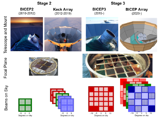
The Bicep/Keck experiments are a staged series of microwave telescopes that observe the CMB from the geographic South Pole and target degree-scale B-mode polarization. Each successive generation of telescopes builds upon the experience gained with the previous while simultaneously increasing sensitivity. A graphical progression from Bicep2 to Bicep Array is shown below in Fig. 1. Foreground signals exhibit strong frequency dependence which allows these components to be isolated from the IGW signal by observing the microwave sky across a range of frequencies. Keck Array consists of five Bicep2 style receivers[4, 5] with observations spread across four frequency bands (95, 150, 220, and 270 GHz). The combination of Bicep2 and Keck Array data has produced the tightest constraint on this signal to date of ( confidence)[6]. Bicep Array will build on the success of the Keck Array by deploying four Bicep3 style receivers[7], and expanding observations into two additional frequency bands at 30 and 40 GHz. Extrapolating from achieved performance, Bicep Array is projected to reach , either detecting the IGW signal or improving the constraint to ( confidence).
2 Cryostat Design
Bicep Array continues the successful design philosophy of the previous Bicep/Keck receivers. A 2 meter tall vacuum shell contains two nested stages with nominal operating temperatures of 50K and 4K which accommodate optical elements and shield a sub-Kelvin focal plane. The design of the sub-kelvin structure and focal plane can be found in Hui. et. al.[8], and Soliman. et. al.[9]. A cross section of the cryostat is shown in Fig. 2. The top section of the vacuum jacket houses the vacuum window and a stack of Zotefoam filters which reduce infrared loading onto the colder stages. More information on the performance of this filtering scheme can be found in J. Kang et. al.[10]. The use of low-conductivity structural supports keeps the interior stages sufficiently supported while conducting only a small amount of heat from the room temperature vacuum vessel. These supports are described in more detail in Sec. 3. The intermediate 50K stage serves as a radiation shield for the interior 4K stage. The lower of the 50K stage is wrapped with a -thick magnetic shield composed of Amuneal[11] A4K®. The top of this stage additionally accommodates an alumina filter to further reduce infrared loading onto the sub-Kelvin receiver. The 4K stage serves as a second radiation shield while also providing mounting interfaces for two alumina lenses and optical baffling.
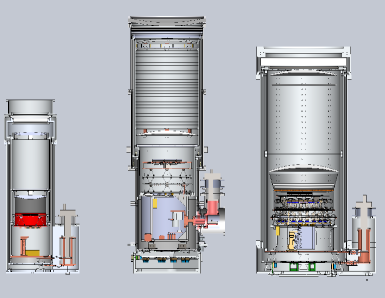
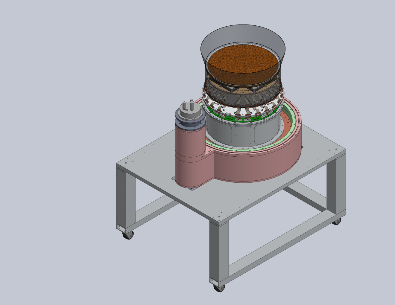
The cryostat design enables ease of access to the focal plane assembly without disturbing the majority of thermal joints or the back-end cabling. The cryostat disassembles by lifting off shells successively from the outside in, leaving behind a stand-along base which contains the sub-Kelvin focal plane assembly, readout electronics, and the cooling system as shown in Fig. 3. In this state, the focal plane and detector modules may be freely accessed for maintenance. Access to the pulse tube, heat straps, and readout cabling is provided by hatches on the bottom side of the vacuum shell and 50K bases. This scheme significantly reduces the time required for disassembly when accessing the focal plane and re-assembly afterwards by allowing critical thermal junctions and difficult part matings to remain undisrupted.
3 Thermal Architecture
The 50K and 4K radiation shields are cooled by the first and second stages of a Cryomech[12] PT415-RM Pulse Tube cooler respectively. This cryocooler is capable of maintaining a first stage temperature of K under a 40W load and a second stage temperature of K under a 1.5W load. The cooler of these two stages is required to maintain a sufficiently cold temperature to allow the operation of a three-stage helium sorption fridge which cools the sub-Kelvin focal plane assembly. The interior stages must therefore be well insulated in order to stay within the thermal budget. Various aspects of the thermal architecture are described below, Table 1 provides a numerical breakdown of the estimated thermal loading onto the cold stages.
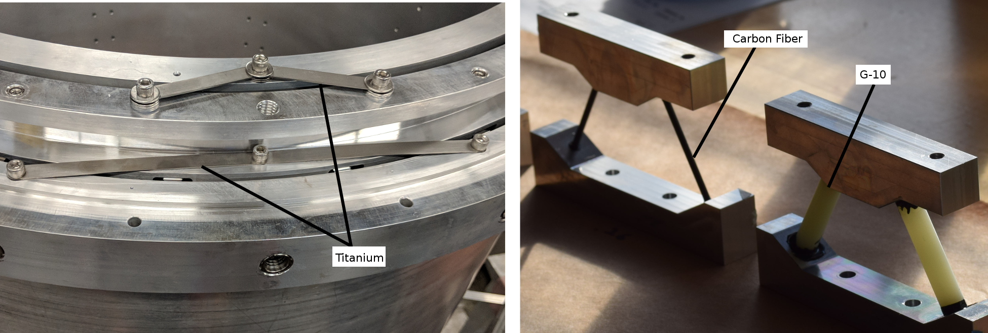
The radiation absorbed by the interior stages is reduced by the use of multi-layer insulation (MLI) wrapped around the outside of the 50K and 4K stages. These MLI blankets are composed of many aluminized Mylar® layers separated by polyester spacer layers. Where there is insufficient room for uncompressed insulation, we plan to use low emissivity aluminum tape on parallel faces to decrease the radiation absorbed by the lower temperature surface. A low thermal conductivity support system keeps the three stages thermally insulated from each other and provides structural support. The front end of each shell is constrained by thin Ti-Al-4V straps which allow flexing along the axial direction of the cryostat to absorb differential thermal contraction. At the back end, the 50K and 4K stages are each supported by six trusses. Each truss has two high tensile strength, low thermal conductivity rods bonded to aluminum blocks with Stycast® epoxy. We use G10-FR4 for the back-end supports between the vacuum shell and the 50K radiation shield but switch to carbon fiber between the 50K and 4K shells due to the latter’s lower thermal conductivity at low temperatures. Figure 4 shows fabricated examples of the front and back-end supports.
| 50k | 4k | |
|---|---|---|
| Radiation | 2.75W | 0.007W |
| Titanium Supports | 0.95W | 0.081W |
| G10 Supports | 1.9W | |
| Carbon Fiber Supports | 0.076W | |
| Cryocables | 1.43W | 0.12W |
| Infrared Loading | 14W | 0.154W |
| Total | 21.04W | 0.386W |
In addition to providing radiation shielding and mount points for low temperature optics, the 50K and 4K stages provide natural heat sinks for the cryocables that connect the sub-Kelvin electronics to the exterior room-temperature data acquisition system. By sinking the cryocables to the 50K stage, the conductive loading beyond the 50K stage is significantly reduced. Likewise, the heatsinks on the 4K stage further reduce the conductive loading into the sub-Kelvin assembly.
4 Copper Braid Heat Straps
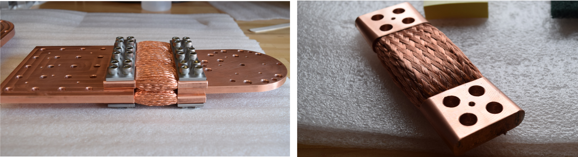
The heat straps connecting the pulse tube cooler to the 50K and 4K stages of the cryostat need to have large thermal conductance but also be fairly flexible to suppress vibrations transmitted to the focal plane. Bicep Array plans to use custom made oxygen-free high thermal conductivity (OFHC) copper assemblies each composed of multiple straps. As shown in Fig. 5 each heat strap consists of two end blocks connected by a series of multi-layered braided wire straps. The braided straps comprise seven layers of OFHC braid pressure fused into a small diameter OFHC pipe section on either end. The pressure fusing is performed by a hydraulic press under a load of 20 tons with lateral constraint provided by a steel die. We have been able to achieve thermal conductance of per strap at K in laboratory tests.
The heat straps in the Bicep Array cryostat combine a number of these straps to achieve high total thermal conductance. Two layers of braided straps are sandwiched around an OFHC plate on both ends. These plates provide mounting interfaces to the rest of the cryostat and the pulse tube cooler. Stainless steel plates on the top and bottom sides of this interface allow the use of 1/4” stainless steel bolts to create a high pressure joint and reduce thermal contact resistance. Figure 5 shows a fully assembled heat strap assembly that interfaces between the 4K radiation shield and the second stage of the pulse tube.
5 Mount and Operations
The larger size of the Bicep Array as compared to the Keck Array it replaces requires a larger motorized platform for operation. The new Bicep Array mount uses the same three-axis design as the previous Bicep/Keck experiments which augments the azimuth and elevation axes with rotation about the boresight of the array. A cross section of the new mount assembly is shown below in Fig. 6. As with previous Bicep/Keck experiments, the cryostats are enclosed within an accordion-like environmental shield which co-rotates in azimuth and flexes as the mount tips in elevation. A separate forward plate provides a mounting interface for four absorbative optical baffles—one per receiver—and co-rotates with the receivers about the array boresight.
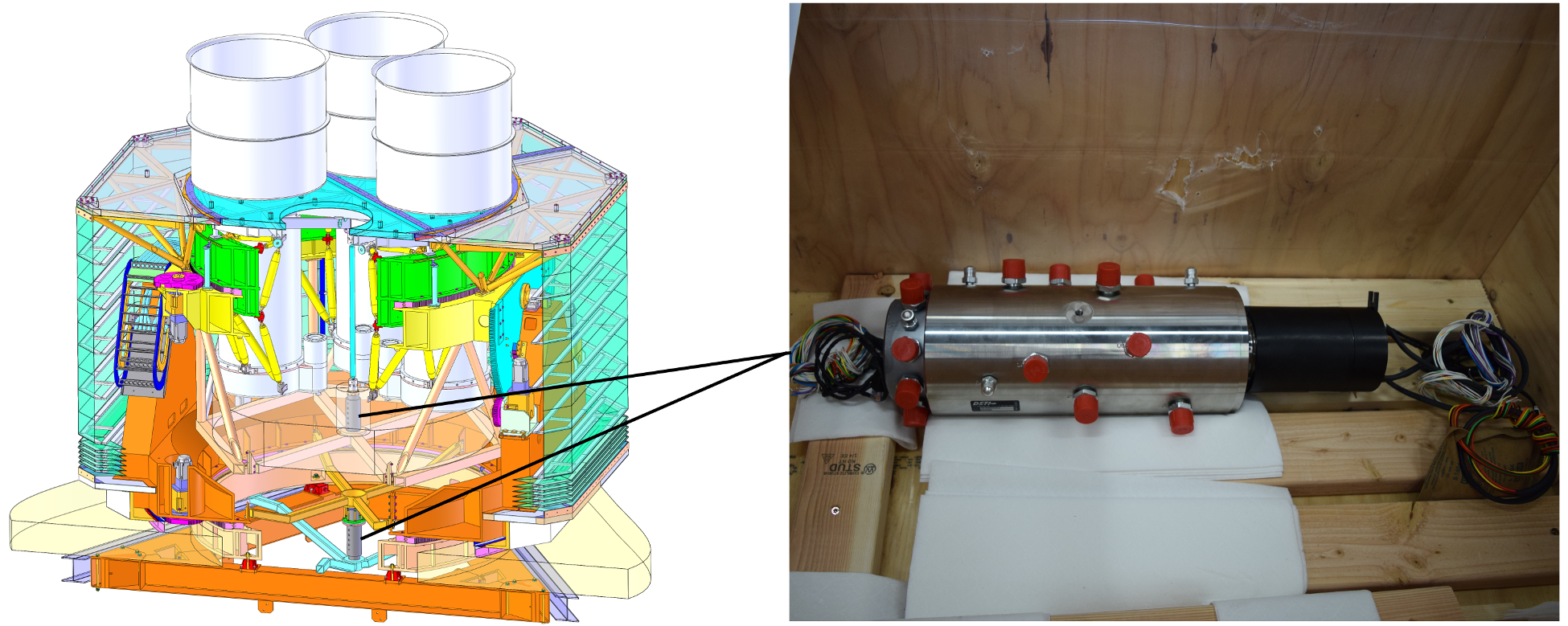
The Bicep Array mount includes two separate rotary unions which allow continuous rotation about the azimuth axis and array boresight without the need for a cable wrap (see Fig. 6). These rotary unions were designed at DSTI[15], and each contain 10 helium channels. Eight of these connect the pulse tubes and their compressors, while two channels serve as pressure guards. An additional nitrogen channel provides a pressurized environment on front end of the cryostats which prevents water absorption into the window material. The lip rings at the ends of the unions additionally provide data and power connections to electronics across separately rotating stages of the mount. These rotary unions allow the helium compressors—required to operate the pulse tube coolers—to sit well below the mount structure in the stationary tower. Helium lines route upwards into the lower (ground fixed) half of the first rotary union and then out through the upper half which rotates in azimuth along with the receivers. The hoses from the upper half are then routed through a short cable chain that provides flexure when rotating in elevation. The second rotary union is then similarly connected between the elevation and boresight stages.
Bicep Array will consist of four receivers observing in 6 frequency bands. Two receivers will continue to observe in the 95 and 150 GHz bands where the Bicep/Keck maps are deepest and where combined foreground signal is at a minimum. These will be augmented by two dual-band receivers at 30/40 GHz and 220/270 GHz. The 30/40 GHz receiver will extend the observations into two new bands at which the synchrotron foreground is expected to dominate. The Keck Array is already observing in the 220 and 270 GHz bands. However with significantly increased throughput, and a detector count of over 8 times the entire Keck Array, the dual band 220/270 GHz Bicep Array receiver will rapidly eclipse current sensitivity. In only a few days of observation, this receiver will surpass the dust sensitivity of the Planck 353 GHz data in the Bicep/Keck field. With the increased sensitivity at 95 and 150 GHz, these two additional receivers will be required to push constraints on polarized emission from galactic synchrotron and dust further than the currently available data.
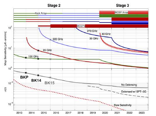
The observing power of Bicep Array will be concentrated on the same ( for Bicep3 generation) patch of sky as the existing Bicep/Keck data. By directly observing cosmological foregrounds with the new dual band receivers in the patch at which the Bicep/Keck data is already the deepest, we will be able to directly constrain these foregrounds in our own patch of sky, significantly reducing the effect of any spatial variation in the foregrounds’ spectral energy distribution. Increasing foreground constraints will be complemented by simultaneously increasing sensitivity to with the single band receivers. Figure 7 shows the sensitivity projections for Bicep Array. All projections are based on achieved sensitivity and as such, build in real world inefficiencies such as detector yield, weather, and other factors which decrease overall sensitivity. By the end of the program, Bicep Array is projected to constrain ( confidence), .
6 Acknowledgements
The Bicep/Keck projects have been made possible through a series of grants from the National Science Foundation including 0742818, 0742592, 1044978, 1110087, 1145172, 1145143, 1145248, 1639040, 1638957, 1638978, 1638970, & 1726917, by the Gordon and Betty Moore Foundation, and by the Keck Foundation. The development of antenna-coupled detector technology was supported by the JPL Research and Technology Development Fund and NASA Grants 06-ARPA206-0040, 10- SAT10-0017, 12-SAT12-0031, 14-SAT14-0009 & 16-SAT- 16-0002. The development and testing of focal planes were supported by the Gordon and Betty Moore Foundation at Caltech. Readout electronics were supported by a Canada Foundation for Innovation grant to UBC. The computations in this paper were run on the Odyssey cluster supported by the FAS Science Division Research Computing Group at Harvard University. The analysis effort at Stanford and SLAC is partially supported by the U.S. DoE Office of Science. We thank the staff of the U.S. Antarctic Program and in particular the South Pole Station without whose help this research would not have been possible. Most special thanks go to our heroic winter-overs Robert Schwarz and Steffen Richter. We thank all those who have contributed past efforts to the Bicep/Keck series of experiments, including the Bicep1 team.
References
- [1] Penzias, A. A. and Wilson, R. W., “A Measurement of Excess Antenna Temperature at 4080 Mc/s.,” Astrophys. J. 142, 419–421 (July 1965).
- [2] Dicke, R. H., Peebles, P. J. E., Roll, P. G., and Wilkinson, D. T., “Cosmic Black-Body Radiation.,” Astrophys. J. 142, 414–419 (July 1965).
- [3] Guth, A. H., “Inflationary universe: A possible solution to the horizon and flatness problems,” Phys. Rev. D 23, 347–356 (Jan. 1981).
- [4] Ogburn, IV, R. W., Ade, P. A. R., Aikin, R. W., Amiri, M., Benton, S. J., Bock, J. J., Bonetti, J. A., Brevik, J. A., Burger, B., Dowell, C. D., Duband, L., Filippini, J. P., Golwala, S. R., Halpern, M., Hasselfield, M., Hilton, G., Hristov, V. V., Irwin, K., Kaufman, J. P., Keating, B. G., Kovac, J. M., Kuo, C. L., Lange, A. E., Leitch, E. M., Netterfield, C. B., Nguyen, H. T., Orlando, A., Pryke, C. L., Reintsema, C., Richter, S., Ruhl, J. E., Runyan, M. C., Sheehy, C. D., Staniszewski, Z. K., Stokes, S. A., Sudiwala, R. V., Teply, G. P., Tolan, J. E., Turner, A. D., Wilson, P., and Wong, C. L., “The Bicep2 CMB polarization experiment,” in [Proceedings of SPIE ], 7741, 77411G (July 2010).
- [5] Sheehy, C. D., Ade, P. A. R., Aikin, R. W., Amiri, M., Benton, S., Bischoff, C., Bock, J. J., Bonetti, J. A., Brevik, J. A., Burger, B., Dowell, C. D., Duband, L., Filippini, J. P., Golwala, S. R., Halpern, M., Hasselfield, M., Hilton, G., Hristov, V. V., Irwin, K., Kaufman, J. P., Keating, B. G., Kovac, J. M., Kuo, C. L., Lange, A. E., Leitch, E. M., Lueker, M., Netterfield, C. B., Nguyen, H. T., Ogburn, IV, R. W., Orlando, A., Pryke, C. L., Reintsema, C., Richter, S., Ruhl, J. E., Runyan, M. C., Staniszewski, Z., Stokes, S., Sudiwala, R., Teply, G., Thompson, K. L., Tolan, J. E., Turner, A. D., Wilson, P., and Wong, C. L., “The Keck Array: a pulse tube cooled CMB polarimeter,” in [Proceedings of SPIE ], 7741 (July 2010).
- [6] The Bicep2 and Keck Array Collaborations, “Bicep/Keck VI: Improved Constraints on Cosmology and Foregrounds from Bicep2 and Keck Array Cosmic Microwave Background Data with Inclusion of 95 GHz Band,” Phys. Rev. Lett. 116, 031302 (Jan. 2016).
- [7] Ahmed, Z., Amiri, M., Benton, S. J., Bock, J. J., Bowens-Rubin, R., Buder, I., Bullock, E., Connors, J., Filippini, J. P., Grayson, J. A., Halpern, M., Hilton, G. C., Hristov, V. V., Hui, H., Irwin, K. D., Kang, J., Karkare, K. S., Karpel, E., Kovac, J. M., Kuo, C. L., Netterfield, C. B., Nguyen, H. T., O’Brient, R., Ogburn, R. W., Pryke, C., Reintsema, C. D., Richter, S., Thompson, K. L., Turner, A. D., Vieregg, A. G., Wu, W. L. K., and Yoon, K. W., “Bicep3: a 95GHz refracting telescope for degree-scale CMB polarization,” in [Proceedings of SPIE ], 9153 (Aug. 2014).
- [8] Hui, H., Ade, P. A. R., Ahmed, Z., Aikin, R. W., Alexander, K. D., Barkats, D., Benton, S. J., Bischoff, C. A., Bock, J. J., Bowens-Rubin, R., Brevik, J. A., Buder, I., Bullock, E., Buza, V., Connors, J., Cornelison, J., Crill, B. P., Crumrine, M., Dierickx, M., Duband, L., Dvirkin, C., Fillipini, J. P., Fliescher, S., Grayson, J., Hall, G., Halpern, M., Harrison, S., Hildebrandt, S. R., Hilton, G. C., Irwin, K. D., Kang, J., Karkare, K. S., Karpel, E., P., K. J., G., K. B., N., K. S., Kernasovskiy, S. A., M., K. J., Kuo, C. L., K., L., A., L. N., M., L. E., Lueker, M., Megerian, K. G., Moncelsi, L., Namikawa, T., Netterfield, C. B., Nguyen, H. T., O’Brient, R., Ogburn IV, R. W., Palladino, S., Pryke, C., Racine, B., Richter, S., Schwarz, R., Schillaci, A., Sheehy, C. D., Soliman, A., St. Germaine, T., Staniszewski, Z. K., Steinbach, B., Sudiwala, R. V., Teply, G. P., Thompson, K. L., Tolan, J. E., Tucker, C., Turner, A. D., Umiltà, C., Vieregg, A. G., Wandui, A., Weber, A. C., Wiebe, D. V., Willmert, J., Wong, C. L., Wu, W. L. K., Yang, E., Yoon, K. W., and Zhang, C., “BICEP Array: a Stage 3 CMB polarization experiment,” These Proceedings (2018).
- [9] Soliman, A., Ade, P. A. R., Ahmed, Z., Aikin, R. W., Alexander, K. D., Barkats, D., Benton, S. J., Bischoff, C. A., Bock, J. J., Bowens-Rubin, R., Brevik, J. A., Buder, I., Bullock, E., Buza, V., Connors, J., Cornelison, J., Crill, B. P., Crumrine, M., Dierickx, M., Duband, L., Dvirkin, C., Fillipini, J. P., Fliescher, S., Grayson, J., Hall, G., Halpern, M., Harrison, S., Hildebrandt, S. R., Hilton, G. C., Hui, H., Irwin, K. D., Kang, J., Karkare, K. S., Karpel, E., P., K. J., G., K. B., N., K. S., Kernasovskiy, S. A., M., K. J., Kuo, C. L., K., L., A., L. N., M., L. E., Lueker, M., Megerian, K. G., Moncelsi, L., Namikawa, T., Netterfield, C. B., Nguyen, H. T., O’Brient, R., Ogburn IV, R. W., Palladino, S., Pryke, C., Racine, B., Richter, S., Schwarz, R., Schillaci, A., Sheehy, C. D., St. Germaine, T., Staniszewski, Z. K., Steinbach, B., Sudiwala, R. V., Teply, G. P., Thompson, K. L., Tolan, J. E., Tucker, C., Turner, A. D., Umiltà, C., Vieregg, A. G., Wandui, A., Weber, A. C., Wiebe, D. V., Willmert, J., Wong, C. L., Wu, W. L. K., Yang, E., Yoon, K. W., and Zhang, C., “2017 upgrade and performance of Bicep3: a 95GHz refracting telescope for degree-scale CMB polarization,” These Proceedings (2018).
- [10] Kang, K., Ade, P. A. R., Ahmed, Z., Aikin, R. W., Alexander, K. D., Barkats, D., Benton, S. J., Bischoff, C. A., Bock, J. J., Bowens-Rubin, R., Brevik, J. A., Buder, I., Bullock, E., Buza, V., Connors, J., Cornelison, J., Crill, B. P., Crumrine, M., Dierickx, M., Duband, L., Dvirkin, C., Fillipini, J. P., Fliescher, S., Grayson, J., Hall, G., Halpern, M., Harrison, S., Hildebrandt, S. R., Hilton, G. C., Hui, H., Irwin, K. D., Karkare, K. S., Karpel, E., P., K. J., G., K. B., N., K. S., Kernasovskiy, S. A., M., K. J., Kuo, C. L., K., L., A., L. N., M., L. E., Lueker, M., Megerian, K. G., Moncelsi, L., Namikawa, T., Netterfield, C. B., Nguyen, H. T., O’Brient, R., Ogburn IV, R. W., Palladino, S., Pryke, C., Racine, B., Richter, S., Schwarz, R., Schillaci, A., Sheehy, C. D., Soliman, A., St. Germaine, T., Staniszewski, Z. K., Steinbach, B., Sudiwala, R. V., Teply, G. P., Thompson, K. L., Tolan, J. E., Tucker, C., Turner, A. D., Umiltà, C., Vieregg, A. G., Wandui, A., Weber, A. C., Wiebe, D. V., Willmert, J., Wong, C. L., Wu, W. L. K., Yang, E., Yoon, K. W., and Zhang, C., “2017 upgrade and performance of Bicep3: a 95GHz refracting telescope for degree-scale CMB polarization,” These Proceedings (2018).
- [11] Amuneal Manufacturing Corp. http://www.amuneal.com.
- [12] Cryomech, Inc. http://www.cryomech.com/.
- [13] “National institute of standards and technology: Materials measurement laboratory - cryogenic technologies group.” http://cryogenics.nist.gov.
- [14] Runyan, M. C. and Jones, W. C., “Thermal conductivity of thermally-isolating polymeric and composite structural support materials between 0.3 and 4 K,” Cryogenics 48, 448–454 (Sept. 2008).
- [15] “Dynamic sealing technologies, inc..” https://www.dsti.com.
- [16] The Bicep/Keck and Planck Collaborations, “Joint Analysis of Bicep/Keck and Planck Data,” Phys. Rev. Lett. 114, 101301 (Mar. 2015).