Further author information send correspondence to H. Hui
H. Hui: E-mail: hhui@caltech.edu, Telephone: 1 626 395 2023
BICEP Array: a multi-frequency degree-scale CMB polarimeter
Abstract
Bicep Array is the newest multi-frequency instrument in the Bicep/Keck Array program. It is comprised of four 550 mm aperture refractive telescopes observing the polarization of the cosmic microwave background (CMB) at 30/40, 95, 150 and 220/270 GHz with over 30,000 detectors. We present an overview of the receiver, detailing the optics, thermal, mechanical, and magnetic shielding design. Bicep Array follows Bicep3 ’s modular focal plane concept, and upgrades to 6” wafer to reduce fabrication with higher detector count per module. The first receiver at 30/40 GHz is expected to start observing at the South Pole during the 2019-20 season. By the end of the planned Bicep Array program, we project , assuming current modeling of polarized Galactic foreground and depending on the level of delensing that can be achieved with higher resolution maps from the South Pole Telescope.
keywords:
Cosmic Microwave Background, Polarization, Instrumentation1 Introduction
Measurements of the polarization of the Cosmic Microwave Background provide key information to further our understanding of the early universe. The CDM model predicts an -mode polarization pattern in the CMB at the level of a few K as well as an arc-minute -mode polarization arising from gravitational lensing of -modes by the large-scale structure of the universe. Inflationary gravitational waves may be a source of degree-scale -mode polarization and a detection of such signal can be used to constrain the tensor-scalar ratio and place limits on the energy scale and potential of Inflation [1]. While classes of Inflation models could generate undetectably low levels of gravitational waves, a detection of -mode polarization generated by primordial gravitational waves would be direct evidence for the theory of Inflation. However, in order to disentangle a potential CMB signal from polarized Galactic dust and synchrotron foregrounds, we need to probe the polarization of the CMB at multiple frequencies with high sensitivity.
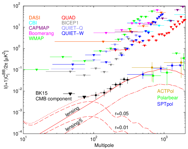
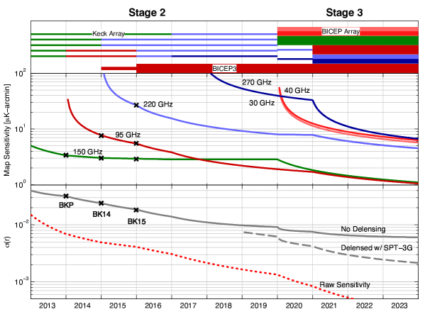
The current constraint on tensor-to-scalar ratio is at 95% confidence from Bicep/Keck Array data in conjunction with Planck temperature measurements [2] (Figure 1). Over the past 10 years, our experimental strategy of utilizing small-aperture, cold, refracting telescopes has proven to be successful to probe the degree-scale polarization of the CMB. Bicep2 observed the sky with 500 antenna-coupled transition-edge sensor (TES) bolometers at 150 GHz from 2010 to 2012, and reported a 5 excess of -mode power over the base lensed-CDM model in the range [3]. The Keck Array consists of five 25 cm aperture receivers, each similar to Bicep2, started observations at 150 GHz in 2012. A joint analysis with Planck indicated the signal reported from Bicep2 is consistent with polarized emission from Galactic dust [4]. The interchangeable Keck Array receivers allowed us to diversify the frequency coverage by rapidly switching each receiver to 95, 220, and 270 GHz. The latest instrument in our program, Bicep3, replaced Bicep2 on its mount in 2015. Bicep3 uses a 0.52 m telescope and 2500 detectors operating at 95 GHz to realize an on-sky instantaneous sensitivity of 6.7 [5]. Figure 2 shows the progression of the Bicep/Keck Array program, to larger apertures, larger focal planes, and wider frequency coverage.
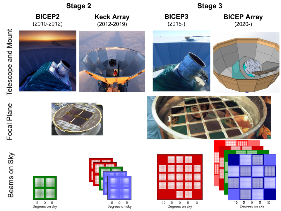
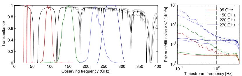
Bicep Array adopts the same interchangeable concept used in Keck Array and is comprised of four Bicep3-class receivers, each optimized for a atmospheric window in the frequency range from 30 to 270 GHz (Figure 3). The highest and lowest frequency receivers incorporate two bands within an atmospheric window, operating at 30/40 GHz and 220/270 GHz, by shifting bandpass in alternating focal plane modules over the focal plane (Figure 2). The splitting of the band provides more information on polarized Galactic synchrotron and dust emission to test the parameters of the foreground model.
The Keck Array telescope mount will be replaced by the new Bicep Array mount[6] at the end of 2019. Bicep Array receivers will be installed in the new mount in a staged approach over the next few years, with the first 30/40 GHz receiver to be deployed at the end of 2019, followed by the 150, 95 and 220/270 GHz receivers. We are currently planning on continuing observations with a subset of the Keck Array receivers installed in open slots until they are filled by available Bicep Array receivers. The parameters of the Keck Array, Bicep3 and Bicep Array receivers are given in Table 1.
| Receiver | Nominal | Nominal Single | Beam | Survey Weight |
| Observing Band | Number of | Detector NET | FWHM | Per Year |
| (GHz) | Detectors | () | (arcmin) | ()-2 yr-1 |
| Keck Array | ||||
| 95 | 288 | 288 | 43 | 24,000 |
| 150 | 512 | 313 | 30 | 30,000 |
| 220 | 512 | 837 | 21 | 2,000 |
| 270 | 512 | 1310 | 17 | 800 |
| Bicep3 | ||||
| 95 | 2560 | 288 | 24 | 213,000 |
| Bicep Array | ||||
2 Bicep Array instrument overview
2.1 Receiver overview
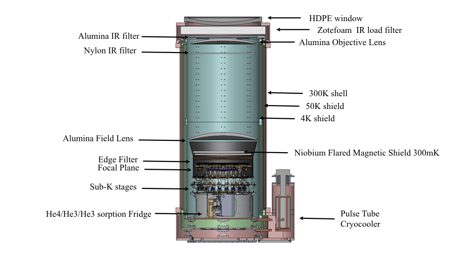
Bicep Array is largely based on the successful design of Bicep3[7]. Each receiver is housed in a custom-designed vacuum cryostat 2.1 m tall and 0.9 m in diameter (excluding the additional envelopes of the multi-channel readout electronics and the pulse-tube cooler). Figure 4 shows a cross-section of the receiver. The vacuum jacket and the 50 K stages are constructed with a short base stage, and long cylinders for the main section. This allows us to lift off the outer cylinders from the base plate without removing the cabling, thermal joints and focal plane structure. The top of the vacuum jacket is capped by a vacuum window (made out of HDPE for the 30/40 GHz receiver; solutions for the higher frequencies are discussed in a companion paper[8]), and a stack of Zotefoam® infrared filters behind it. An IR-absorptive alumina filter[9] is installed at the top of the 50 K stage.
The 4 K stage is sectioned into two lengthwise segments for ease of access during integration; the top optics section houses the optical elements, including the two alumina lenses, and potentially a nylon filter, to absorb long-wavelength infrared emission before reaching the sub-K focal plane. The lower camera section houses the sub-kelvin cryogenic system, time-domain multiplexed SQUID readouts, and the sub-kelvin focal plane with a thermo-mechanical truss structure.
The 50 K volume is supported by G-10 trusses, providing robust structural support while maintaining low thermal conductivity between temperature stages. The 4 K and sub-Kelvin structures are supported by carbon fiber trusses because of its high ratio of stiffness to thermal conductivity at low temperature[10].
2.2 Thermal Architecture
The radiative loading from the window and warmer stages in Bicep Array dominates over conducted loading inside the receiver, thus the receiver’s thermal architecture is focused on minimizing the instrument internal loading on the detectors. The 50 K and 4 K stages are heat sunk to the first and second stages of a Cryomech111Cryomech, Inc. (www.cryomech.com) PT-415 cooler, with cooling capacity of 40 W and 1.5 W, respectively.
The 56 cm aperture window lets W of infrared radiation into the receiver. The current baseline material for the vacuum window is 1”-thick HDPE at 30/40 GHz, where HDPE has negligible in-band emission, but at higher frequencies thinner windows using polyethylene fiber composites will reduce the in-band optical loading and thereby significantly improve mapping speed[8]. Within the receiver, we use a combination of Zotefoam® filters, alumina optics and a nylon filter to reduce infrared loading to an acceptable level for the sub-Kelvin stages to function. Combining actual measurements from Bicep3 with a thermal model, the total loading on the 50 K and 4 K stages is estimated to be about 21 W and 0.38 W, respectively, implying actual base temperatures of 34 K and 3.1 K at these stages.
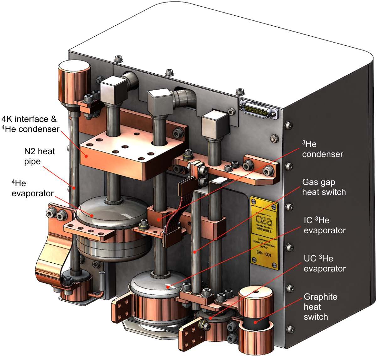
Sub-Kelvin cooling for the detectors is provided by a three-stage helium (4He/3He/3He) sorption fridge from CEA Grenoble[11] (Figure 5) at 2 K (4He stage), 340 mK (intermediate cold), and 250 mK (ultra-cold). With estimating 20 and 15 W of optical loading at 340 and 230 mK stages, it has sufficient cooling capacity to have a 3-day uninterrupted observing schedule between thermal cycles. The detector modules and focal plane are heat sunk to the ultra-cold stage via a flexible high-purity copper-foil heat strap. The strap connects to the focal plane through a stainless steel block. The temperature of the strap is actively regulated, and the block serves as a passive low-pass thermal filter to attenuate thermal noise from the control circuit. The estimated conductive loading on the ultra-cold stage is 0.25 W (not including radiative contributions, see Table 2).
| Conducted load budget for the focal plane assembly | |||
|---|---|---|---|
| 2 K (W) | 340 mK (W) | 230 mK (nW) | |
| 16 NbTi cables | 110.7 | 27.7 | 99.6 |
| 4 Manganin cables | 3.2 | 0.9 | 3.5 |
| Cernox cables | 11.0 | 2.1 | 3.0 |
| Heater cables | 4.6 | 0.8 | 2.3 |
| Carbon fiber trusses | 44.0 | 16.9 | 47.1 |
| Aluminize mylar shield | 52.9 | 23.4 | 97.8 |
| Total | 226.5 | 71.7 | 253.2 |
2.3 Housekeeping electronics
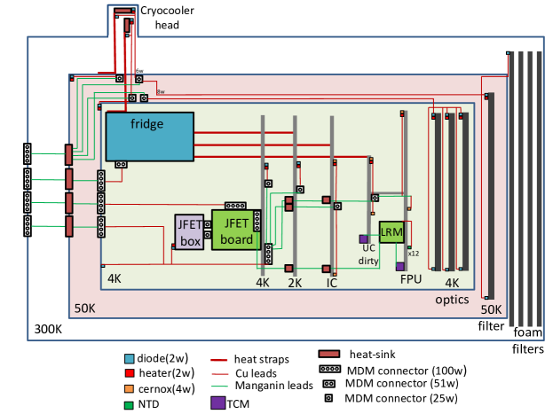
Thermal monitoring for the cryostat is done using calibrated diodes and resistance thermometers (cernox®) at the radiation shields, critical cryogenic junctions, and some of the optical elements. The focal plane temperature is regulated by passive and active filtering as described above, similar to the approach used on Keck Array and Bicep3. Active control is implemented in a feedback loop using Neutron transmutation doped (NTD) Ge thermometers and a resistive heater. The design uses the same precision NTD Ge thermometry to passively monitor focal plane temperatures. Figure 6 shows the cold housekeeping layout in Bicep Array.
Warm housekeeping electronics consist of an analog electronics enclosure, which interfaces to the cryostat and is responsible for biasing thermometers and pre-amplifying their signals, and a commercial electronics crate222United Electronic Industries (www.ueidaq.com), which digitizes thermometry signals and sets heater voltages. The housekeeping electronics support up 64 thermometry channels and 32 heater channels for each Bicep Array receiver.
2.4 Optics
Following the same concept as in previous telescopes, Bicep Array uses a simple diffraction-limited refractor, which provides a telecentric and flat focal surface with minimum aberrations over a wide field of view. The telescope has a mean -ratio of /1.6, and the alumina lenses are 650 mm in diameter, with a clear aperture of 550 mm and a field of view of 29.6 degree. Figure 7 shows the optical diagram of the 30/40 GHz design. The lenses in Bicep Array are cooled to 4 K to minimize loading on the detectors. The 4 K space between the objective and the field lens is covered in epoxy-encapsulated Eccosorb® HR-10 microwave absorber to suppress far-sidelobes reflections. The same Eccosorb® is also used to define the 550 mm optical stop for the system, located behind the objective lens (in the anti-sky direction). Simulations show the Gaussian beam width is at 30/40 GHz. Given the similarity to the Bicep3 design, we expect the actual values to compare well to the design model.
2.5 Focal plane and detector module
The sub-Kelvin structure is located on top of the 4 K base plate, above the sorption fridge. It is separated into three thermal, “wedding-cake” stages at 2 K, 350 mK, and 260 mK. Each stage provides radiative shielding and room for cable heat-sinking to the respective fridge stages, allowing low loading environment for the focal plane and detectors. The copper focal-plane plate is mounted at the 250 mK stage, separated by a low-pass stainless steel filter and carbon fiber trusses.
Extensive finite-element simulations were performed on the truss structure to estimate its maximum static load as well as its vibrational resonances. The minimum resonance frequency for the carbon fiber truss structure is 55 Hz. The maximum displacement of the truss structure when subject to a 90 degree gravity load is less than 70 m at the focal plane. The first buckling mode of the structure, with a 45 degrees gravity load, is found to be more than 9 times the nominal load in correspondence of the carbon fibers truss elements. In practice the glued joints are usually weaker than in simulation, so all truss elements will go through warm and cold stress tests before installation.
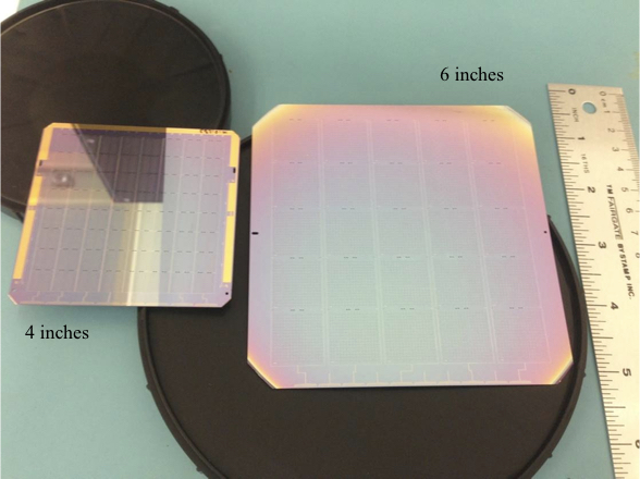
Twelve detector modules are tiled onto the focal plane, each containing 32 to 2178 antenna-coupled transition-edge sensors[13], depending on the observing frequency (Table 1). The module is based on the successful Bicep3 design[14], except the detectors are now fabricated on 6” silicon wafers, instead of the previous 4” wafers to expedite lithographic fabrication with higher detector count per module (Figure 8). The total number of module is also reduced in the focal plane, simplifies the assembly procedure and reduces the non-optically illuminated metal frame area between modules. The first-stage SQUID readout multiplexing chips are housed in a silicon/aluminum-nitride circuit board inside the module. The housing is constructed with superconducting niobium and aluminum. Combining with the high- A4K sheet inside the module, it is designed to achieve high magnetic shielding performance (Section 2.7). Figure 9 shows the exploded view of the module design.
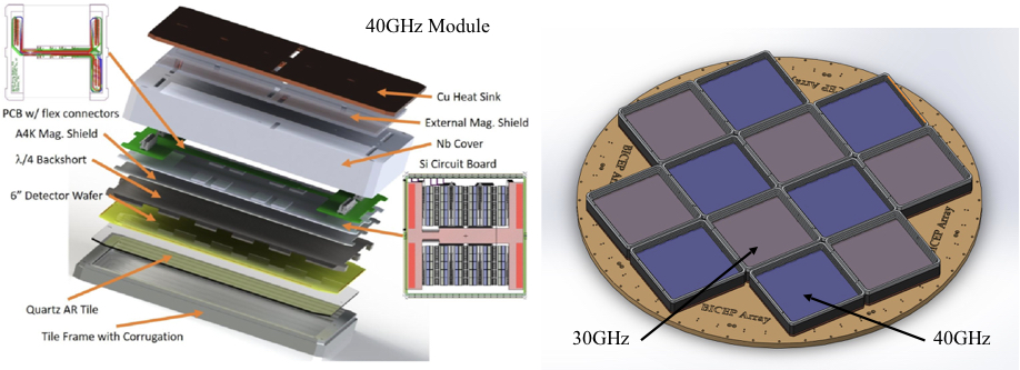
Interaction between the edge antennas and the metal frame around the module cause differential ellipticity, resulting in potential temperature to polarization leakage in the CMB maps. We designed corrugated walls to minimize this effect. The 30/40 GHz module implements a novel double-corrugation wall that mitigates the differential ellipticity caused by the metal frame over 57% bandwidth, from 25 GHz to 45 GHz [15].
2.6 Detector Readout
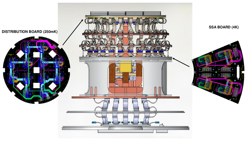
Bicep Array uses a time-domain multiplexing (TDM) readout system identical to Bicep3 for the 30/40, 95, and 150 GHz receivers [14]. Table 3 shows the multiplexing factors and arrangement for each receiver. The first stage SQUIDs are integrated into the detector module. A circuit board (distribution board) is mounted underneath the copper focal plane, gathering all the readout cabling and distributing to the corresponding detector module. The housekeeping electronics and series SQUID array (SSA) amplification stage are placed on the 4 K base plate circuit boards (Figure 10). The amplified detector signals are digitized and read out using the warm Multi-Channel Electronics (MCE[16]), which also provide SQUIDs and detector bias, and apply feedback for control. The large number of MCEs needed at 150 GHz required a relatively minor mechanical redesign of the MCE boxes in order to fit within the space constraints imposed by the telescope mount.
The 220/270 GHz receiver, with more than 22,000 detector channels, will require a new readout technology. Thermal kinetic inductance detectors [17] (TKID), and microwave SQUID multiplexing [18] (MUX) technologies provide the higher multiplexing factors to handle such large formats and are being developed for the high frequency receiver within the collaboration.
| Frequency | 30/40 GHz | 95 GHz | 150 GHz |
|---|---|---|---|
| # Detector Tiles | 12 | 12 | 12 |
| # Detectors | 192 + 300 | 3456 | 7776 |
| # Detectors/Tile | 32 + 50 | 288 | 648 |
| # SQUID MUX11 chips/Tile | 6 | 28 | 64 |
| # MCE | 1 | 3 | 6 |
| # Columns/MCE | 24 | 28 | 32 |
| # Rows (multiplexing factor) | 33 | 43 | 42 |
2.7 Magnetic shielding
The SQUID readout system is susceptible to external magnetic fields and Bicep Array’s magnetic shielding architecture is designed to minimize the level of spurious signals generated as the telescope moves along the Earth’s magnetic field lines. The shielding configuration is optimized using COMSOL Multiphysics333COMSOL, Inc., Burlington, MA 01803 (www.comsol.com), which allowed us to simulate the Meissner behavior of a superconducting material.
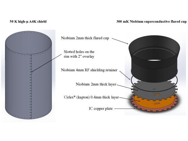
The first stage of shielding is achieved by the combination of a 1 mm thick high- A4K sheet wrapped around the 50 K stage, and a 2 mm thick superconducting niobium flared cup on the 350 mK stage (Figure 11). Slotted mounting holes on the 50 K shield allow sufficient thermal expansion mismatch between the aluminum and A4K. The sub-Kelvin niobium shield required a continuous base in addition to the flared cylinder to enhance the shielding performance. The niobium base is not electrically connected to the copper base plate to avoid potential superconductor-metal interactions at the contact surface. The receiver-level shielding provides a suppression factor from external magnetic fields.
The detectors and first stage SQUIDs are further protected by the module housing. The combination of the aluminum detector frame, with a niobium backshort and niobium enclosed-box form a semi-enclosed, superconducting environment for the readout electronics. Simulation shows the biggest field leakage comes from the slots for the readout cables. An additional niobium sheet, offsetting the cable slots is mounted on the backside of the module niobium housing to minimize the leakage. To further increase the shielding, a 0.020” thick high- A4K sheet is placed in between the niobium backshort and the circuit boards, 1 mm away from the SQUID chips to draw the remaining, unwanted magnetic field away from the SQUIDs. We estimate a final shielding factor in excess of 500 from the detector module. Table 4 shows the simulated magnetic shielding performance of the receiver and module.
| Parts | Axial Residual Flux | Transverse Residual Flux |
|---|---|---|
| 50K and 4K shield | 0.24% | 0.52% |
| Detector module | 0.12% | 0.20% |
| Final shielding | 0.0003% | 0.001% |
3 Observation strategy and projected performance
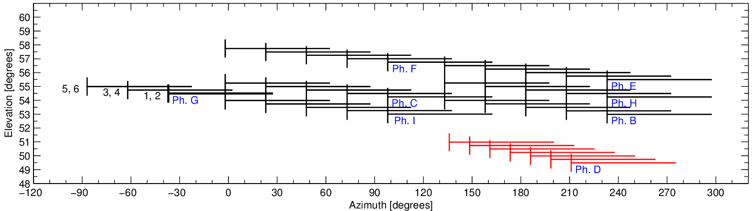
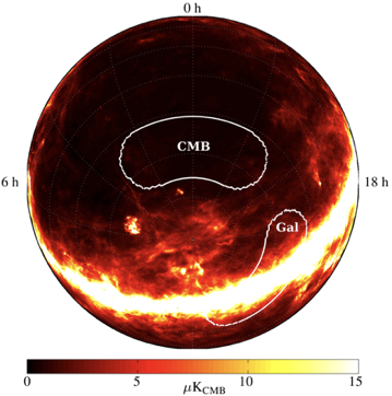
Bicep Array focuses its CMB observations on the same sky patch as Bicep3, spanning right ascension RA and declination , with an effective area of (larger than Keck Array’s but colocated). With the full Bicep Array sensitivity, we expect to achieve and surpass the Planck map depths at all frequencies after only a few months of observations. Figure 12 shows the planned observing strategy, which is identical to the current Bicep3 schedule.
The parameters of the Keck Array, Bicep3, and Bicep Array are given in Table 1. The Bicep Array sensitivity estimate is based on achieved survey weight per year of the Keck Array. This procedure accounts for all real-world observing imperfections such as detector yield, cryogenic efficiency, data cuts, ground subtraction, temporal filtering, and other unexpected events that decrease the final sensitivity compared to the ideal case. Figure 13 shows the projected sensitivity of the ongoing and planned Bicep program. We expected to reach at the end of the program, depending on the level of delensing that can be achieved using higher-resolution data from the South Pole Telescope.
Acknowledgements.
The Bicep/Keck Array project have been made possible through a series of grants from the National Science Foundation including 0742818, 0742592, 1044978, 1110087, 1145172, 1145143, 1145248, 1639040, 1638957, 1638978, 1638970, & 1726917 and by the Keck Foundation. The development of antenna-coupled detector technology was supported by the JPL Research and Technology Development Fund and NASA Grants 06-ARPA206-0040, 10-SAT10-0017, 12-SAT12-0031, 14-SAT14-0009 & 16-SAT16-0002. The development and testing of focal planes were supported by the Gordon and Betty Moore Foundation at Caltech. Readout electronics were supported by a Canada Foundation for Innovation grant to UBC. The computations in this paper were run on the Odyssey cluster supported by the FAS Science Division Research Computing Group at Harvard University. The analysis effort at Stanford and SLAC is partially supported by the U.S. DoE Office of Science. We thank the staff of the U.S. Antarctic Program and in particular the South Pole Station without whose help this research would not have been possible. Tireless administrative support was provided by Kathy Deniston, Sheri Stoll, Irene Coyle, Donna Hernandez, and Dana Volponi.References
- [1] Kamionkowski, M. and Kovetz, E. D., “The quest for b modes from inflationary gravitational waves,” Annual Review of Astronomy and Astrophysics 54, 227–269 (2016).
- [2] BICEP2 Collaboration and Keck Array Collaboration, “BICEP2 / Keck Array X: Improved Constraints on Inflationary Gravitational Waves using BICEP2/Keck Data up to the 2015 Season in Conjunction with WMAP/Planck,” ArXiv 18xx.xxxxx (2018).
- [3] Ade, P. A., Aikin, R. W., Barkats, D., Benton, S. J., Bischoff, C. A., Bock, J. J., Brevik, J. A., Buder, I., Bullock, E., Dowell, C. D., et al., “Detection of b-mode polarization at degree angular scales by bicep2,” Physical Review Letters 112(24), 241101 (2014).
- [4] BICEP2/Keck Collaboration, Planck Collaboration, Ade, P. A. R., Aghanim, N., Ahmed, Z., Aikin, R. W., Alexander, K. D., Arnaud, M., Aumont, J., Baccigalupi, C., and et al., “Joint Analysis of BICEP2/Keck Array and Planck Data,” Physical Review Letters 114, 101301 (Mar. 2015).
- [5] Kang, J., Ade, P., Ahmed, Z., Alexander, K. D., Amiri, M., Barkats, D., Benton, S., Bischoff, C. A., Bock, J., Boenish, H., et al., “2017 upgrade and performance of bicep3: a 95ghz refracting telescope for degree-scale cmb polarization,” in [Millimeter, Submillimeter, and Far-Infrared Detectors and Instrumentation for Astronomy VIII ], International Society for Optics and Photonics (2018).
- [6] Crumrine, M., Ade, P., Ahmed, Z., Alexander, K. D., Amiri, M., Barkats, D., Benton, S., Bischoff, C. A., Bock, J., Boenish, H., et al., “Bicep array cryostat and mount design,” in [Millimeter, Submillimeter, and Far-Infrared Detectors and Instrumentation for Astronomy VIII ], International Society for Optics and Photonics (2018).
- [7] Wu, W. L. K., Ade, P. A. R., Ahmed, Z., Alexander, K. D., Amiri, M., Barkats, D., Benton, S. J., Bischoff, C. A., Bock, J. J., Bowens-Rubin, R., Buder, I., Bullock, E., Buza, V., Connors, J. A., Filippini, J. P., Fliescher, S., Grayson, J. A., Halpern, M., Harrison, S. A., Hilton, G. C., Hristov, V. V., Hui, H., Irwin, K. D., Kang, J., Karkare, K. S., Karpel, E., Kefeli, S., Kernasovskiy, S. A., Kovac, J. M., Kuo, C. L., Megerian, K. G., Netterfield, C. B., Nguyen, H. T., O’Brient, R., Ogburn, R. W., Pryke, C., Reintsema, C. D., Richter, S., Sorensen, C., Staniszewski, Z. K., Steinbach, B., Sudiwala, R. V., Teply, G. P., Thompson, K. L., Tolan, J. E., Tucker, C. E., Turner, A. D., Vieregg, A. G., Weber, A. C., Wiebe, D. V., Willmert, J., and Yoon, K. W., “Initial Performance of Bicep3: A Degree Angular Scale 95 GHz Band Polarimeter,” Journal of Low Temperature Physics 184, 765–771 (Aug. 2016).
- [8] Dierickx, M., Ade, P., Ahmed, Z., Alexander, K. D., Amiri, M., Barkats, D., Benton, S., Bischoff, C. A., Bock, J., Boenish, H., et al., “Design and optimization of vacuum windows for the bicep/keck array cmb experiment,” in [Millimeter, Submillimeter, and Far-Infrared Detectors and Instrumentation for Astronomy VIII ], International Society for Optics and Photonics (2018).
- [9] Inoue, Y., Matsumura, T., Hazumi, M., Lee, A. T., Okamura, T., Suzuki, A., Tomaru, T., and Yamaguchi, H., “Cryogenic infrared filter made of alumina for use at millimeter wavelength,” Applied optics 53(9), 1727–1733 (2014).
- [10] Runyan, M. C. and Jones, W. C., “Thermal conductivity of thermally-isolating polymeric and composite structural support materials between 0.3 and 4 K,” Cryogenics 48, 448–454 (Sept. 2008).
- [11] Duband, L., Prouve, T., Bock, J. J., Moncelsi, L., and Schillaci, A., “Sub-kelvin cooling for the bicep array project,” in [Cryocoolers 20 ], International Cryocooler Conference, Inc., Burlington, VT (2018).
- [12] Hui, H., Measuring the Polarization of the Cosmic Microwave Background with BICEP3, PhD thesis, California Institute of Technology (2018).
- [13] BICEP2 Collaboration, Keck Array Collaboration, SPIDER Collaboration, Ade, P. A. R., Aikin, R. W., Amiri, M., Barkats, D., Benton, S. J., Bischoff, C. A., Bock, J. J., Bonetti, J. A., Brevik, J. A., Buder, I., Bullock, E., Chattopadhyay, G., Davis, G., Day, P. K., Dowell, C. D., Duband, L., Filippini, J. P., Fliescher, S., Golwala, S. R., Halpern, M., Hasselfield, M., Hildebrandt, S. R., Hilton, G. C., Hristov, V., Hui, H., Irwin, K. D., Jones, W. C., Karkare, K. S., Kaufman, J. P., Keating, B. G., Kefeli, S., Kernasovskiy, S. A., Kovac, J. M., Kuo, C. L., LeDuc, H. G., Leitch, E. M., Llombart, N., Lueker, M., Mason, P., Megerian, K., Moncelsi, L., Netterfield, C. B., Nguyen, H. T., O’Brient, R., Ogburn, IV, R. W., Orlando, A., Pryke, C., Rahlin, A. S., Reintsema, C. D., Richter, S., Runyan, M. C., Schwarz, R., Sheehy, C. D., Staniszewski, Z. K., Sudiwala, R. V., Teply, G. P., Tolan, J. E., Trangsrud, A., Tucker, R. S., Turner, A. D., Vieregg, A. G., Weber, A., Wiebe, D. V., Wilson, P., Wong, C. L., Yoon, K. W., and Zmuidzinas, J., “Antenna-coupled TES Bolometers Used in BICEP2, Keck Array, and Spider,” Astrophys. J. 812, 176 (Oct. 2015).
- [14] Hui, H., Ade, P., Ahmed, Z., Alexander, K. D., Amiri, M., Barkats, D., Benton, S., Bischoff, C. A., Bock, J., Boenish, H., et al., “Bicep3 focal plane design and detector performance,” in [Millimeter, Submillimeter, and Far-Infrared Detectors and Instrumentation for Astronomy VIII ], 9914, 99140T, International Society for Optics and Photonics (2016).
- [15] Soliman, A., Ade, P., et al., “Design and performance of single/wide band corrugated walls for the bicep array detector modules at 30/40 ghz,” in [Millimeter, Submillimeter, and Far-Infrared Detectors and Instrumentation for Astronomy VIII ], International Society for Optics and Photonics (2018).
- [16] Battistelli, E. S., Amiri, M., Burger, B., Halpern, M., Knotek, S., Ellis, M., Gao, X., Kelly, D., Macintosh, M., Irwin, K., and Reintsema, C., “Functional Description of Read-out Electronics for Time-Domain Multiplexed Bolometers for Millimeter and Sub-millimeter Astronomy,” Journal of Low Temperature Physics 151, 908–914 (May 2008).
- [17] O’Brient, R. et al., “Thermal kinetic inductance detectors for cmb and sub millimeter observations,” in [Millimeter, Submillimeter, and Far-Infrared Detectors and Instrumentation for Astronomy VIII ], International Society for Optics and Photonics (2018).
- [18] Henderson, S. et al., “Highly-multiplexed microwave squid readout using the slac microresonator radio frequency (smurf) electronics for future cmb and sub-millimeter surveys,” in [Millimeter, Submillimeter, and Far-Infrared Detectors and Instrumentation for Astronomy VIII ], International Society for Optics and Photonics (2018).