Suzhi Bi, Xiaohui Lin
Shenzhen, Guangdong, 518060, China
11email: zhengyuan2016@email.szu.edu.cn,bsz,xhlin@szu.edu.cn
Backscatter-assisted Relaying in Wireless Powered Communications Network
Abstract
This paper studies a novel cooperation method in a two-user wireless powered communication network (WPCN), in which one hybrid access point (HAP) broadcasts wireless energy to two distributed wireless devices (WDs), while the WDs use the harvested energy to transmit their independent information to the HAP. To tackle the user unfairness problem caused by the near-far effect in WPCN, we allow the WD with the stronger WD-to-HAP channel to use part of its harvested energy to help relay the other weaker user’s information to the HAP. In particular, we exploit the use of backscatter communication during the wireless energy transfer phase such that the helping relay user can harvest energy and receive the information from the weaker user simultaneously. We derive the maximum common throughput performance by jointly optimizing the time duration and power allocations on wireless energy and information transmissions. Our simulation results demonstrate that the backscatter-assisted cooperation scheme can effectively improve the throughput fairness performance in WPCNs.
1 Introduction
Wireless communication is fundamentally constrained by the limited battery life of wireless devices. Frequent battery replacement/recharging will interrupt wireless communication and degrade the quality of communication service. Alternatively, radio frequency (RF) enabled wireless energy transfer (WET) technology can supply continuous and sustainable energy to remote WDs. Its application in wireless communication introduces a new networking paradigm, named wireless powered communication network (WPCN). Recent studies have shown that its deployment can largely reduce the network operational cost, and effectively improve the communication performance, e.g., achieving longer operating time and more stable throughput 2014:Bi ; 2016:Bi1 ; 2014:Ju1 ; 2016:Bi2 ; 2017:Bi ; 2018:Bi ; 2015:Bi . For example, 2014:Ju1 proposed a harvest-then-transmit protocol in WPCN, where one hybrid access point (HAP) with single antenna first transfer RF energy to all WDs in the downlink (DL), and then the WDs transmit information to the HAP in the uplink (UL) using their received energy in a time-division-multiple-access (TDMA) manner. It is observed in 2014:Ju1 that the WPCN suffers from a doubly near-far problem among WDs in different locations, where a far user from the HAP achieves low throughput because they receive less energy and need more power to transmit information. To solve the doubly near-far problem and improve user fairness, several different user cooperation schemes have been proposed 2014:Ju2 ; 2017:MM ; 2017:Yuan ; 2017:Wu . For instance, 2014:Ju2 proposed a two-user cooperation, where the near user helps relay the far user’s information to the HAP. 2017:MM allows two cooperating users to from a distributed virtual antenna array. 2017:Yuan considered a cluster-based user cooperation, where a multi-antenna HAP applies WET to power a cluster of remote WDs and receives their data transmissions.
A major design issue of the existing user cooperation schemes is that the overhead (both energy and time) consumed on information exchange between the collaborating users. Alternatively, the recent development of ambient backscatter (AB) communication provides an alternative to reduce such collaborating overhead. Specifically, AB enables a WD to transmit information passively to another device in the vicinity by backscattering the RF signal in the environment, e.g., WiFi and cellular signals, thus achieving device battery conservation. Several recent studies have devoted to improve the data rate of AB, such as proposing new signal detection method and AB communication circuit designs 2013:Vli ; 2016:Gw . However, the performance of conventional ambient backscatter communication greatly depends on the conditions of time-varying ambient RF signal, which is not controllable in either its strength or time availability.
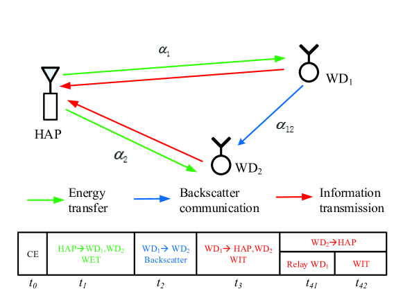
In this paper, we consider a novel user cooperation method in WPCN which uses backscatter communication. As shown in Fig. 1, we consider two wirelessly powered WDs that harvest RF energy in the DL and transmit cooperatively their information to the HAP in the UL. Unlike in conventional cooperation in WPCN where one WD transmits its information actively to the helping WD, we reuse the WET signal for achieving simultaneous information transmission in a passive manner. This largely saves the collaborating overhead. Besides, compared to conventional AB communication, the use of WET is fully controllable in the RF signal strength and transmission time. With the proposed backscatter-assisted cooperation method, we formulate a rate optimization problem that maximizes the minimum throughput between the two WDs, by jointly optimizing the system transmit time allocation and the power allocations of energy-constrained WDs. Efficient algorithm is proposed to solve the optimization optimally. Simulation results show that, compared to conventional cooperation based on active communication, the proposed passive cooperation can effectively enhance the throughput performance of energy-constrained devices in WPCN.
2 System Model
2.1 Channel Model
As show in Fig. 1, we consider a WPCN consisting of one HAP and two users denoted by WD1 and WD2, where the WDs harvest RF energy in the DL and transmit wireless information in the UL. It is assumed that each device is equipped with one antenna and both WET and WIT operate over the same frequency band. We assume that the channel reciprocity holds between the DL and UL, the channel coefficient between the HAP and WDi is denoted as and the channel power gain is denoted as . Besides, the channel coefficient between WD1 and WD2 is denoted as with the channel power gain . We assume without loss of generality that WD2 has a better WD-to-HAP channel than WD1, so which acts as a relay to forward the message of WD1 to the HAP.
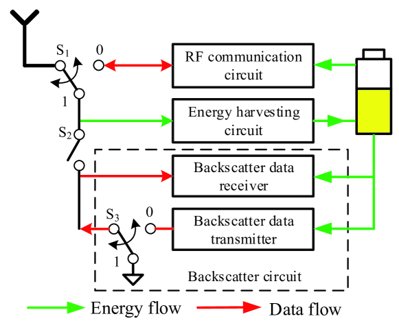
In this paper, we consider that the two WDs can transmit information in both active (RF communication) and passive modes (backscatter communication). The circuit block diagram of two users is shown in Fig. 2. With the two switches and , the two WDs can switch flexibly among three operating mode as follows.
-
1.
Backscatter Mode ( and S2 is closed): in this case, the antenna is connected to backscatter communication and energy harvesting circuits. A WD transmits information passively by backscattering the received RF signal. Specifically, a WD transmits “1” or “0” by switching S3 between reflecting or absorbing state, respectively. Accordingly, a backscatter receiver uses non-coherent detection techniques, e.g., energy detector2012:MAK , to decode the transmitted bit. Notice that the energy consumption on the operation of backscatter transmitter can be well neglected due to the harvested energy during the absorbing state 2017:DTH .
-
2.
RF Communication Mode (): the antenna is connected to the RF communication circuit and the user can transmit or receive information using conventional RF wireless communication techniques. Here, the transmission energy consumption is supplied by the RF energy harvested from the HAP.
-
3.
Energy-harvesting Mode ( and S2 is open): the antenna is connected to the energy harvesting circuit, which can convert the received RF signal to DC energy and store in a rechargeable battery. The energy is used to power the operations of all the other circuits.
2.2 Protocol Description
As shown in Fig. 1, channel estimation (CE) is first performed with a fixed duration , such that a central control point (such as the HAP) is aware of the channel coefficients . After CE, the system operates in four phases. In the first phase of duration the HAP broadcasts wireless energy in the DL with fixed transmit power , while both the WDs harvest RF energy. In the second phase of duration , the HAP continues to broadcast energy while WD1 uses its backscatter communication circuit to transmit its information to the WD2. Here, we assume the HAP neglects the backscattered signal due to the hardware constraint. Then, in the third phase, WD1 operates in the conventional RF communication mode to transmit its information, using the harvested energy to WD2. Notice that the HAP can overhear the RF transmission of WD1 during this phase. In the last phase of length , WD2 first relays the user WD1’s information to the HAP with average power over amount of time, and then transmits its own information to the HAP using its harvested energy with average power over amount of time, respectively, where . Notice that we have a total time constraint
| (1) |
For convenience, we assume in the sequel without loss of generality.
3 Throughput Performance Analysis
During the DL phase, the HAP transmits energy signal with the fixed power in amount of time. It is assumed that the energy harvested from the receiver noise is negligible. Hence, the amount of energy harvested by WD1 and WD2 can be expressed as 2016:Bii
| (2) |
where denotes the energy harvesting efficiency assumed fixed and equal for each user.
In the second stage of duration , WD1 uses backscatter communication to transmit its information to WD2. Let denote the transmitted energy signal by the HAP with . We assume a fixed backscattering data rate bits/second, thus the duration of transmitting a bit is second. In particular, when WD1 transmits a bit “0”, WD2 receives only the energy signal from the HAP
| (3) |
Otherwise, when WD1 transmits a bit “1”, the received signal at WD2 is a combination of both the HAP’s energy signal and the reflected signal from WD1, where
| (4) |
where denotes the signal attenuation coefficient due to the reflection at WD1, denotes the receiver noise at WD2.
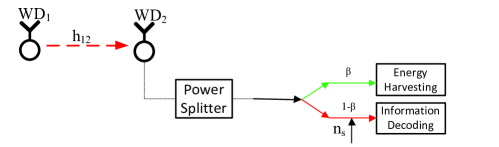
Specifically, as shown in Fig. 3, we apply a power splitting scheme, where the received RF signal is split into two parts. We denote as the splitting factor, such that part of the signal power is harvested by the device, while the rest of the signal power is used for information decoding (ID). For simplicity, is assumed a constant in this paper. The information decoding circuit introduces an additional noise , which is assumed independent of the antenna noise . Thus, the signal at energy decoder and information decoder can be expressed as
| (5) |
where when sending “0” and when sending “1”. Without loss of generality, we assume that “0” and “1” are transmitted with equal probability. The harvested energy by WD2 can be expressed as
| (6) |
Here, we assume that the signals received directly from the HAP and that reflected from WD1 are uncorrelated due the the random phase change during backscatter. Meanwhile, we assume that WD1 maintains its battery level unchanged during the backscatter stage, where the small amount of energy harvested is consumed on the on-off operations of the backscatter switches.
We denote the sampling rate of WD2’s backscatter receiver as , such that it takes samples during the transmission of a bit, either “0” or “1”. The following lemma derives the bit error probability (BER) of using an optimal energy detector to decode the received one-bit information.
Lemma 1
The BER using an optimal energy detector for the backscatter communication is
| (7) |
Proof
Due to the page limitation, the derivation is omitted here.
Then, the communication can be modeled as a binary symmetric channel, whose capacity (in bit per channel use) can be expressed as
| (8) |
Accordingly, the effective data rate from WD1 to WD2 is
| (9) |
Within the sequel amount of time, WD1 uses the harvested energy to actively transmit its information. By exhausting its harvested energy on WIT, the average transmit power of WD1 is given by
| (10) |
We denote as the complex base-band signal transmitted by WD1 with . The received signals at WD2 and the HAP in this time slot are expressed as
| (11) |
where and denote the receiver noises.
During the last time slot of duration , the WD2 first relays WD1’s message to the HAP and then transmits its own message. Specifically, we denote the transmit power and time for relaying WD1’s message as and , and those for transmitting its own message as and . Then, the total energy consumed by WD2 is constrained as
| (12) |
Denote the time allocations as , and the transmit power values . For simplicity of illustration, we assume that the receiver noise power is at all receiver antennas except for the additional noise introduced in the power splitter, whose power equals to . Then, let and denote the achievable rates of transmitting WD1’s message from WD1 to WD2, from WD1 to the HAP, and to the HAP relayed by WD2, respectively, which are given by
| (13) |
| (14) |
Thus, the achievable rate of WD1 within the time slot of length can be expressed as2014:Ju2
| (15) |
and the achievable rate of WD2 is
| (16) |
4 Common Throughput Maximization
In this paper, we focus on maximizing the minimum (max-min) throughput of the two users by jointly optimizing the time allocated to the HAP, WD1 and WD2 (), and power allocation , i.e.,
| (17) | ||||||
| s. t. | ||||||
Noticed that if we set and . Then (P1) reduces to the special case of WPCN without cooperation, i.e., the near user WD2 does not help the far user WD1 with relaying its information to the HAP.
(P1) is non-convex in the above form due to the multiplicative terms in (12). To transform (P1) into a convex problem, we introduce auxiliary variables and . With in (10), in (13)-(14) can be re-expressed as function of , and in (16) can be re-expressed as function of and , i.e.,
| (18) |
| (19) |
where , , are constant parameters.
Accordingly, by introducing another auxiliary variable , (P1) can be equivalently transformed into the following epigraph form:
| (20) | ||||||
| s. t. | ||||||
Notice that and are all concave functions (see the proof in 2014:Ju2 ), therefore (P2) is a convex optimization problem, which can be easily solved by off-the-shelf convex optimization algorithms, e.g., interior point method. Then, after obtaining the optimal and in (P2), the optimal in (P1) can be easily retrieved by setting and .
5 Simulation Results
In this section, we use simulations to evaluate the performance of the proposed cooperation method. In all simulations, we use the parameters of Powercast TX91501-1W transmitter as the energy transmitter at the HAP and those of P2110 Power harvester as the energy receiver at each WD with energy harvesting efficiency. Without loss of generality, it is assumed that the noise power is set W for all receivers, the introduced additional noise power for ID circuit in Fig. 3 is W. The channel gain , where denotes the distance separation between two devices, e.g., HAP-to-WD distance or the distance between the two WDs. denotes the antenna power gain, denotes the path-loss factor, =0.8 denotes the power splitting factor, is set as a fixed backscatter reflection coefficient and MHz denotes the carrier frequency.
Fig. 4 compares the achievable max-min throughput of different schemes when the inter-user channel varies. In this case, the HAP and the two users are assumed to lie on a straight line in which the near user WD2 is in the middle with . Here, we fix meters and vary from 6 to 10 meters. Besides, we consider two different AB communication rates kbps, 50 kbps. Evidently, the throughput performance decreases with for all the methods due to the worse inter-user channel . Besides, both user cooperation methods, either with or without AB communication, outperforms the independent transmission scheme. For the two cooperation methods, when kbps, the proposed AB-assisted cooperation outperforms the one without AB communication when , but produces worse performance otherwise. Similar result is also observed when kbps, where the proposed method has better performance when the inter-user channel is relatively weak. This is because when the far user WD1 moves more away from the HAP, it suffers from more severe attenuation in both energy harvesting and information transmission to WD2. Therefore, the optimal solution allocates more time to both WET and information exchange from WD1 to WD2 if AB communication is not used. The application of AB communication can effectively reduce the energy and time consumed on information exchange, thus can improve the overall throughput performance.
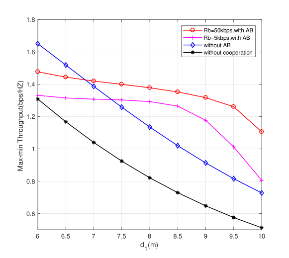
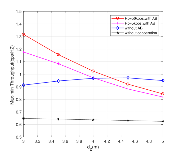
Fig. 5 shows the impact of the HAP-to-WD2 (relaying) channel to the optimal throughput performance. Here, We set meters, and vary from 3 to 5 meters. Noticed that the performance of non-cooperation scheme hardly changes as increases, this is because its throughput is mainly constrained by the weak channel between the far user WD1 to HAP. It is observed that the proposed user cooperation has better performance than the one without AB communication when the helping relay is close to the HAP ( is small). Again, this is because when is small, the separation between the two WDs is large thus the inter-user channel is weak. Therefore, WD1 needs to consume significant amount of energy if transmitting actively to the helping WD. The use of AB-assisted cooperation can effectively reduce the energy consumptions and thus improve the throughput performance. The simulation results in Fig. 4 and Fig. 5 demonstrate the advantage of applying AB communication to improve the throughput performance of user cooperation in WPCN under various practical setups, especially when the inter-user channel is relatively weak.
6 Conclusions
In this paper, we proposed a novel user cooperation method using AB communication in a two-user WPCN. In particular, we studied the maximum common throughput optimization problem of the proposed model, and proposed efficient method to obtain the optimal solution. By comparing with representative benchmark methods, we showed that the proposed AB-assisted cooperation can effectively improve the throughput fairness performance in WPCN.
References
- (1) Bi, S., Ho, C.K., Zhang, R.: Wireless powered communication: opportunities and challenges. IEEE Commun. Mag. 53(4), 117-125 (2015)
- (2) Bi, S., Zeng, Y., Zhang, R.: Wireless powered communication networks: an overview. IEEE Wireless Commun. 23(2), 10-18 (2016)
- (3) Ju, H., Zhang, R.: Throughput maximization in wireless powered communication networks. IEEE Trans. Wireless Commun. 13(1), 418-428 (2014)
- (4) Bi, S., Zhang, R.: Placement optimization of energy and information access points in wireless powered communication networks. IEEE Trans. Wireless Commun. 15(3), 2351-2364 (2016)
- (5) Bi, S., Zhang, Y.J., Zhang, R.: Distributed scheduling in wireless powered communication network: protocol design and performance analysis. in Proc. IEEE WiOpt, Paris, France. (2017)
- (6) Bi, S., Zhang, Y.J.: Computation rate maximization for wireless powered mobile-edge computing with binary computation offloading. IEEE Trans. Wireless Commun., 17(6), 4177-4190 (2018)
- (7) Bi, S., Zhang, R.: Node placement optimization in wireless powered communication networks, in Proc. IEEE GLOBECOM, San Diego, USA. (2015)
- (8) Ju, H., Zhang, R.: User cooperation in wireless powered communication networks. in Proc. IEEE GLOBECOM, Austin, TX, USA. pp.1430-1435 (2014)
- (9) Zhong, M., Bi, S., Lin, X.: User cooperation for enhanced throughput fairness in wireless powered communication networks. Springer Wireless Networks. 23(4), 1315-1330 (2017)
- (10) Yuan, L., Bi, S., Zhang, S., Lin, X., Wang, H.: Multi-antenna enabled cluster-based cooperation in wireless powered communication networks. IEEE Access. 5, 13941-13950 (2017)
- (11) Wu, Y., Chen, J., Qian, L. P., Huang, J., Shen, X. S: Energy-aware cooperative traffic offloading via device-to-device cooperations: an analytical approach. IEEE Trans. Mobile Comput. 16(1), 97-114 (2017)
- (12) Liu, V., Parks, A., Talla, V., Gollakota, S., Wetherall, D., Smith, J.R.: Ambient backscatter: wireless commumication out of thin air,” in Proc. ACM SIGCOMM. Hong Kong. pp.39-50 (2013)
- (13) Wang, G., Gao, F., Fan, R., Tellambura, C.: Ambient backscatter communication systems: detection and performance analysis. IEEE Trans. Commun. 64(11), 4836-4846 (2016)
- (14) Abdulsattar, M.A.K., Hussein, Z.A.: Energy detector with baseband sampling for cognitive radio : real-time implemention. Wireless Engineering and Technology. 3(4), 229-239 (2012)
- (15) Bi, S., Zhang, R.: Distributed charging control in broadband wireless power transfer networks. IEEE J.Sel.Areas in Commun. 34(12), 3380-3393 (2016)
- (16) Hoang, D.T., Niyato, D., Wang, P., Kim, D.I., Han, Z.: Ambient backscatter: a new approach to improve network performance for RF-powered cognitive radio networks. IEEE Trans. Commun. 65(9), 3659-3674 (2017)