Drifting Photons on Optical Paths, Mirrors, Sub-mm Resolution in Four Dimensions, and Transverse/Longitudinal Phase Space: Exploiting Psec Time Resolution
Abstract:
I discuss the status of MCP-based photo-detector amplification sections and Cherenkov light sources for precise timing measurements of charged particles and gamma rays. Sub-psec resolution is predicted for the large pulses such as those produced by a charged particle or electromagnetic shower traversing a photo-detector entrance window. Measuring events with sub-mm resolution in each of the 4 dimensions expands the optical phase space from 4 dimensions, allowing emittance transformations that can minimize expensive instrumented photo-sensitive area.
This is a talk given to a sophisticated audience of particle detector developers who understand the many challenges of inventing and bringing into routine use an innovative detector technology on a large scale. One can ask why a talk on very fast optical vacuum-tube detectors in a conference on gas-based detectors? I hope what follows elicits ideas for novel hybrid detector systems as well as for improving and exploiting timing in event reconstruction in gas-based devices.
1 Three Timing Cases to Distinguish
The factors limiting the ultimate timing resolution are different in each of the following cases:
-
1.
Single optical photons (Scintillation or Cherenkov)
-
2.
Charged particles above Cherenkov threshold (in or a glass window, for example)
-
3.
Electromagnetic showers from high energy photons.
I will talk first about the 2nd and 3rd cases, relativistic charged particles and high-energy photons, for which psec or sub-psec time resolutions are plausible given that certain detection criteria are met, before moving on to the 1st case, for which the ultimate resolutions are determined by other factors and are typically an order-of-magnitude larger.
I treat time and space distance in ‘natural’ units, i.e. , and 1 psec 300 microns; 1 nsec 1 foot. Similarly momentum is defined as (and so has the same units as energy 111As and are Lorentz 4-vectors it is natural to use the same units for all four components when discussing light (and unnatural to do otherwise)..
2 Criteria for Sub-Psec Timing
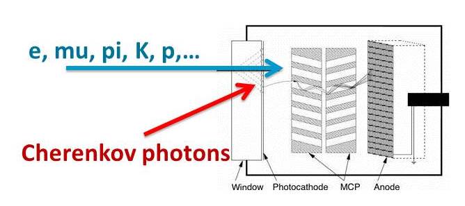
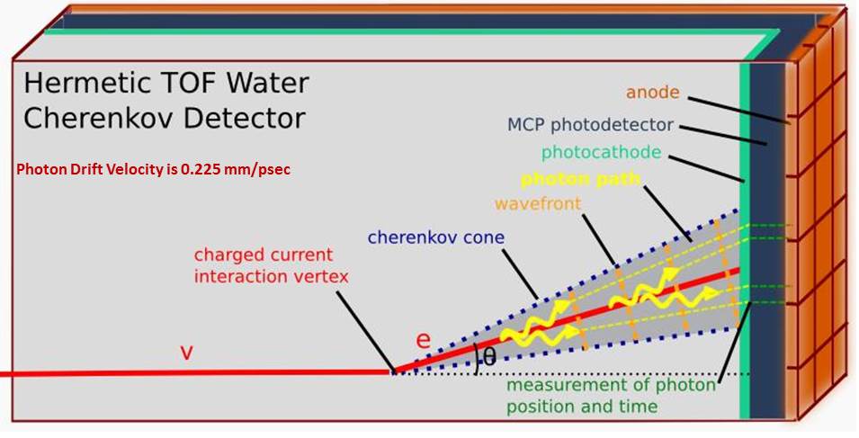
The first necessary criterion for sub-psec timing is a source of many photons in a psec time-space interval. A prime example is the Cherenkov light from a charged particle traversing a radiator or the entrance window of a photodetector [1, 2, 3, 4]. Figure 1 shows the geometry. The first light to hit the photocathode on the vacuum side of the window will be at the spot the particle exits the window, followed by photons in an expanding ring as the Cherenkov light from the path arrives at the window exit plane (assuming normal incidence- the ring shape and timing depend on the incident angle of the charged particle). A fast (coherent) pulse of photons impinging on the cathode will produce many photo-electrons in a well-defined pattern.
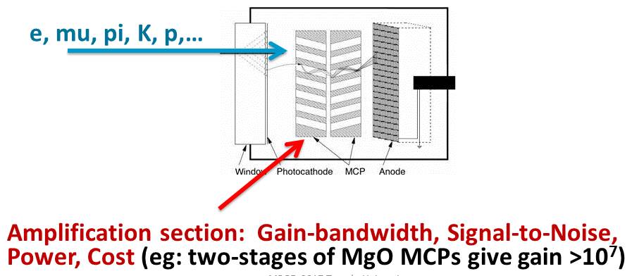
The second criterion is a homogeneous array of small pixels so that light transit times are short within one pixel. The small pixels produce a fast rise-time such as in a Micro-Channel Plate (MCP) [5]. An Incom [6] 8”-square micro-channel capillary plate has 8 20-micron pores (20 microns is 67 femtoseconds at ). Figure 2 indicates the geometry.
The third psec criterion: high-gain per pixel, is more subtle. The bright source will produce multiple photons, typically with a transit-time-spread (TTS) in the range of 50-100 picoseconds. However the first photon will have a much smaller jitter. High gain is necessary for the first photon to determine the timing of the subsequent pulse. The statistics determining the timing consequently is not Gaussian, but Poisson; the determining factor is the probability for an elapsed time from the particle traversal in which there is no photoelectron, which per unit time is , where is the average number of photoelectrons per psec. Figure 3 depicts the idea. A full simulation will be required to make this idea quantitative (See Figure 10).
3 Factors that Determine Timing Resolution and the 1 Psec ‘Barrier’
The LAPPD Collaboration was formed in 2009 to build large-area fast detectors for charged particle identification at the Fermilab Tevatron Collider and Large Hadron Collider at CERN [7]. At the first of the workshops on determining the limits in fast timing [8] there was spirited debate on the most promising techniques and the factors that limit the resolution. Subsequent development of electronics and photodetectors, and detailed measurements [9] have pushed the uncertain region down to psec (See, for example, the contributions to The Factors That Limit Time Resolution [10]).
Figure 4 shows a table from Stefan Ritt’s talk at the Second Chicago Photocathode Workshop characterizing the predicted timing resolution using waveform sampling [11] . For a fixed number of samples on the leading edge of the pulse the dependences on Signal/Noise () and bandwidth are linear. Current values are shown in the last row [12]. This is of course an extrapolation by more than an order of magnitude. However as I will show below, LAPPD data follow the rule-of-thumb down to psec and extrapolate to 1-2 psec.
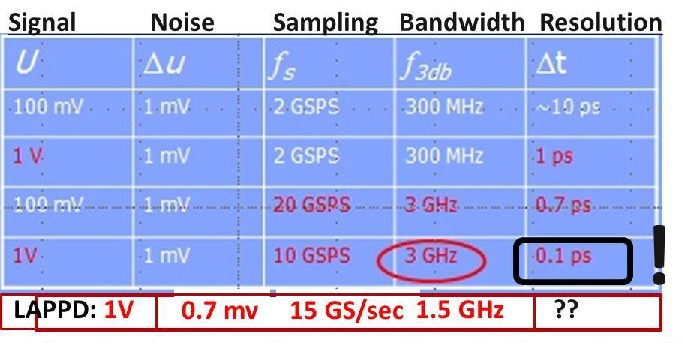
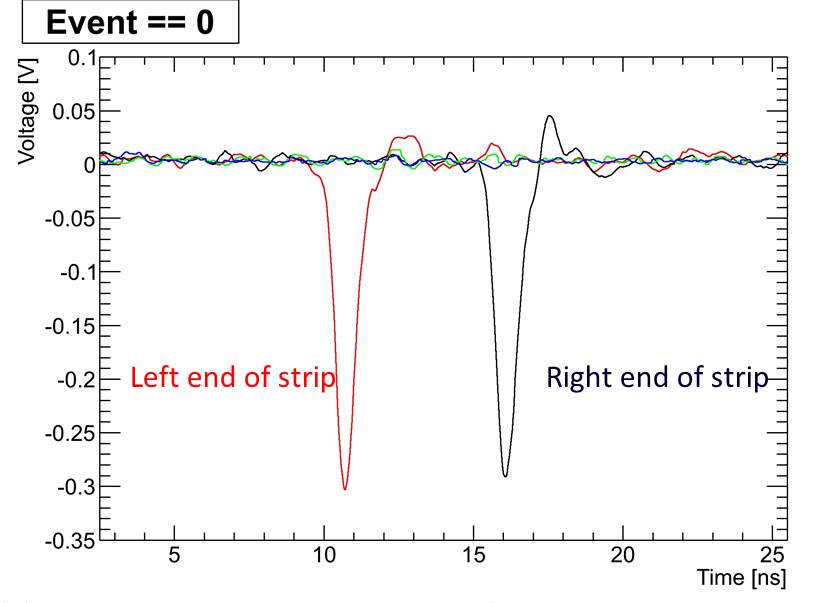
Figure 5 shows the anode pulse resulting from a fast laser pulse incident on the ‘Demountable’ LAPPDTM [13]. The photodetector anode consists of 50-ohm RF strips [14] which penetrate the hermetic package of the photodetector. The strips are read out at 10 GS/s with waveform sampling ASICs at each end of each strip. The time of the laser pulse is given by the average time of the two recorded pulses; the position by the difference in times.
4 Waveform Sampling: Oscilloscopes on Chips
The development of psec timing in real experiments in the field has to take into account systematic effects such as pile-up, baseline shifts due to lower-frequency noise, photodetector light emission and HV breakdown, and pulse slewing. The development of waveform sampling ASICS [16] leads to having the equivalent of a fast oscilloscope on each channel, and, as shown in Figure 6, is inherently more precise than a simple threshold or a Constant Fraction Discriminator [17].
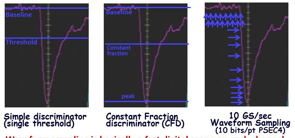
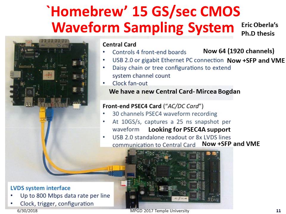
Figure 7 shows the structure of the UC PSEC4-based 10-15 Gs/sec waveform sampling system [18, 19]. The ACC control card (top left) can support up to 1920 channels in a VME crate. The current ACDC front-end card supports 30 channels of PSEC4 waveform recording at 10-15 GS/s at better than 10 bits. The Achilles heel of this version of the PSEC4 ASIC is the short buffer of 256 samples.
5 Test-bench Measurements with the LAPPD Photodetector Prototypes
The LAPPD effort [7] can be characterized as five interlinked but remarkably independent development projects: 1) a high-gain low-ion-feedback ALD-coated amplification subsystem consisting of a chevron of 20-cm MCPs; 2) a high-bandwidth (GHz) segmented anode capable of sub-mm resolution; 3) large-area bialkali photocathodes; 4) an inexpensive robust low-mass low-profile hermetic package; and 5) multi-channel low-power electronics readout capable of psec resolution. The first, second, and fifth of these lend themselves to testing ‘on the bench’ in a well-equipped laser lab [15], and have been completed to the point of manufacturability [13]. The third and fourth development efforts have been brought to the point of commercial manufacturability by Incom [6]; work continues on improved performance and manufacturability, in particular with respect to price and volume 222The photocathode effort has also led to ongoing remarkable ‘theory-based’ commercial and accelerator development programs, beyond the scope of this talk. .
Figure 8 shows the measured LAPPD timing resolution for single photo-electrons, digitized with the UC PSEC4 waveform sampling system [18, 19].
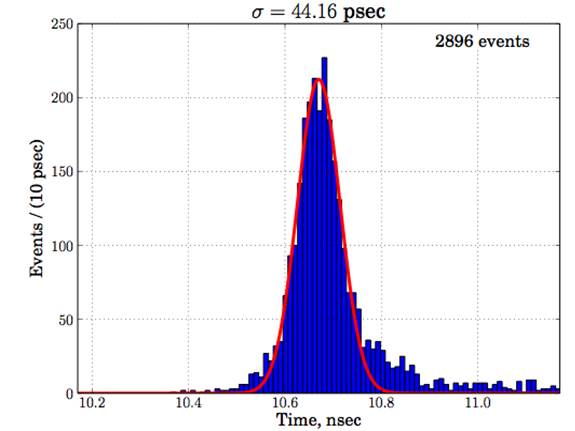
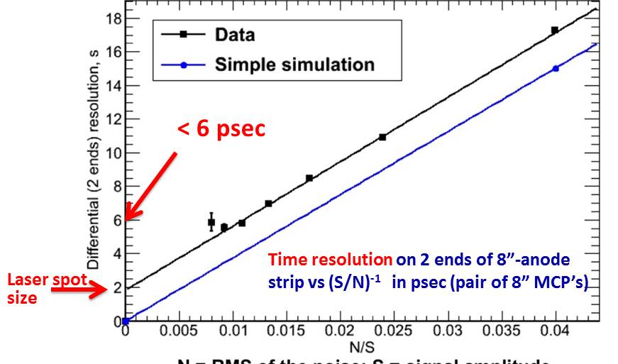
Figure 9 shows the measured time resolution with the Demountable LAPPD [13, 15]. The simple Ritt ‘rule-of-thumb’ is shown for comparison. The goal of future trials of optimized detectors in the Fermilab test beam is to test the extrapolation down to the several psec level and below, where there are presumably new processes that limit the resolution.
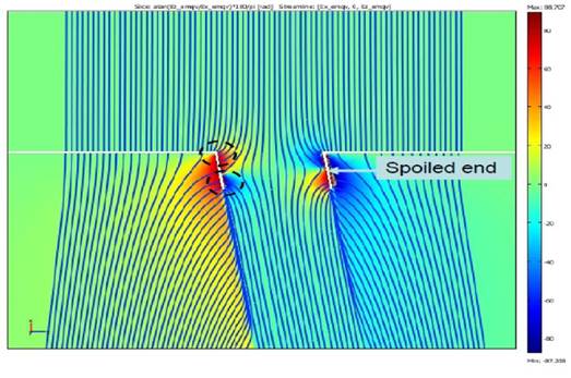
The data are consistent with the time resolution being dominated by the jitter in the ‘first strike’ of the initial photo-electron on the secondary-emitting layer of the pore. Late in the shower the number of electrons is very large and statistical fluctuations are averaged out; the first several strikes, however, can vary widely in time, dominating the transit-time spread (TTS). A simulation of the electric field in an MCP pore is shown in Figure 10, illuminating the geometry of the first strike and the jitter due to path=length differences. The jitter due to geometry can be diminished by smaller pore size, large bias angle, and higher photocathode-MCP1 voltage. However to get to psec timing one will need a large number of photo-electrons and high-enough gain so that the first of many will initiate the leading edge of the pulse. More simulation is needed.
The tests of the amplification section, anode, and electronics readout designs were done with a ‘Demountable’ detector package that used an pumped system with an O-ring seal, a metal photocathode, allowing bench tests of the full performance chain while not requiring the hermetic package and bialkali photocathode [15]. Figure 11 shows the setup in the Argonne APS laser lab.
6 Some Proposed Applications of 1 Psec Timing for Charged Particles, High-Energy Gammas
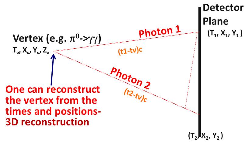
The measurement of photonic rare decay modes of K-mesons such the KOTO measurement of the neutral meson decay to pizero and neutrinos is dominated by combinatoric background in which one photon comes from one or and a second from another. Figure 12 shows the over-constrained reconstruction enabled by the precise measurement of time and position of each photon.
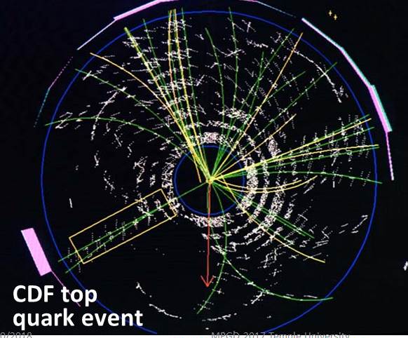
At the LHC and proposed new international high-energy colliders, a 1-psec resolution would allow identification of quark flavor for each track up to 20 GeV for s-quarks, the identification of baryons, and the association of photons and neutrons with vertices. We have proposed an internal ‘differential’ time reference - the ’clock starts’ when the photons and electrons arrive at the perimeter, and the times of arrival of heavier particles or particles from displaced vertices are measured relative to that zero. Figure 13 shows a beams-eye view of the decay of a pair of top quarks in the CDF detector at the Fermilab Tevatron, with two W bosons decaying into (presumably) or or their charge conjugate pairs, and a and quark with their distinctive flavor decay chains and multiple displaced vertices. There is a wealth of information to be had here, and possibly also in flavor-rich rare Beyond-the-Standard-Model signatures with low backgrounds due to highly suppressed Standard Model diagrams.
7 Beam Test of the First ‘Optical Time Projection Chamber’
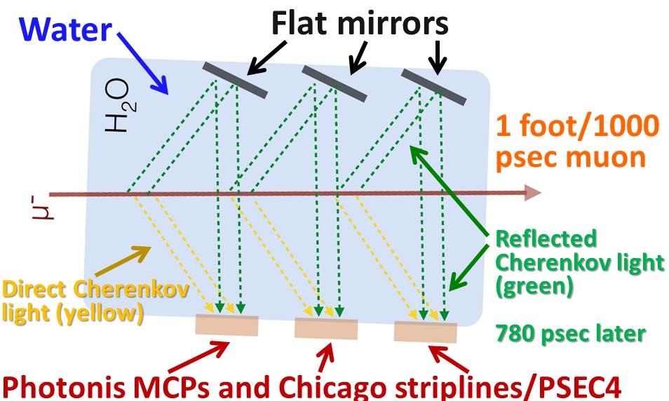
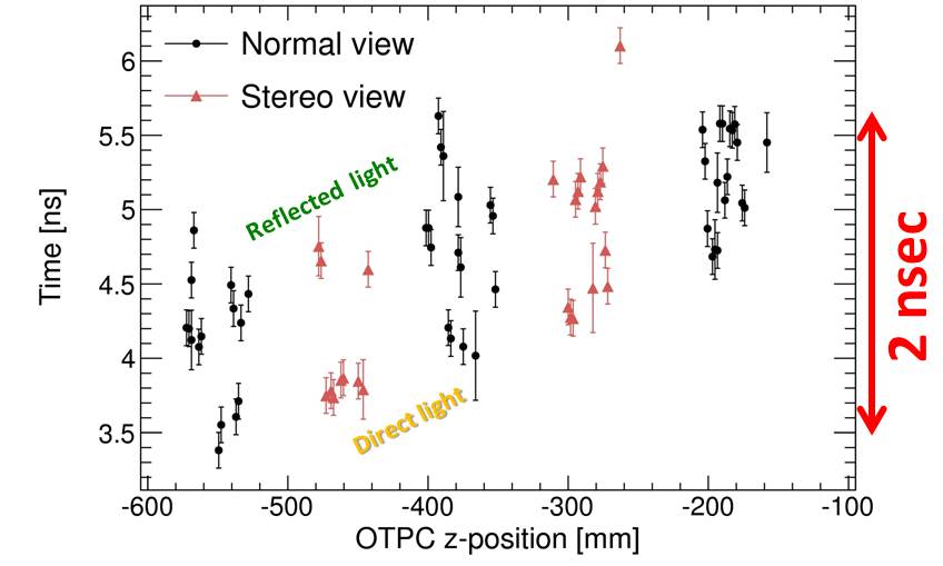
Time resolutions for single photons in the 10’s of psec allow using the photon drift time to reconstruct event topologies in 3 dimensions, in analogy to the similar use for electrons in Nygren’s Time Projection Chamber. H. Nicholson named this the ‘Optical Time Projection Chamber’, or OTPC [20]. As Cherenkov light is directional, and in the case of a charged particle traversing a liquid such as water is profuse, the technique is attractive for large liquid-based neutrino detectors [21, 22, 23, 24, 25, 26, 27].
A small OTPC prototype has been built and the technique demonstrated in the Fermilab Test Beam [28] by E. Oberla [29, 30]. An elevation view of the Optical TPC prototype is shown in Figure 14
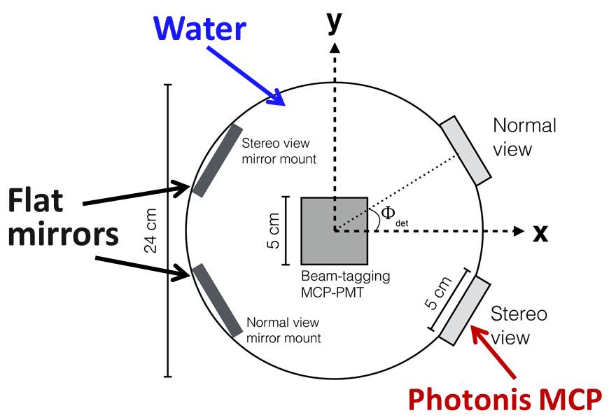
The OTPC prototype recorded tracks in stereo for 3D reconstruction with a geometry shown in Figure 15
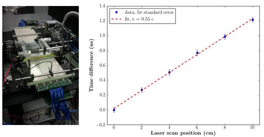
Oberla’s implementation of 50-Ohm RF strip PSEC-4 readout for the Photonis Planacon [31] used in the OTPC is shown in Figure 16. The anode pads were connected to thirty RF-strips over the 5-cm length of the Planacon. The readout was single-ended, recording the pulse at both ends of the strip from just one end, by reflecting the pulse off of an open 50-ohm line at the far end (shown as the double pulse in the figure). This minimizes channel-to-channel calibration systematics.
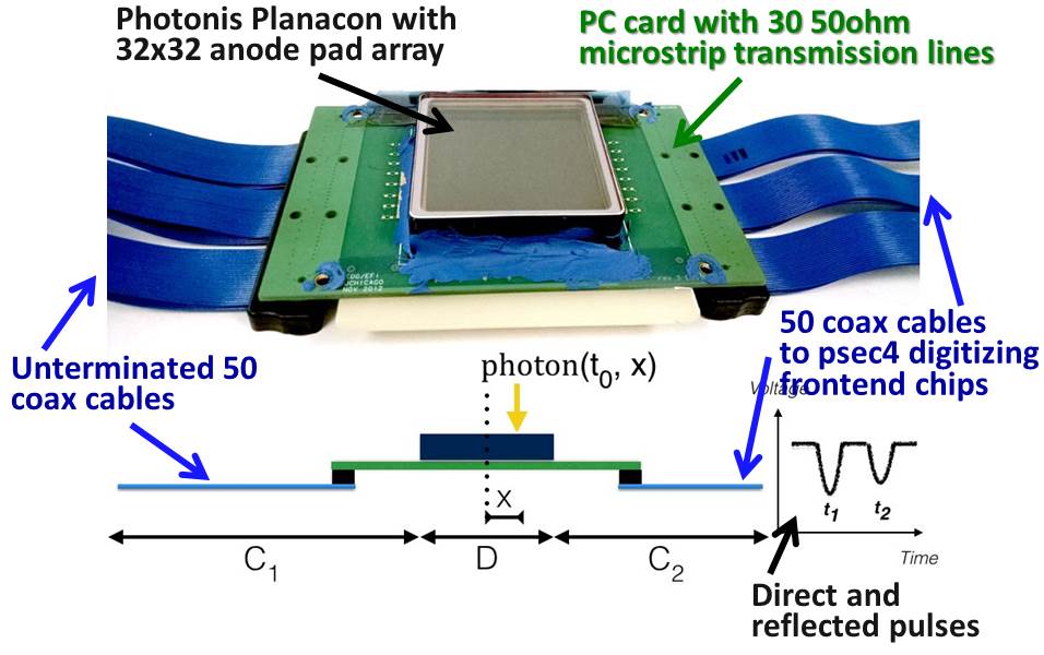
Figure 17 shows the OTPC installed in the beam at the Fermilab Test Beam Facility.
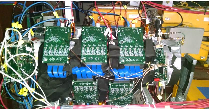
Figure 18 shows the measured time versus position along the tube for a single particle (muon) traversing the OTPC. The angular resolution is measured to be 60 mrad over a lever arm of 40 cm [29, 30].
8 New Opportunities from Exploiting Transverse-Longitudinal Phase Space
We can apply the principle of coupled time and space arrival coordinates for photons to localize and reconstruct images in more complicated geometries and applications. The use of the precise time coordinate allows working in 3D phase space, in which mirrors, baffles, lenses, and other optical devices can mix/rotate space and time. There are many interesting ideas to be had here.
8.1 Search for Neutrinoless Double Beta-Decay
The process of neutrinoless double-beta decay will occur if the neutrino is Majorana rather than Dirac. i.e. is its own anti-particle. However the predicted rate to be tested is tiny (typically on the order of years per nucleus, requiring a very large number of nuclei in the examined sample. Figure 19 shows a sketch made in the DUSEL era [32] showing the use of coupled time and space arrival coordinates in reconstructing events in large liquid neutrino detectors [20].
Because Cherenkov light is directional, it can be used to distinguish the two electrons of neutrinoless double-beta decay from solar neutrinos and other backgrounds with one electron or other signatures [21, 23, 24, 27]. Figure 20 shows results from a simulation of measuring directionality in neutrinoless double-beta decay in a 6.5m radius sphere filled with water-based liquid scintillator.

The OTPC prototype mirror configuration of Figure 14 multiplied up the effective photocathode coverage by a factor of 2. One can consider going to much larger mirror/cathode ratios (MCR) in large detectors, for which the two parameters of coverage and MCR are major factors in cost. A significant problem is dispersion for long path lengths, and may be mitigated by a geometry that provides some short-path-length data for any track in addition to more extensive coverage.
8.2 Time-of-flight Positron Emission Tomography
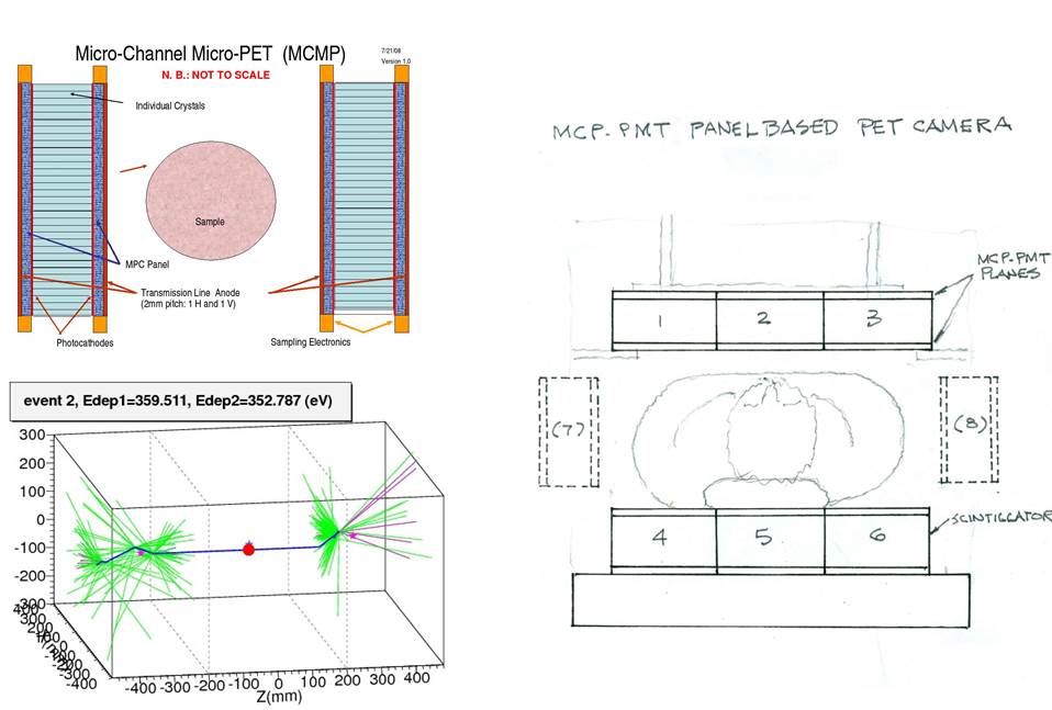
The availability of precise timing can be exploited in medical imaging, with the goal of a whole-body low-dose TOF-PET camera for post-diagnosis broad localization. Figure 21 show an implementation of a TOF-PET camera that uses LAPPD modules to locate the interactions of the two gamma rays in a liquid scintillator array.
9 Current LAPPDTM Status
Incom,Inc [6] has established a pilot production facility for modules, and recently achieved a major milestone in producing fully functional Generation-I (glass envelope) modules for commercial sale. These prototype modules, while produced in low volume, are characterized by very high gain, low noise, and useful photocathode quantum efficiency [33]. Several of these have recently been sold to ‘early adopters’, such as the ANNIE neutrino experiment at Fermilab [34], for characterization in specific applications.
At UofC we are working with Incom on ‘Gen-II’, a second generation implementation [35, 33]. The mechanical footprint is the same as for Gen-I, and the electrical properties will be the same or better as Gen-II uses the same ALD-coated microchannel plates. Innovations include changing the package from glass to alumina for robustness, stability, and higher band-width; a capacitively-coupled anode readout that moves the signal pickups outside the vacuum volume allowing for application-specific tailoring of a single module design [36]; and possibly, PMT-like photocathode ‘air-transfer’ batch production for reduced cost and higher volumes![37].
10 Acknowledgements
I thank my collaborators and technical staff at Chicago, and the remarkable group of LAPPD collaborators at ANL, Arradiance, Berkeley-SSL, Fermilab, Incom, and Hawaii. The participants in the ANL- Chicago-France series of workshops made essential contributions to the understanding of the limitations and potential of psec timing. The work at the University of Chicago was supported from the Department of Energy under awards DE-SC0008172 and DE-SC0015267, the National Science Foundation under PHY-1066014, the Driskill Foundation, and the University Physical Sciences Division. Special thanks are due to H. Marskiske and H. Nicholson, DOE Office of Science.
References
- [1] T. Credo, H. Frisch, H. Sanders, R. Schroll, and F. Tang; Picosecond Time-of-Flight Measurement for Colliders Using Cherenkov Light Proceedings of the IEEE, Rome, Italy, Oct. 2004; Nuclear Science Symposium Conference Record, 2004 IEEE, Vol. 1.
- [2] K. Inami, N. Kishimoto, Y. Enari, M. Nagamine, and T. Ohshima; A 5-ps Tof-counter with an MCP-PMT; Nucl. Instr. Meth. A560, p.303, 2006
- [3] J. Va’vra, D.W.G.S. Leith, B. Ratcliff, E. Ramberg, M. Albrow, A. Ronzhin, C. Ertley, T. Natoli, E. May, K. Byrum; Beam Test of a Time-of-Flight Detector Prototype; Nucl. Instr. Meth. A606, 404 (2009).
- [4] A. Ronzhin et al., Development of a 10 ps level time of flight system in the Fermilab Test beam facility; Nucl. Instr. Meth. A623,931(2010).
- [5] The group at Photek has built an exceptionally fast small MCP-based PMT with a 60-psec risetime; J. Milnes and J. Howorth, Photek Ltd; Proc. SPIE vol 5580 (2005) pp 730-740.
- [6] Incom Inc. Charlton Mass. See http://www.incomusa.com/
- [7] B. Adams et al.; A Brief Technical History of the Large-Area Picosecond Photodetector (LAPPD) Collaboration; ArXiV:1603.01843
- [8] There is extensive detector documentation, including links to the workshops held at Chicago, at http://psec.uchicago.edu/library/
- [9] The PSEC Document Library of papers, talks, internal notes, and patents is linked to the PSEC Library: http://psec.uchicago.edu/library/doclib
- [10] See the talks by D. Breton, E. Delanges, and S. Ritt in The Factors that Limit Time Resolution in Photodetectors; Workshop, University of Chicago, Chicago, IL; 28-29 April 2011. See http://psec.uchicago.edu/workshops/.
- [11] S. Ritt, in The Factors that Limit Time Resolution in Photodetectors; Workshop, Univ. of Chicago, Chicago, IL; 28-29 April 2011. See http://psec.uchicago.edu/workshops/ Note that of the values needed of the four parameters to achieve a time resolution of 100 fsec (the bottom row of the table of extrapolations), we have achieved or exceeded three: sampling rate, noise, and signal size. Only the analog bandwidth falls short with the present Chicago glass design.
- [12] The University of Chicago has trademarked the LAPPD 8”-square tile, with licensing to Incom, to distinguish it from smaller MCP-PMT’s and fundamentally different designs.
- [13] B.W. Adams, A. Elagin, H. Frisch, R. Obaid, E. Oberla, A. Vostrikov, R. Wagner, J. Wang, M. Wetstein; Timing Characteristics of Large Area Picosecond Photodetectors; Nucl. Inst. Meth. Phys. Res. A. , Vol. 795, pp 1-11 (Sept. 2015);
- [14] F. Tang, C. Ertley, J.-F. Genat, J. Anderson, K. Byrum, G. Drake, E. May, and G. Sellberg Transmission-Line Readout with Good Time and Space Resolutions for Planacon MCP-PMTs, in Topical Workshop on Electronics for Particle Physics, CERN, pp. 579-583, 2008
- [15] B. Adams, M. Chollet, A. Elagin, A. Vostrikov, M. Wetstein, R. Obaid, and P. Webster A Test-facility for Large-Area Microchannel Plate Detector Assemblies using a Pulsed Sub-picosecond Laser Review of Scientific Instruments 84, 061301 (2013)
- [16] Waveform sampling ASIC pioneers include S. Kleinfelder, D. Breton, E. Delanges, S. Ritt, and G. Varner; the technique, so applicable in particle physics, is now moving deeply into the commercial domain.
- [17] J.-F. Genat,G. Varner, F. Tang, H. Frisch; Signal Processing for Pico-second Resolution Timing Measurements; Nucl.Instrum.Meth.A607:387-393, (Oct 2009). e-Print:arXiv:0810.5590
- [18] E. Oberla, J.-F. Genat, H. Grabas, H. Frisch, K. Nishimura, and G Varner A 15 GSa/s, 1.5 GHz Bandwidth Waveform Digitizing ASIC, Nucl. Instr. Meth. A735, 452; Jan. 2014
- [19] M. Bogdan, H. J. Frisch, E. Oberla and M. Wetstein A Modular Data Acquisition System using the 10 GS/s PSEC4 Waveform Recording Chip; Paper for IEEE NSS/Mic RealTime 2016, Strasbourg, France Oct. 2016 ArXiV:1607.02395v1 8 Jul 2016
- [20] We thank H. Nicholson (DOE) for the evocative name as well as crucial support of the project.
- [21] T. Ypsilantis was the ’father’ of many of these ideas with his AquaRich detector: See Nuclear Instruments and Methods in Physics Research A 433,104 (1999).
- [22] R. A. Reeder et al.; NIM A334 (1993) 353-366, http://inspirehep.net/record/363416
- [23] C. Aberle, A. Elagin, H.J. Frisch, M. Wetstein, L. Winslow. Measuring Directionality in Double-Beta Decay and Neutrino Interactions with Kiloton-Scale Scintillation Detectors; Journal of Instrumentation Volume 9 (June 2014) JINST 9 P06012 doi:10.1088/1748-0221/9/06/P06012 e-Print arXiv:1307.5813
- [24] A. Elagin, H. J. Frisch, B. Naranjo, J. Ouellet, L. Winslow, T. Wongjirad; Separating Double-Beta Decay Events from Solar Neutrino Interactions in a Kiloton-Scale Liquid Scintillator Detector By Fast Timing Nucl. Inst. Meth. Phys. Res. A. (Sept. 2016);
- [25] K. Rielage et al. (the Miniclean Collaboration); Phys.Rev. C95 (2017) no.5, 055801.
- [26] M. Li, Z. Guo, M. Yeh, (Brookhaven), Z. Wang, S. Chen; Nucl.Instrum.Meth. A830 (2016) 303-308 arXiv:1511.09339; Eur.Phys.J. C77 (2017) no.12, 811
- [27] A. Elagin et al. Comparing Spherical Harmonics Analysis and Machine Learning Techniques for Double-Beta Decay Identification in a Large Liquid Scintillator Detector, XXVIII International Conference on Neutrino Physics and Astrophysics, June 2018; A. Elagin, Applying Machine Learning for Double Beta Decay Identification, THEIA Workshop, April 208.
- [28] Fermilab Test Beam Facility, Fermilab National Laboratory. See http://ftbf.fnal.gov/
-
[29]
E. Oberla and H.J. Frisch; Charged particle
tracking in a water Cherenkov optical time-projection chamber,
Nucl. Inst. Meth. Phys. Res. A. Volume 814, 1 April 2016, Pages
19-32, ISSN 0168-9002.
arXiv:1510.00947 - [30] Eric Oberla, Charged Particle Tracking in a Water Cherenkov Optical Time Projection Chamber, Ph.D Dissertation, University of Chicago, Aug. 2015
-
[31]
Photonis, PlanaconTM; see the Planacon link
at
http://www.photonis.com/en/product/. We thank Greg Sellberg for his development of the technique to connect the 1024 anode pads to the strips. - [32] The LAPPD project received a proposal from a large company with detector experience to commercialize the LAPPD design for the DUSEL neutrino detector. The proposal was to produce 7000 units per year, upgrading after several years to 21,000 per year. The proposal included a detailed schedule and costing. It was abandoned when DUSEL was canceled. See, for example, A. Lankford, Status of the NRC DUSEL Study, http://science.energy.gov/hep/hepap/meetings/previous-meetings/hepap-agenda-june-2011/
- [33] M. Minot, Proceedings of the 14th Pisa Meeting on Advanced Detectors, May 2018; to be published
-
[34]
See http://annie.uchicago.edu and
http://annie.uchicago.edu/lib/exe/fetch.phpmediapacmeeting_v2.1.pdf - [35] A. Elagin, Proceedings of the 14th Pisa Meeting on Advanced Detectors, May 2018; to be published
- [36] E. Angelico, T. Seiss, B.W. Adams, A. Elagin, H. Frisch, E. Oberla, E. Spieglan; Capacitively coupled Pulse Readout in a 20cm20cm MCP-based photodetector Nucl. Instr. Meth. A, 2016
- [37] H. Frisch, talk at CPAD, Albuquerque NM; Oct. 13, 2017