Spin superfluid Josephson oscillator
Abstract
The magnetic analogue of the Josephson effect can be exploited to develop a new class of nano-spin oscillators that we denote as spin superfluid Josephson oscillators. Such a device, consisting of two exchange coupled easy-plane metallic ferromagnets separated by a thin normal metal spacer, is proposed and analyzed. A spin chemical potential difference drives a precession of the in-plane magnetization of each ferromagnet. The precession angle gives maximum values of the giant magnetoresistance, resulting in large output power compared to conventional spin Hall oscillators. An applied ac current results in a time-averaged magnetoresistance with Shapiro-like steps. The multistate mode-locking behavior exhibited by the spin Shapiro steps may be explored for applications in neuromorphic computing. As an experimental characterization method, electrical measurements of spin superfluid Josephson junctions can provide additional signatures of spin superfluidity.
I Introduction
One of the goals of spintronics is the transport of spin with minimal losses. In magnetic insulators with spontaneously broken U(1) symmetry, almost dissipationless longitudinal spin transport can result from the collective excitations of the ground state Halperin and Hohenberg (1969); Sonin (2010). Such a spin current decays algebraically over distance Sonin (2010); Takei and Tserkovnyak (2014), which, in comparison to the exponential decay of magnon mediated spin currents Zhang and Zhang (2012), makes it attractive for long distance spin transport. The spin current in this state is carried by a metastable static spin spiral texture with phase winding, much like phase slips in superfluids. This spin superfluid transport in easy-plane ferromagnets (FMs) and antiferromagnets (AFMs) König et al. (2001); Sun and Xie (2013); Takei and Tserkovnyak (2014); Chen et al. (2014); Takei et al. (2014) is formally similar to mass or charge currents in superfluids or superconductors. Experimental evidence consistent with spin superfluid transport in a graphene quantum Hall antiferromagnet was recently reported Stepanov et al. (2018). A natural extension of this idea is the magnetic analogue of the Josephson effect Josephson (1962); Nogueira and Bennemann (2004); Schilling and Grundmann (2012); Hill et al. (2018).
This spin superfluid Josephson effect can be harnessed to develop a new class of nano-spin oscillators that we denote as spin superfluid Josephson oscillators (SSJOs). Spin oscillators convert dc electric current into non-linear magnetization precession Katine et al. (2000); Sun (1999); Tsoi et al. (1998); Kiselev et al. (2003); Rippard et al. (2004); Krivorotov et al. (2005), which can be detected from the magnetoresistance. Persistent magnetization oscillations can also be induced in ferromagnetic insulators (FMI) and antiferromagnetic insulators (AFMI). In these systems, a pure spin current, injected via the spin Hall effect (SHE) from an adjacent heavy metal (HM) Collet et al. (2016); Hamadeh et al. (2014), causes magnetization dynamics in the FMI or AFMI layer. Recently, a SSJO was proposed using exchange coupled AFMIs Liu et al. (2016). While AFMIs have low damping, negligible dipolar coupling, and THz frequencies, the a.c. output power of the AFMI SSJO is low. Here, we demonstrate an easy-plane metallic FM SSJO that exhibits large output power compared to that of conventional spin oscillators.
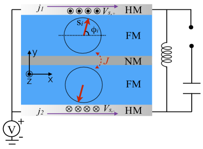
The SSJO illustrated in Fig. 1 consists of two easy-plane FMs with an antiferromagnetic interlayer exchange coupling. This is the magnetic analogue of a -phase Josephson junction. Electrical current along the x-direction in the HM generates a transverse spin current across the junction. Using both the Landau-Lifshitz-Gilbert (LLG) equation and micromagnetic simulations, we show that this current drives steady-state spin oscillations within the junction with a frequency determined by the applied current and the parameters of the spin superfluid Josephson (SSJ) junction. These spin oscillations result from rotations of the in-plane magnetization of the easy-plane FMs.
The SSJ produces a novel magnetoresistance (MR) effect, hereafter called SSJ-MR, which is the only contribution in insulating devices. In metallic systems, the MR signal induced by the phase rotation has an additional contribution from the giant magnetoresistance (GMR) effect. The global 2 precession of the in-plane magnetization results in large output power of the SSJO. When connected with an ac current, the time-averaged SSJ-MR exhibits Shapiro steps as a function of the applied current’s dc component. The SSJ-MR exhibits a step when the ac driving frequency matches the characteristic frequency of the SSJO.
II Theoretical Model
The SSJO shown in Fig. 1 consists of two HM contacts and two easy-plane FMs separated by a thin non-magnetic spacer. The Hamiltonian for this system can be expressed as,
where is the volume, is the interlayer exchange coupling between the two easy-plane FMs, and and represent the spin stiffness and easy-plane anisotropy of the FM, respectively. denotes the spin orientation of each easy-plane FM, denotes the top (bottom) FM, and is the saturated spin density. For simplicity, we assume the device to be symmetric around the center of the NM layer so that the layer thicknesses, interfaces, and material parameters in the top half of the SSJO are identical to those in the bottom half. In Eq. (II), the easy-plane anisotropy () ensures that the energy of each FM is independent of the in-plane magnetization direction (indicating symmetry). The energy is minimized by the in-plane spin configuration, with a fixed in-plane magnetization angle ().
For the in-plane spin configuration, the last term in Eq. (II) becomes an oscillatory function of the relative angle of the in-plane magnetization. The interlayer exchange coupling can be AFM () or FM (). This depends on the material and geometrical parameters Parkin et al. (1990). For , spins in the top and bottom easy-plane FMs point in opposite directions cancelling the dipolar interactions. It has been shown that dipolar interactions in easy plane FMs can break the easy-plane U(1) symmetry which destroys spin superfluidity in long distance spin transport Skarsvåg et al. (2015). Hereafter, for simplicity, we assume an AFM type interlayer exchange coupling and neglect dipolar interactions.
The long wavelength magnetization dynamics of the device heterostructure can be captured by the Landau-Lifshitz-Gilbert (LLG) equation,
where denotes the time derivative of , is the damping constant and describes the spin torque and spin pumping effect at the HM/FM interfaces. To induce the spin oscillations, a spin current with polarization perpendicular to the easy-plane, can be used to produce a spin transfer torque on the in-plane magnetization. This spin current is generated by driving an electrical current in the x-direction in the HM contacts via the SHE. Decomposing, , the dynamics of both FMs can be expressed in terms of canonically conjugate amplitude and phase variables, and . For small variation of the out-of-plane magnetization, , the LLG equation can be expanded to the lowest order in and ,
| (3) |
where we assume that is perpendicular to the easy plane. We take the single domain approximation of magnetization dynamics across the junction, and hereafter neglect the spatial dependence of the fields and set .
Defining as the relative phase, as the total spin torque across the junction and as the relative out-of-plane magnetization, the equation of motion can be reduced into two equations that describe the dynamics of the relative coupled variables,
| (4) | |||||
For zero damping and zero spin torque (), the above equations resemble the -phase Josephson junction of weak link superconductors with characteristic frequency Liu et al. (2016).

III Dynamics with dc input
When biased as shown in Fig. 1, the two HMs are connected in a parallel circuit configuration with currents flowing in the same direction (x-direction). The current flowing through the HM contacts generates a spin chemical potential, with spins perpendicular to the easy plane. To determine the electric and magnetic dynamics in the circuit, we solve for their dynamics self-consistently in the device heterostructure. The spin torque at the HM/FM interface can be expressed as,
| (5) |
where , denotes the non-equilibrium spin accumulation at the top and bottom interface. is the effective spin mixing conductance, where is the interface area, is the real part of the spin mixing conductance and N is the total number of spins. We assume the spin mixing conductance to be purely real through out this paper. The first term in Eq. 5 is the spin torque exerted due to the injected spin current. The second term is the reciprocal spin pumping effect Tserkovnyak et al. (2002) due to the precession of the magnetization in the FMs. This term must be included to satisfy Onsager’s reciprocity relations.
With the circuit set up above, we have , where the spin chemical potential . Inserting this relationship into Eq. (3) and eliminating , we get the equation of motion for Liu et al. (2016),
| (6) |
where is the enhanced damping. This equation is the same as the RCSJ model for superconducting Josephson junctions with an effective Stewart-McCumber parameter McCumber (1968); Stewart (1968). Because of the Gilbert damping a critical spin chemical potential , which is related to the current density in the HM contacts, is required to excite a magnetization oscillation. In the strong damping regime (), the critical spin chemical potential required to induce a persistent oscillation is . In the intermediate damping regime (), the critical spin chemical potential can be estimated as , which depends on the damping, the interlayer exchange coupling and the FM easy-plane.
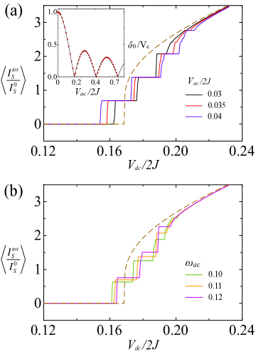
To determine the magnetization dynamics, we perform both micromagnetic simulations (red dots in Fig. 2 (b)) and numerical calculations of the RCSJ model (solid line in Fig. 2 (b)) for the SSJ junction. The micromagnetic simulations were performed on two exchange coupled easy-plane FMs with dimensions 200 nm 200 nm 5 nm. The saturation magnetization in micromagnetic simulations is kA/m and the parameters for Eq. (II) are meV, meV, eV, and . In steady-state, oscillates around a finite time-averaged value. These oscillations correspond to rotation of the relative in-plane magnetization. Comparison of the micromagnetic simulations validates our Hamiltonian and the RCSJ model.
Above the critical voltage , the oscillation frequency depends on the applied voltage . To investigate the relationship, we plot the oscillation frequency as a function of the normalized spin chemical potential for three different damping constants in Fig. 2. Within this damping regime, the frequency has a quasi linear relationship with which is independent of damping. In the strong damping regime (), one can analytically solve Eq. (6) and obtain a time-dependent solution for with an oscillation frequency . This is consistent with our numerical calculations of the RCSJ model.
IV Dynamics with ac input
The spin oscillations also exhibit Shapiro step like dynamics in the presence of an ac input Shapiro (1963). An ac spin chemical potential of the form of can be induced by an ac electric current in the HMs. In a simple model, when is an integer multiple of , mode-locking of the input signal and the magnetization dynamics can occur. This results in a Shapiro step like behavior in the time averaged pumped spin current within the HM. The dynamics of the system with ac input are determined by solving Eq. (6) with a time dependent source .
In order to explore the role of and , we calculate the time averaged as a function of . The results for different and are shown in Fig. 3(a) and Fig. 3(b), respectively. The normalized spin current is plotted where is the characteristic spin current associated with the SSJ junction. When , the time averaged - shows a non-linear relationship with Liu et al. (2016). After increasing to a finite value, the - curve shows several steps, in the averaged spin current.
At each step, the oscillation frequency and maximum oscillation amplitude depends on . The step position in the time averaged has a complicated dependence on , and . Both and strongly influence the d.c. critical value and the step width, whereas the step height only depends on . As shown in Fig. 3, finite can reduce the critical value required for a persistent oscillation. Furthermore, the width of the step as a function of is proportional to the Bessel function of the first kind , which is characteristic of the Shapiro steps Shapiro et al. (1964) in superconducting Josephson junctions. The magnetization dynamics of the SSJOs generate a novel magnetoresistance that we discuss in the next section.
V Output Power
Spin pumping generates an additional electromotive force,
| (7) |
where denotes the top and bottom HM contacts with thickness . is the effective spin Hall angle that takes into account the thickness effect of the HM. The current in the HM contacts is modified to , where the first term is the applied field, is the resistivity and is the electrical current density. Eq. (7) indicates that the magnetization dynamics generate an internal electromotive force which can be detected as magnetoresistance. Therefore, the SSJ oscillations can be detected by purely electrical means.
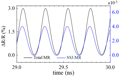
One can apply Eq. (7) to the device geometry in Fig. 1 and determine the MR response. We restrict our analysis to the -component of , since the -component of is small. For , we find . According to Eq. (7), is directly proportional to . Thus, the dynamics of gives a time-dependent contribution, which results in an effective MR of the circuit with an oscillation frequency . The SSJ-MR with a d.c. electric current source in the HM contacts is plotted in the Fig. 4. The magnitude of the SSJ-MR signal is primarily determined by the spin-Hall angle .
In metallic SSJOs, which consist of two easy-plane FM metals, additional contributions due to the in-plane giant magnetoresistance (GMR) dominate the MR signal McGuire and Potter (1975); Campbell (1970); Binasch et al. (1989); Baibich et al. (1988); Hütten et al. (1999). The GMR contribution, , can be large owing to the global precession of the in-plane magnetization. To estimate the total MR, we consider a device with an area of 200 nm by 50 nm in the plane as defined in Fig. 1. The junction consists of two 3 nm thick metallic easy-plane FMs separated by a 2 nm non-magnetic metal and sandwiched by two 5 nm Pt contacts, corresponding to the geometry shown in Fig. 1. Using the following parameters, effective spin Hall angle of Pt , sheet resistance of Pt , interfacial spin mixing conductance , GMR ratio of 15%, and sheet resistance of the junction, Egelhoff et al. (1996), we calculate the resistance change for both the GMR and SSJ-MR. The total MR for metallic SSJOs with a d.c. source, plotted in Fig 4, is three orders of magnitude larger than the MR in insulating SSJOs. Here, due to the SSJ junction dimensions and large resistance of the FM layers, the contribution due to the anisotropic magnetoresistance (AMR) can be ignored.
MR signals are commonly employed to estimate the output power of a spin torque nano-oscillator. For the SSJOs, the magnetization dynamics within the easy-plane could potentially enhance the output power of the proposed device. In metallic SSJ junctions the full precession angle provides access to the maximum values of the GMR for a given . The output power for a load ranges from 200 nW to 280 nW, depending on the GMR ratio, roughly an order of magnitude larger than other spin Hall oscillators.
Shapiro steps can still be detected for metallic SSJ junctions in the time averaged . Since the amplitude of does not depend on , the time averaged contribution due to GMR is zero. Thus, even in a metallic system, the non-linear - and the Shapiro-step behavior still persists and is not buried by the large GMR effect.
Easy-plane anisotropy can be realized in FM thin films, but injecting spin polarization normal to the easy-plane via the SHE is challenging. One scheme is to create an easy-plane perpendicular to the sample plane (- plane) as shown in Fig. 1. It has been shown that such an easy-plane can be engineered in Co/Ni by combining the shape anisotropy and an easy-axis magnetic anisotropy Safranski et al. . In a sample geometry with a specific aspect ratio, such as a nanowire, an easy-axis lies along the nanowire direction (-axis) due to the shape anisotropy. By carefully tuning an easy-axis anisotropy perpendicular to the nanowire (-axis), the out-of-plane anistropy induced by the dipole interaction can be fully canceled leaving an easy-plane perpendicular to the -axis.
VI Conclusion
A new type of spin nano-oscillator based on a SSJ effect is proposed and analyzed.
A spin chemical potential difference across the junction drives planar magnetization rotation.
This spin oscillation is mediated by a spin superfluid mode and directly related to the phase difference between the two FMs.
The oscillation frequency is tuned by the interlayer exchange and the spin chemical potential.
The output power is enhanced by the GMR effect in metallic SSJ junctions.
The precession angle of the spin superfluid mode maximizes the GMR effect,
thus opening an alternate route towards building high power spin oscillators.
The multi-state mode-locking behavior exhibited by the spin Shapiro steps may also be exploited for applications in neuromorphic computing.
As an experimental characterization method,
electrical measurements of SSJ junctions can provide additional signatures of spin superfluidity.
Acknowledgements: This work was supported as part of the Spins and Heat in Nanoscale Electronic Systems (SHINES) an Energy Frontier Research Center funded by the U.S. Department of Energy, Office of Science, Basic Energy Sciences under Award No. DE-SC0012670.
References
- Halperin and Hohenberg (1969) B. I. Halperin and P. C. Hohenberg, Phys. Rev. 188, 898 (1969).
- Sonin (2010) E. Sonin, Advances in Physics 59, 181 (2010).
- Takei and Tserkovnyak (2014) S. Takei and Y. Tserkovnyak, Phys. Rev. Lett. 112, 227201 (2014).
- Zhang and Zhang (2012) S. S.-L. Zhang and S. Zhang, Phys. Rev. Lett. 109, 096603 (2012).
- König et al. (2001) J. König, M. C. Bønsager, and A. H. MacDonald, Phys. Rev. Lett. 87, 187202 (2001).
- Sun and Xie (2013) Q.-f. Sun and X. C. Xie, Phys. Rev. B 87, 245427 (2013).
- Chen et al. (2014) H. Chen, A. D. Kent, A. H. MacDonald, and I. Sodemann, Phys. Rev. B 90, 220401 (2014).
- Takei et al. (2014) S. Takei, B. I. Halperin, A. Yacoby, and Y. Tserkovnyak, Phys. Rev. B 90, 094408 (2014).
- Stepanov et al. (2018) P. Stepanov, S. Che, D. Shcherbakov, J. Yang, K. Thilahar, G. Voigt, M. W. Bockrath, D. Smirnov, K. Watanabe, T. Taniguchi, R. K. Lake, Y. Barlas, A. H. MacDonald, and C. N. Lau, arXiv:1801.07290 [cond-mat] (2018), arXiv: 1801.07290.
- Josephson (1962) B. D. Josephson, Physics Letters 1, 251 (1962).
- Nogueira and Bennemann (2004) F. S. Nogueira and K.-H. Bennemann, Europhys. Lett. 67, 620 (2004).
- Schilling and Grundmann (2012) A. Schilling and H. Grundmann, Ann. Phys. 327, 2301 (2012).
- Hill et al. (2018) D. Hill, S.-K. Kim, and Y. Tserkovnyak, arXiv.1802.04229 (2018).
- Katine et al. (2000) J. A. Katine, F. J. Albert, R. A. Buhrman, E. B. Myers, and D. C. Ralph, Phys. Rev. Lett. 84, 3149 (2000).
- Sun (1999) J. Z. Sun, Journal of Magnetism and Magnetic Materials 202, 157 (1999).
- Tsoi et al. (1998) M. Tsoi, A. G. M. Jansen, J. Bass, W.-C. Chiang, M. Seck, V. Tsoi, and P. Wyder, Phys. Rev. Lett. 80, 4281 (1998).
- Kiselev et al. (2003) S. I. Kiselev, J. C. Sankey, I. N. Krivorotov, N. C. Emley, R. J. Schoelkopf, R. A. Buhrman, and D. C. Ralph, Nature 425, 380 (2003).
- Rippard et al. (2004) W. H. Rippard, M. R. Pufall, S. Kaka, S. E. Russek, and T. J. Silva, Phys. Rev. Lett. 92, 027201 (2004).
- Krivorotov et al. (2005) I. N. Krivorotov, N. C. Emley, J. C. Sankey, S. I. Kiselev, D. C. Ralph, and R. A. Buhrman, Science 307, 228 (2005).
- Collet et al. (2016) M. Collet, X. d. Milly, O. d. Kelly, V. V. Naletov, R. Bernard, P. Bortolotti, J. B. Youssef, V. E. Demidov, S. O. Demokritov, J. L. Prieto, M. Muñoz, V. Cros, A. Anane, G. d. Loubens, and O. Klein, Nature Communications 7, 10377 (2016).
- Hamadeh et al. (2014) A. Hamadeh, O. d’Allivy Kelly, C. Hahn, H. Meley, R. Bernard, A. Molpeceres, V. Naletov, M. Viret, A. Anane, V. Cros, S. Demokritov, J. Prieto, M. Muñoz, G. de Loubens, and O. Klein, Phys. Rev. Lett. 113, 197203 (2014).
- Liu et al. (2016) Y. Liu, G. Yin, J. Zang, R. K. Lake, and Y. Barlas, Phys. Rev. B 94, 094434 (2016).
- Parkin et al. (1990) S. S. P. Parkin, N. More, and K. P. Roche, Phys. Rev. Lett. 64, 2304 (1990).
- Skarsvåg et al. (2015) H. Skarsvåg, C. Holmqvist, and A. Brataas, Phys. Rev. Lett. 115, 237201 (2015).
- Tserkovnyak et al. (2002) Y. Tserkovnyak, A. Brataas, and G. E. W. Bauer, Phys. Rev. Lett. 88, 117601 (2002).
- McCumber (1968) D. E. McCumber, Journal of Applied Physics 39, 3113 (1968).
- Stewart (1968) W. C. Stewart, Appl. Phys. Lett. 12, 277 (1968).
- Shapiro (1963) S. Shapiro, Phys. Rev. Lett. 11, 80 (1963).
- Shapiro et al. (1964) S. Shapiro, A. R. Janus, and S. Holly, Rev. Mod. Phys. 36, 223 (1964).
- McGuire and Potter (1975) T. McGuire and R. Potter, IEEE Transactions on Magnetics 11, 1018 (1975).
- Campbell (1970) I. A. Campbell, Phys. Rev. Lett. 24, 269 (1970).
- Binasch et al. (1989) G. Binasch, P. Grünberg, F. Saurenbach, and W. Zinn, Phys. Rev. B 39, 4828 (1989).
- Baibich et al. (1988) M. N. Baibich, J. M. Broto, A. Fert, F. Nguyen Van Dau, F. Petroff, P. Etienne, G. Creuzet, A. Friederich, and J. Chazelas, Phys. Rev. Lett. 61, 2472 (1988).
- Hütten et al. (1999) A. Hütten, S. Mrozek, S. Heitmann, T. Hempel, H. Brückl, and G. Reiss, Acta Materialia 47, 4245 (1999).
- Egelhoff et al. (1996) W. F. Egelhoff, P. J. Chen, C. J. Powell, M. D. Stiles, R. D. McMichael, C. Lin, J. M. Sivertsen, J. H. Judy, K. Takano, A. E. Berkowitz, T. C. Anthony, and J. A. Brug, Journal of Applied Physics 79, 5277 (1996).
- (36) C. Safranski, E. Montoya, A. Smith, J.-R. Chen, and I. Krivorotov, in Bulletin of the American Physical Society (American Physical Society).