Intrinsic Stabilization of the Drive Beam in Plasma Wakefield Accelerators
Abstract
The hose instability of the drive beam constitutes a major challenge for the stable operation of plasma wakefield accelerators (PWFAs). In this work, we show that drive beams with a transverse size comparable to the plasma blowout radius generate a wake with a varying focusing along the beam, which leads to a rapid detuning of the slice-betatron oscillations and suppresses the instability. This intrinsic stabilization principle provides an applicable and effective method for the suppression of the hosing of the drive beam and allows for a stable acceleration process.
In plasma wakefield accelerators (PWFAs), highly relativistic particle beams are used to excite plasma wakes which carry extreme accelerating fields Veksler1956 . The accelerating gradients surpass those produced in today’s conventional particle accelerators by orders of magnitude and therefore, PWFAs constitute an attractive solution for the miniaturization of the future particle acceleration technology and its derived applications.
Operating PWFAs in the blowout regime Rosenzweig1991 enables injection methods for the production of high-quality witness beams Oz2007 ; Hidding2012 ; MartinezdelaOssa2013 ; MartinezdelaOssa2015 ; Wittig2015 ; MartinezdelaOssa2017 and the efficient acceleration within the plasma wake Lotov2005 ; Tzoufras2008 . However, due to the extreme focusing fields in the blowout plasma cavity, the drive and witness beams in PWFAs are subject to transverse instabilities with large growth rates. In particular, the hose instability (HI) of the drive beam constitutes a major challenge for the optimal operation of PWFAs Huang2007 . The HI is initiated by a transverse deviation of the centroid of the drive beam which causes a displacement of the center of the focusing ion-channel, which in turn feeds back into the trailing part of the beam, leading to the resonant build-up of the transverse centroid oscillations. It was recently shown that the inherent drive beam energy loss detunes the betatron oscillations of beam electrons and thereby mitigates the HI Mehrling2017 . Still, for drive beams with a substantial hosing seed, beam break-up can occur before this mitigation mechanism becomes effective.
In this Letter, we show by means of analytical theory and particle-in-cell (PIC) simulations with HiPACE Mehrling2014 , that drive beams with a transverse size comparable to the plasma blowout radius generate a wake with a varying focusing along the drive beam, which causes a rapid detuning of the centroid oscillations and suppresses the HI. Still, the plasma blowout is completely formed in regions behind the drive beam, and therefore, the witness beams can be efficiently accelerated with no emittance degradation. The damping effect caused by head-to-tail variations of the betatron frequency is well known in radio frequency accelerators Balakin1983 ; Stupakov1997 ; Bohn2000 , and it has been recently shown to apply in the linear regime of plasma wakefield acceleration Vieira2014 ; Lehe2017 for the mitigation of the HI. In this work, we show for the first time that this stabilization principle is compatible with the blowout regime for sufficiently wide, high-current and moderate-length drive beams. The blowout regime is the most common regime in PWFAs, and therefore, this work is of crucial interest to understand why the hosing of the drive beam was avoided in FACET Hogan2010 and how it can be further suppressed in future PWFA experiments Aschikhin2016 ; Yakimenko2016 ; Heinemann2017 .
We start by considering a relativistic electron beam entering an initially neutral and homogeneous plasma. As the beam propagates through the plasma, it expels plasma electrons by means of its space-charge fields, generating in this way a plasma wakefield which propagates at the velocity of the beam. The generated wakefields exert a force on the beam electrons, where is the momentum of a beam electron, the elementary charge, the wakefield and the speed of light. Expressions for the wakefield have been derived in the linear Chen1987 ; Keinigs1987 and the blowout regime of PWFAs Lotov2004 ; Lu2006 , for axisymmetric drivers and assuming a quasi-static plasma response. The quasi-static approximation assumes that the fields and currents of the beam are frozen, or quasi-static, during the plasma evolution in the comoving frame, i.e. for these quantities, with , denoting the comoving variable. Under this approximation, it is found from Maxwell equations that the wakefields satisfy the following relations, , and , with the plasma frequency, and the unperturbed and perturbed plasma electron density, respectively, and () the longitudinal (transverse) plasma electron current. Ions are assumed to be immobile and the transverse beam current to be negligible. Beams with an electron density higher than expel essentially all plasma electrons near the propagation axis forming a homogeneous ion cavity, delimited by a sheath of plasma electrons. The maximum distance of this sheath with respect to the beam propagation axis is commonly referred as the blowout radius, . Inside this ion cavity (or blowout) we have that and , and the equation of motion for the beam-electrons can be written as
| (1) |
where both the focusing strength, , and the rate of energy change, , are constant for beam electrons at a fixed -position, and . When the blowout is not complete and the charge of the ions is partially screened by the plasma electron density, i.e. , for a non-relativistic plasma response in the region of the beam. Assuming constant with the radius for regions sufficiently close to the propagation axis, Eq. (1) is still applicable to the beam-electrons within a partial blowout, where now obtains a -dependency through . Eq. (1) describes the transverse betatron oscillations of the beam-electrons, with a frequency . Given that is a slowly varying function Kostyukov2004 , i.e. , analytical solutions to Eq. (1) can be given in the following form
| (2) |
with , the initial transverse velocity of the electron, , the initial betatron frequency, , the amplitude modulation, and , the phase advance. When and do not change with time, the phase advance can be written explicitly as
| (3) |
which for yields . We now consider an infinitesimal -slice of the drive beam, with an initial phase-space distribution . Since for all electrons within the -slice, it is straightforward to find an equation for the transverse centroid , by taking corresponding averages of Eq. (2). The resulting equation for has the same functional dependence as Eq. (2), and therefore, the beam centroids also describe betatron oscillations with frequency and amplitude , where and denote the initial transverse displacement and velocity of the centroid, respectively.
When the drive beam has a small offset in the direction, , the resulting wakefields develop an asymmetry in the transverse direction. At first order perturbation, the modified wakefields can be considered identical to the axisymmetric case, but with a certain offset, , with respect to the propagation axis, i.e. . In the blowout regime of PWFA a differential equation for was derived in Huang2007 , for a sufficiently narrow drive beam, completely embedded in the ion-cavity:
| (4) |
where , and . The coefficients and account for the relativistic motion of electrons in the blowout sheath and for a -dependence of the blowout radius and the beam current Huang2007 . Eq. (4) describes the oscillations of driven by the beam centroid displacements . In turn, the displacement couples back to according to
| (5) |
This set of coupled equations (4) and (5) has been studied earlier in the ion-channel regime (with and ) Whittum1991 ; Lampe1993 , and for the blowout regime of PWFA Huang2007 , assuming perfectly monoenergetic beams and no energy change (). These cases are characterized by an exponential growth of and in time and towards the tail of the beam. The HI of the drive beam is initiated by a finite centroid displacement of the drive beam , which is amplified due to a coherent coupling of different -slices of the beam through the plasma. The effect of a -dependent energy change in the drive beam, , has been recently studied in Ref. Mehrling2017 ; it was shown that hosing saturates as soon as the centroid oscillations of various -slices become detuned owing to a differing rate of energy change and/or an initial energy spread.
In this work we extend the study of the HI of the drive beam in PWFAs, from earlier considerations with narrow beams, to cases where the initial transverse dimensions of the drive beams are comparable to the blowout radius. For this analysis we combine PIC simulation results with theoretical considerations, so as to demonstrate that by controlling the width of the drive beam at the entrance of the plasma, it is possible to generate a longitudinally varying focusing strength along the drive beam only, which rapidly detunes the centroid oscillations of different beam slices, thereby suppressing the HI on a short time scale, on the order of the betatron oscillation period.
For the PIC simulations, we consider perfectly monoenergetic, highly relativistic drive beams with an initially tilted Gaussian electron distribution, which provides a well defined seed to the HI: . The beams propagate through a homogeneous plasma with a density such that . At this density, the plasma blowout radius is approximately given by Lu2006 , with , the Alfvèn current and the peak current of the beam. In all the simulations , for which . The transverse (rms) size is varied from to , and accordingly goes from to . For the narrow cases () the beam is initially overdense (), while for the wide cases () it is underdense (). When then . See the Supplemental Material suppmat for additional simulation parameters.
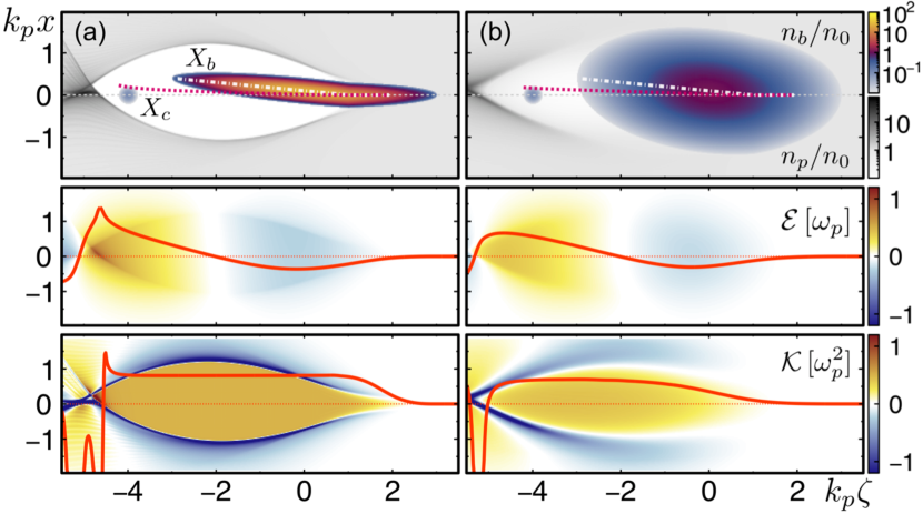
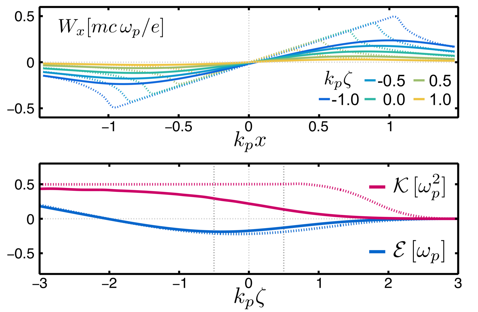
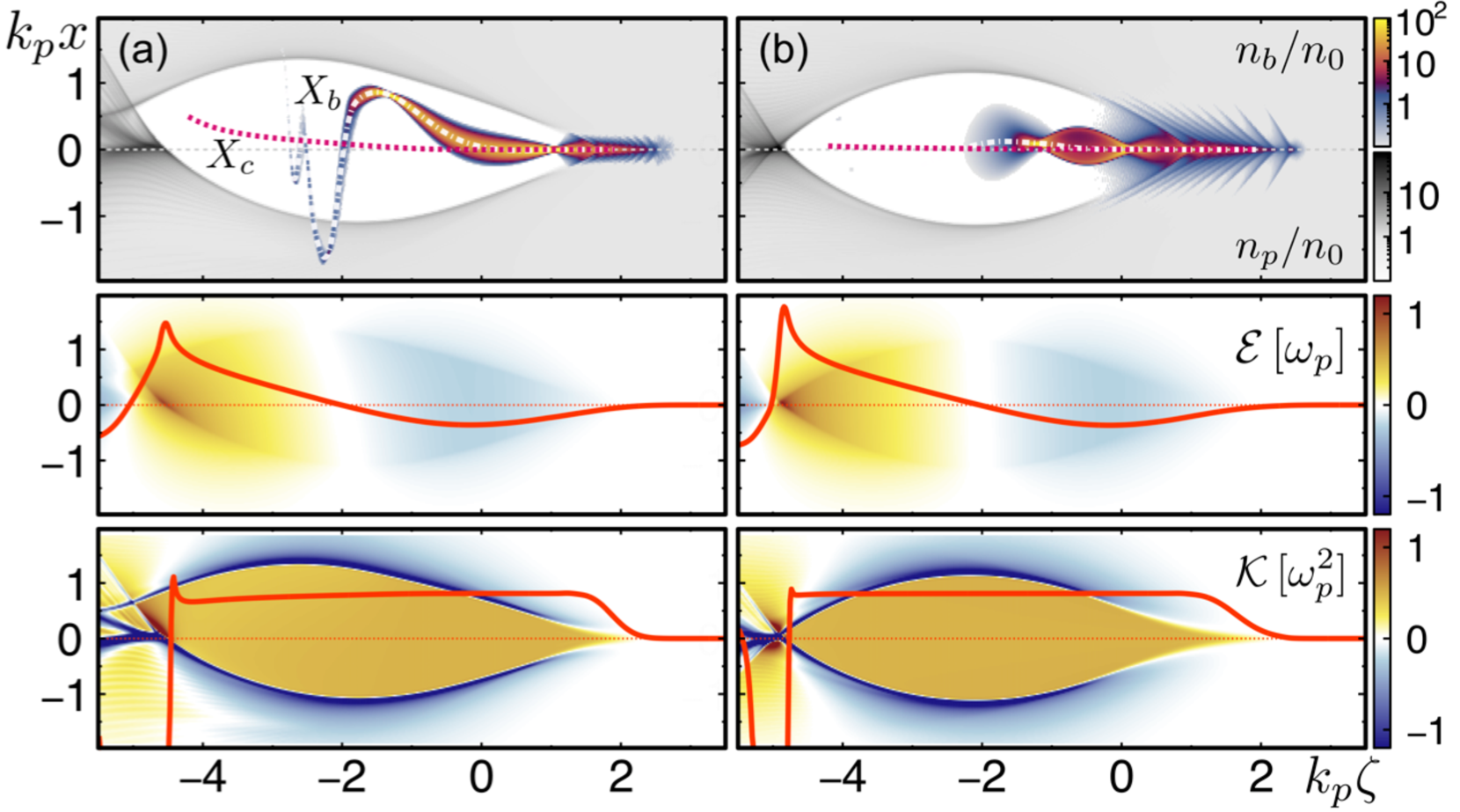
Fig. 1 shows the central plane in the beginning of the propagation in the plasma, for two exemplary simulation runs: Case with and case with . In case , and most of the slices of the drive beam are completely embedded in the blowout cavity (Fig. 1 (a) - top). In case , the beam is wider and initially underdense, and therefore, the blowout formation is only partial in the region of the beam (Fig. 1 (b) - top). The energy change along the beam is similar for both cases (Fig. 1 - middle). The focusing strength along the beam is perfectly uniform for the narrow beam case , but it substantially varies for the wide beam case (Fig. 1 - bottom), where a finite plasma electron density in the region of the beam alters the focusing field associated with the ion channel.
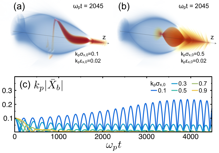
The beam and plasma electron densities at for the cases and are shown in Fig. 2(a) and (b), respectively. After some propagation, the wide drive beam () is transversely compressed by the self-generated focusing field, enhancing in this way the plasma blowout formation (Fig. 2(b)). The average centroid position within a central region of the drive beam with length , is shown as a function of the propagation time in Fig. 2(c), for five different initial values of the transverse size (rms). It is apparent that the average centroid oscillations are rapidly suppressed for the cases with a wide beam. As we explain below, this effect is primarily associated to a quick decoherence between the oscillations of the slices within the central beam region due to a non-uniform focusing strength along the drive beam.
We further investigate the stability of the PWFA in the PIC simulations by studying the evolution of a low-current witness beam, initially placed on the propagation axis at comoving position . The simulations with a narrow drive beam are affected by the HI and the witness beam breaks up after a short propagation distance. Only for the wide drive beam cases with and , where the HI is rapidly suppressed, the witness beams are efficiently accelerated with no slice emittance degradation. Remarkably, the acceleration performance is barely affected, dropping only by and , respectively, when compared to an ideal narrow drive beam case unaffected by hosing. Extended information about the PIC simulation results can be found on the Supplemental Material suppmat .
The decoherence rates owing to longitudinal variations of the betatron frequency can be estimated by considering an infinitesimal -slice with constant and , together with the solutions of Eq. (5). Taking partial derivatives of Eq. (3), we obtain the differential phase advance along the beam
| (6) |
where we have included the contribution from a -dependent initial energy variation in the beam. Eq. (6) is valid up to leading order in , with the energy depletion time. For an early time, , the phase advance difference between different -slices is dominated by either the relative variation of the focusing strength along the beam, , and/or an initial relative energy chirp, which is identically in the hereby considered cases. The differential phase advance caused by the variation of only appears at second order in .
We now consider a beam region with length , an uniform current and with a linear variation of and . The decoherence time for this beam region can be defined by the time at which the head-to-tail difference of the phase advance is on the order of , which correspond to opposite oscillation states. Thus, we use Eq. (6) to estimate the decoherence time when either only , i.e. , or when only , i.e. . The centroid oscillations of various -slices along the beam region are detuned after the respective decoherence times and the impact of the beam region onto the focusing channel deviation, which leads to hosing, is strongly suppressed. As a consequence, the oscillation amplitude of the individual -slices is expected to saturate and the average centroid displacement within the beam region, , to be strongly damped after the decoherence time.
This model is used to evaluate the decoherence of the centroid oscillations within a central beam region with length through the quantity , for two exemplary cases and , that resemble the PIC simulation cases , for a narrow beam with , and , for a wide beam with , respectively. For simplicity, we assume a fixed channel centroid , and , for all the -slices in the cases and . In Fig. 1 we show the values of and for the PIC simulation cases and in the beginning of the propagation in plasma. We adopt the central values and derivatives of these quantities in the analytical calculation of the model cases and . In addition, we perform a numerical integration of the exact equation of motion , for a set of particles representing the considered beam region. This numerical approach allows to account for non-linear effects in the motion of the beam electrons with a higher oscillation amplitude, which otherwise would not be included in a purely analytical calculation. The non-uniformity of and for is also accounted for by adopting the values from the PIC simulations (cf. Fig. 1).
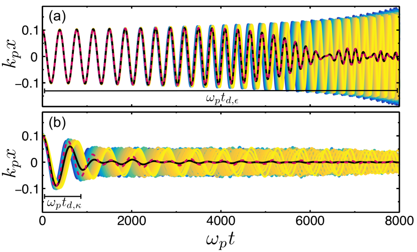
In Fig. 3 we show the centroid oscillations for 50 -slices along the considered beam region (colored curves), together with their average obtained from the numerical approach (black line) and as a result of the analytical model (red dashed line). For case (Fig. 3 (a)), within the considered beam region and the decoherence occurs predominantly from a differential energy change along the beam. In this case, the decoherence time is approximately , which is comparable to the energy depletion time . The analytical model is in excellent agreement with the numerical calculation for this narrow beam scenario. For case (Fig. 3 (b)), and the decoherence from a variation of the focusing strength along the beam region dominates. Hence, the decoherence time can be estimated by , which is on the order of the initial betatron period of the beam electrons . In this case, the model predicts that decoherence is reached on a much shorter time scale than for the narrow beam case , in good qualitative agreement with the behavior observed in the PIC simulation cases and .
We note that for the wide beam case , the non-linear effects on the motion of the electrons with a higher oscillation amplitude cause additional decoherence through intra-slice phase mixing, and consequently, a damping of the centroid oscillation amplitude of the different -slices. As a result, the numerical calculation predicts a slightly higher damping of than the analytical model in case (Fig. 3 (b)). From the comparison between the analytical and the numerical approaches, we identify the decoherence caused by a finite as the main effect responsible for the fast suppression of the HI observed in PIC simulations with wide drive beams.
In conclusion, we show that the HI in PWFAs is rapidly suppressed for drive beams with an initial transverse size comparable to the blowout radius. The intrinsic variation of the focusing strength in the beam region for scenarios with initially wide and underdense drive beams leads to a quick decoherence between the centroid oscillations of various slices along the beam, and consequently, to the suppression of the instability. Still, behind the drive beam the blowout formation is complete and the witness beams are efficiently accelerated with no emittance degradation. This intrinsic stabilization principle provides an applicable and effective method for the suppression of the HI of the drive beam and will allow for a stable acceleration process in future PWFA experiments.
Acknowledgements.
We acknowledge the grant of computing time by the Jülich Supercomputing Center on JUQUEEN under Project No. HHH23 and the use of the High-Performance Cluster (Maxwell) at DESY. T.J.M acknowledges the support by the DAAD with funds from the BMBF and the MSCA of the EU’s FP7 under REA grant no. 605728 (P.R.I.M.E.) and the support by the Director, Office of Science, Office of High Energy Physics, of the U.S. Department of Energy under Contract No. DE-AC02-05CH11231. A.M. acknowledges V. Libov and J. Zemella for useful discussions in the context of start-to-end simulations for FLASHForward, and the Helmholtz Virtual Institute VH-VI-503, for financial support.References
- (1) V. I. Veksler, Conf. Proc. CERN (1956).
- (2) J. B. Rosenzweig, B. Breizman, T. C. Katsouleas, and J. J. Su, Phys. Rev. A44, R6189 (1991).
- (3) E. Oz, S. Deng, T. Katsouleas, P. Muggli, C. D. Barnes, I. Blumenfeld, F. J. Decker, P. Emma, M. J. Hogan, R. Ischebeck, R. H. Iverson, N. Kirby, P. Krejcik, C. O’Connell, R. H. Siemann, D. Walz, D. Auerbach, C. E. Clayton, C. Huang, D. K. Johnson, C. Joshi, W. Lu, K. A. Marsh, W. B. Mori, and M. Zhou, Phys. Rev. Lett. 98, 084801 (2007).
- (4) B. Hidding, G. Pretzler, J. B. Rosenzweig, T. Königstein, D. Schiller, and D. L. Bruhwiler, Phys. Rev. Lett. 108, 035001 (2012).
- (5) A. Martinez de la Ossa, J. Grebenyuk, T. J. Mehrling, L. Schaper, and J. Osterhoff, Phys. Rev. Lett. 111, 245003 (2013).
- (6) A. Martinez de la Ossa, T. J. Mehrling, L. Schaper, M. J. V. Streeter, and J. Osterhoff, Phys. Plasmas 22, 093107 (2015).
- (7) G. Wittig, O. Karger, A. Knetsch, Y. Xi, A. Deng, J. B. Rosenzweig, D. L. Bruhwiler, J. Smith, G. G. Manahan, Z.-M. Sheng, D. A. Jaroszynski, and B. Hidding, Phys. Rev. ST Accel. Beams 18, 081304 (2015).
- (8) A. Martinez de la Ossa, Z. Hu, M. J. V. Streeter, T. J. Mehrling, O. Kononenko, B. Sheeran, and J. Osterhoff, Phys. Rev. Accel. Beams 20, 091301 (2017).
- (9) K. V. Lotov, Phys. Plasmas 12, 053105 (2005).
- (10) M. Tzoufras, W. Lu, F. S. Tsung, C. Huang, W. B. Mori, T. Katsouleas, J. Vieira, R. A. Fonseca, and L. O. Silva, Phys. Rev. Lett. 101, 145002 (2008)
- (11) C. Huang, W. Lu, M. Zhou, C. E. Clayton, C. Joshi, W. B. Mori, P. Muggli, S. Deng, E. Oz, T. Katsouleas, M. J. Hogan, I. Blumenfeld, F. J. Decker, R. Ischebeck, R. H. Iverson, N. A. Kirby, and D. Walz, Phys. Rev. Lett. 99, 255001 (2007).
- (12) T. J. Mehrling, R. A. Fonseca, A. Martinez de la Ossa, and J. Vieira, Phys. Rev. Lett. 118, 174801 (2017).
- (13) T. J. Mehrling, C. Benedetti, C. B. Schroeder, and J. Osterhoff, Plasma Phys. Control. Fusion 56, 084012 (2014).
- (14) V. E. Balakin, A. V. Novokhatsky, and V. P. Smirnov, Conf. Proc. C830811 (1983).
- (15) G. Stupakov, SLAC-AP 108 (1997).
- (16) C. L. Bohn and K.-Y. Ng, Phys. Rev. Lett. 85, 984 (2000).
- (17) J. Vieira, W. B. Mori, and P. Muggli, Phys. Rev. Lett. 112, 205001 (2014).
- (18) R. Lehe, C. B. Schroeder, J.-L. Vay, E. Esarey, and W. P. Leemans, Phys. Rev. Lett. 119, 244801 (2017).
- (19) M. J. Hogan, T. O. Raubenheimer, A. Seryi, P. Muggli, T. Katsouleas, C. Huang, W. Lu, W. An, K. A. Marsh, W. B. Mori, C. E. Clayton, and C. Joshi, New J. Phys. 12, 055030 (2010).
- (20) A. Aschikhin, C. Behrens, S. Bohlen, J. Dale, N. Delbos, L. di Lucchio, E. Elsen, J.-H. Erbe, M. Felber, B. Foster, L. Goldberg, J. Grebenyuk, J.-N. Gruse, B. Hidding, Z. Hu, S. Karstensen, A. Knetsch, O. Kononenko, V. Libov, K. Ludwig, A. Maier, A. Martinez de la Ossa, T. Mehrling, C. Palmer, F. Pannek, L. Schaper, H. Schlarb, B. Schmidt, S. Schreiber, J.-P. Schwinkendorf, H. Steel, M. Streeter, G. Tauscher, V. Wacker, S. Weichert, S. Wunderlich, J. Zemella, and J. Osterhoff, Nucl. Instrum. Methods Phys. Res. A 806, 175 (2016).
- (21) V. Yakimenko, Y. Cai, C. Clarke, S. Green, C. Hast, M.J. Hogan, N. Lipkowitz, N. Phinney, G. White and G. Yocky, Proc. IPAC (2016).
- (22) T. Heinemann, R. W. Assmann, J. P. Couperus, B. Hidding, A. Knetsch, O. Kononenko, A. Köhler, T. Kurz, U. Schramm, O. Zarini, A. Irman, and A. Martinez de la Ossa, Proc. IPAC (2017).
- (23) P. Chen, Part. Accel. 20, 171 (1987).
- (24) R. Keinigs and M. E. Jones, Phys. Fluids 30, 252 (1987).
- (25) K. V. Lotov, Phys. Rev. E69, 046405 (2004).
- (26) W. Lu, C. Huang, M. Zhou, W. B. Mori, and T. Katsouleas, Phys. Rev. Lett. 96, 165002 (2006).
- (27) I. Kostyukov, A. Pukhov, and S. Kiselev, Phys. Plasmas 11, 5256 (2004).
- (28) D. H. Whittum, W. M. Sharp, S. S. Yu, M. Lampe, and G. Joyce, Phys. Rev. Lett. 67, 991 (1991).
- (29) M. Lampe, G. Joyce, S. P. Slinker, and D. H. Whittum, Phys. Fluids B 5, 1888 (1993).
- (30) See Supplemental Material for a description of numerical and physical parameters, and additional information about the PIC simulations results.
Supplemental material: Simulation Setup and Extended Results
A. Martinez de la Ossa,1,∗ T.J. Mehrling,2,3 and J. Osterhoff2
1Institut für Experimentalphysik, Universität Hamburg, 22761 Hamburg, Germany
2Deutsches Elektronen-Synchrotron DESY, 22607 Hamburg, Germany
3Lawrence Berkeley National Laboratory, Berkeley, California 94720, USA
∗alberto.martinez.de.la.ossa@desy.de
(Dated: March 15, 2024)
.1 Simulation Setup
For the PIC simulations, the quasi-static code HiPACE Mehrling2014-S is used together with the following physical setup. We consider perfectly monoenergetic, highly relativistic drive beams with and with the following electron density profile:
| (S1) |
where , with , the peak current of the beam and , the Alfvèn current. The beam-centroid is initially linearly tilted in the direction, starting at , such that for and otherwise. The spatial tilt in the direction provides a well defined seed to the hosing instability. The initial transverse phase-space distribution of the beams is Gaussian in both and . The initial transverse (rms) size of the beam, , is varied in the simulations from to , in combination with its initial emittance, , which ranges from to . Initially, the beams are at waist, i.e . In addition, a short, , narrow, and perfectly mono-chromatic low-current witness beam is added to the simulations, in order to test the acceleration performance. The considered witness beam has the same initial energy and emittance as the drive beam and it is initially placed on the propagation axis at comoving position . The simulations use a moving window propagating at . The dimensions of the simulation box are . The simulation box is divided into cells, which gives cell sizes of and . Each cell contains simulation particles for the beam electrons and particles for the plasma electrons. The time step for the calculation of the electromagnetic fields is , which is much smaller that the inverse of the maximum betatron frequency of the beam electrons .
.2 Extended Results
In this section we present a series of figures showing extended information from PIC simulations. In addition to Fig. 1, which shows the central plane in the beginning of the propagation in the plasma, for two exemplary simulation runs: Case with and case with , both with , we have added here Fig. S1, which shows the transverse lineouts of the focusing field for five comoving positions along the drive beam (top panel), and the longitudinal lineouts of and along the propagation axis (bottom panel). The energy change along the beam is similar for both cases. The focusing strength along the beam is perfectly uniform for the narrow beam case , but it substantially varies for the wide beam case .
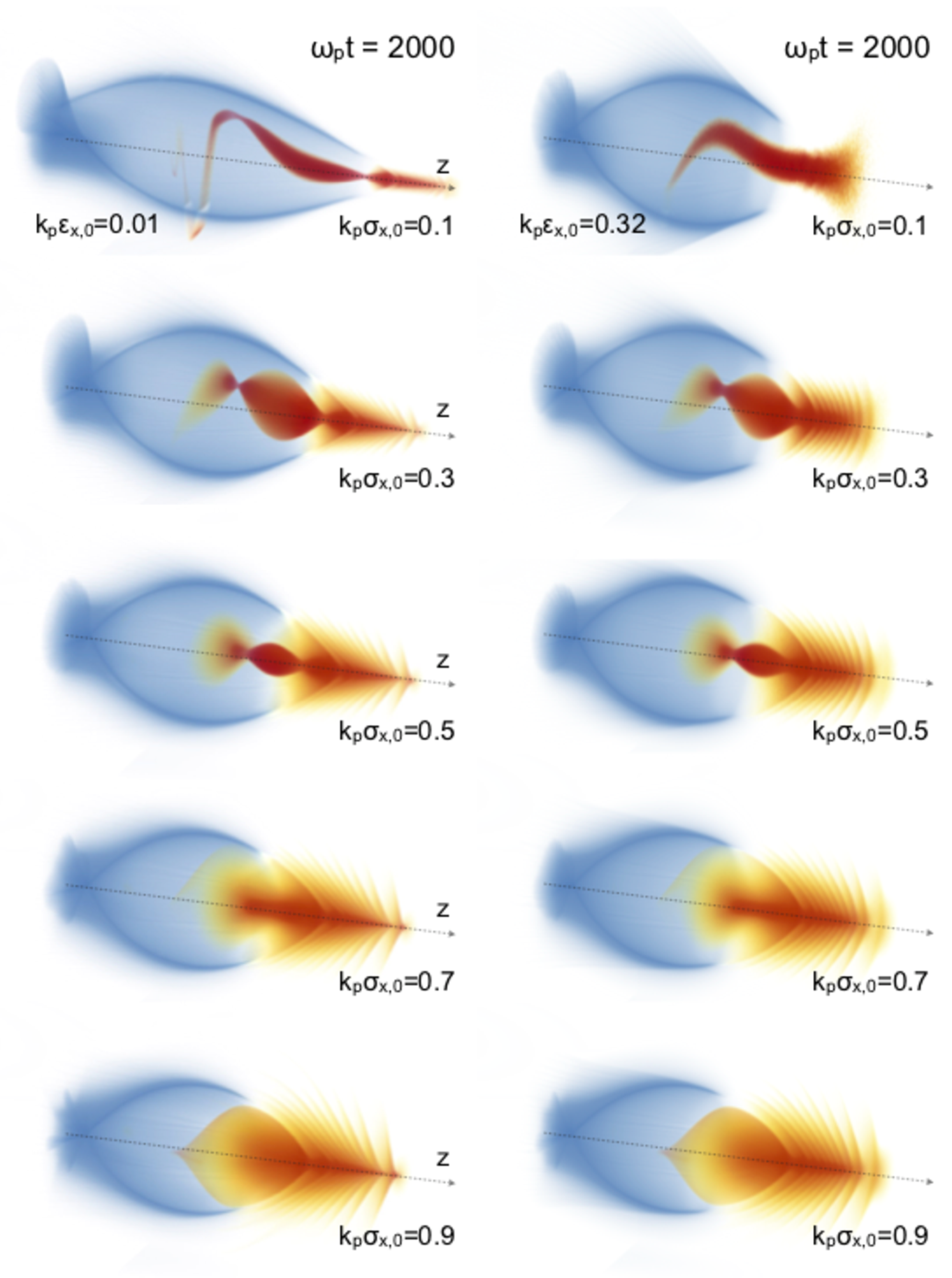
Fig. S2 shows the central plane after a propagation time , for the same exemplary simulation runs and . It is apparent that, due to the self-generated focusing field, the wide drive beam is transversely focused, and therefore, the blowout formation is enhanced. Fig. S3 shows the beam and plasma densities after a propagation time for five simulation cases with (left column) and five simulation cases with (right column). The initial transverse size (rms) of the drive beam is increased from top to bottom, ranging from to in steps of . Here we see again that the blowout formation behind the driver is complete, also for the initially wide drive beams, barely differing from the narrow cases.
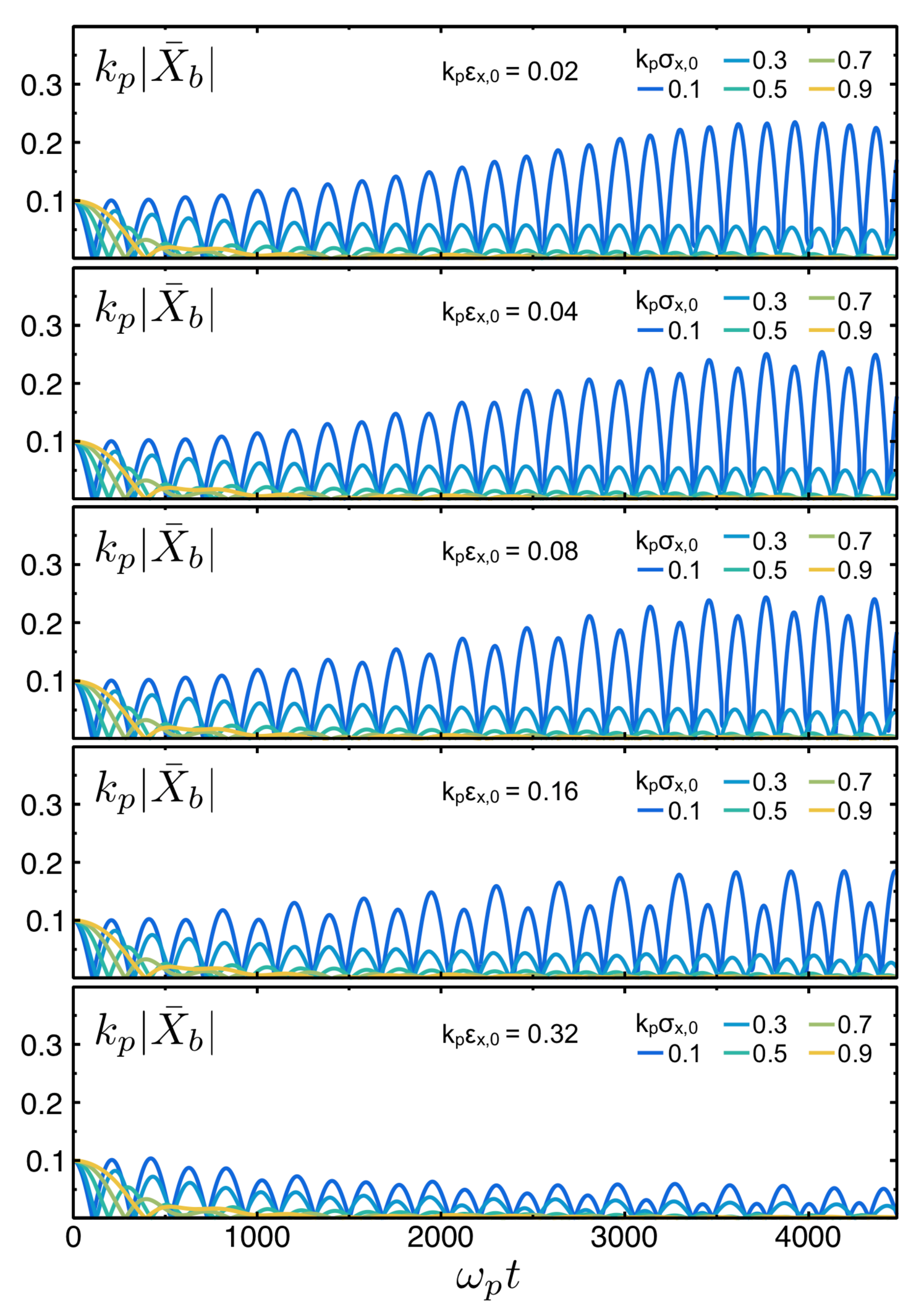
Fig. S4 shows the average centroid oscillations of the central region of the drive beam when its initial emittance is increased with respect to the narrow case considered in the article, i.e. with . For the wide drive beam cases with , the average transverse oscillations of the beam are strongly damped after a short propagation time, for any of the considered values of the initial emittance. The effect of a higher initial emittance is only relevant for the narrow drive beam cases. We observe that, for the narrow beam case with and , the head of the beam expands transversely (cf. Fig. S3 upper-right corner) and, after few betatron oscillations, the central beam region is affected by the decoherence associated to a non-uniform , causing the damping of the average centroid oscillations.
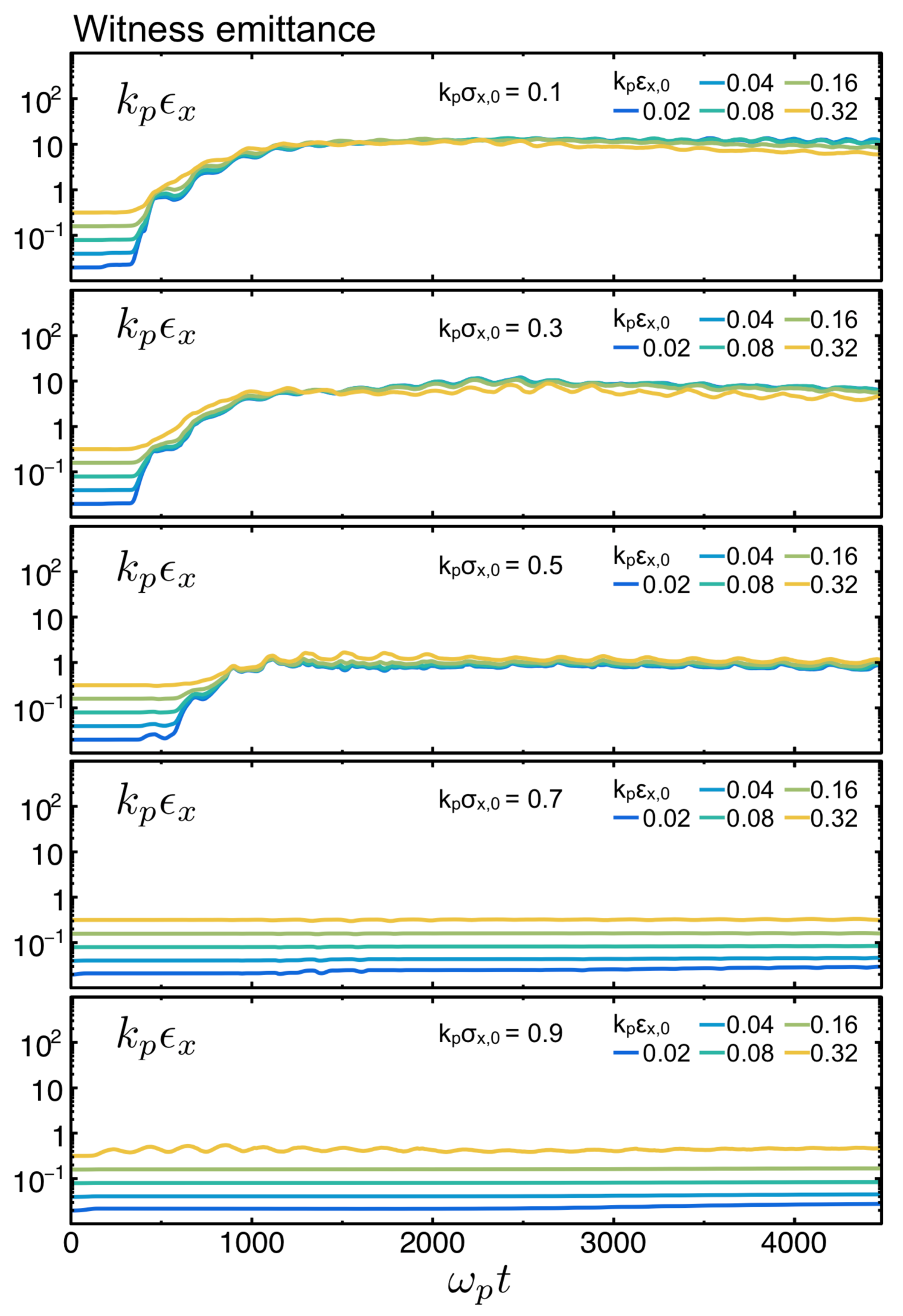
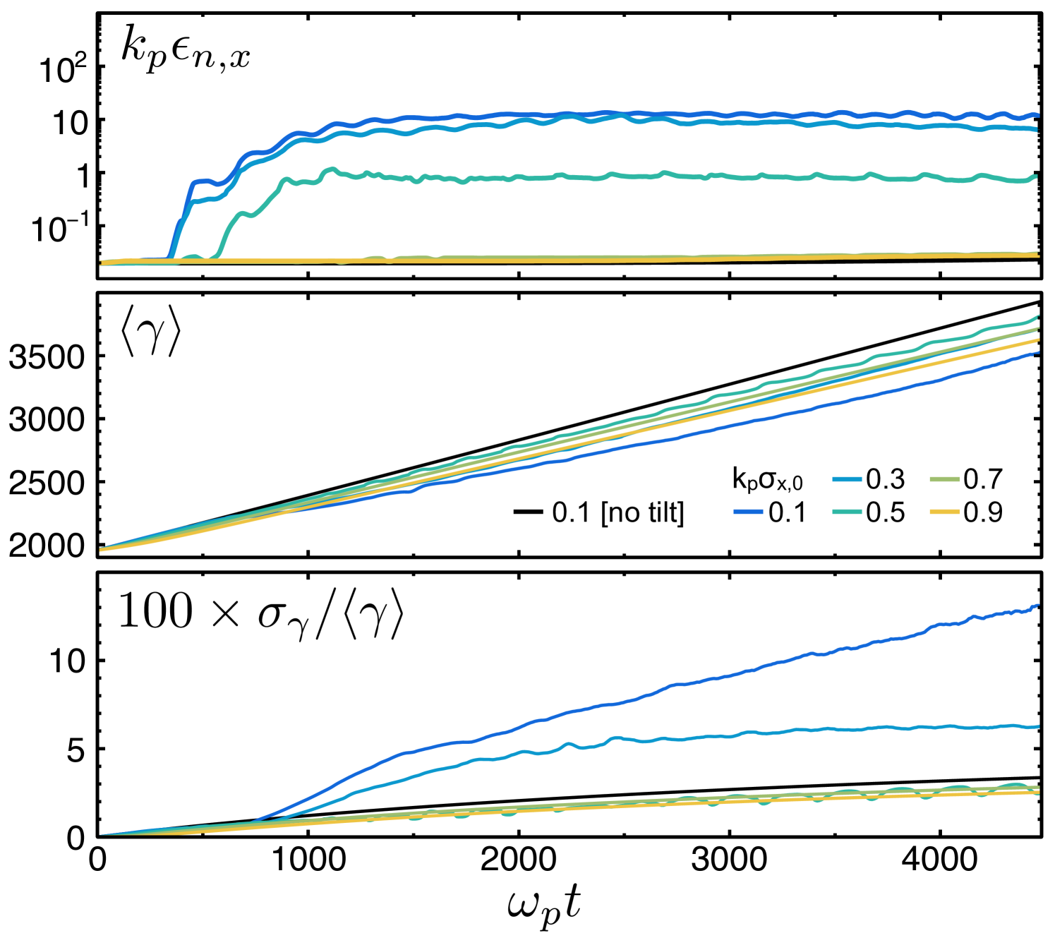
Fig. S5 shows the average slice emittance of the witness beam as a function of the propagation time, for five PIC simulation cases with different initial emittance and same initial transverse size of the drive beam, which ranges from to (from top to bottom). Fig. S6 shows the time evolution of the average sliced emittance (top panel), the average energy (middle panel) and the relative energy spread (bottom panel) of the witness beam, for five cases with increasing initial drive beam size. Only for the initially wide beam cases with and , the hosing instability could be rapidly suppressed and the witness beams could be efficiently accelerated with no emittance growth. The acceleration performance in terms of the achieved energy gain in the witness beam is less for the case with and less for the case with , with respect to a reference case with and no initial tilt (i.e. no hosing seed). The relative energy spread of the witness beam after a propagation time is for the case with , for the case with and for the reference case with and no initial tilt.
We have also included in the Supplemental Material online two PIC simulation movies showing the beam and electron densities as a function of the propagation time, for two exemplary cases with a narrow beam (case ) and a wide beam (case ).
References
- (1) T. J. Mehrling, C. Benedetti, C. B. Schroeder, and J. Osterhoff, Plasma Phys. Control. Fusion 56, 084012 (2014).