Charged particle timing at sub-25 picosecond precision: the PICOSEC detection concept
Abstract
The PICOSEC detection concept consists in a “two-stage” Micromegas detector coupled to a Cherenkov radiator and equipped with a photocathode. A proof of concept has already been tested: a single-photoelectron response of 76 ps has been measured with a femtosecond UV laser at CEA/IRAMIS, while a time resolution of 24 ps with a mean yield of 10.4 photoelectrons has been measured for 150 GeV muons at the CERN SPS H4 secondary line. This work will present the main results of this prototype and the performance of the different detector configurations tested in 2016-18 beam campaigns: readouts (bulk, resistive, multipad) and photocathodes (metallic+CsI, pure metallic, diamond). Finally, the prospects for building a demonstrator based on PICOSEC detection concept for future experiments will be discussed. In particular, the scaling strategies for a large area coverage with a multichannel readout plane, the R&D on solid converters for building a robust photocathode and the different resistive configurations for a robust readout.
keywords:
picosecond timing, MPGD, Micromegas, photocathodes, timing algorithmsFast timing is a key feature for particle identification through particle mass measurement at high-energy colliders and in nuclear physics facilities. More specifically, tens of picoseconds in precision timing are needed for the High Luminosity upgrade of LHC (HL-LHC) in order to mitigate the foreseen pile-up background of ATLAS/CMS experiments, which could reach in some cases 150-200 vertices [1]. Various types of detectors are being developed to reach such precision [2]. In solid-state field, Silicon photomultipliers (SiPMs) [3], Low Gain Avalanche Detectors (LGAD) [4], Micro-Channel Plate Photo-Multiplier (MCP-PMT) [5] or Ultra Fast Silicon Detectors (UFSD) [6] are some examples. In gaseous detectors, the PICOSEC detection concept, based on Micro-Pattern Gaseous Detectors (MPGD), has recently reached a sub-25 picosecond timing precision for Minimum Ionization Particles (MIP) of 150 GeV muons [7]. This manuscript reviews the main results of the first PICOSEC prototype and the scaling strategies to build a demonstrator for a future experiment or upgrade.
1 Detection concept
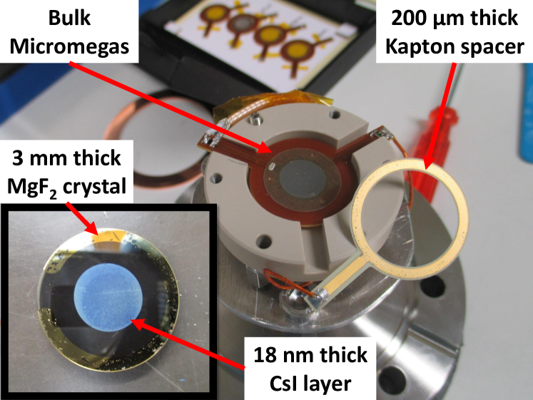
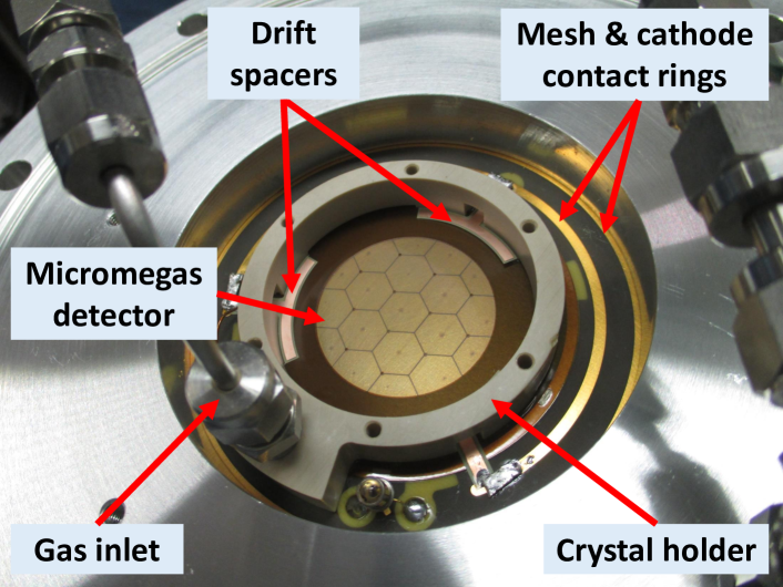
The PICOSEC detector concept [7] consists of a two-stage amplification Micromegas detector coupled to a Cherenkov radiator coated with a photocathode, as shown in Fig. 1. A charged particle crossing the radiator produces Cherenkov light in the extreme Ultra Violet (UV) wavelength (below 200 nm), which is simultaneously converted into electrons at the photocathode (a 18 nm CsI layer in the first prototype). The photocathode is deposited on a metallic layer, typically a 5.5 nm-thick chromium layer, which works as cathode of the first stage of the Micromegas (called drift gap in literature). The primary photo-electrons are preamplified in this stage, partially traverse the Micromegas mesh and are finally amplified in the second stage (called amplification gap). In the first prototype (Fig. 2), the drift gap is 200 µm thick and is defined by circular kapton spacers, while the amplification gap is 128 µm thick and is defined by only 6 pillars. The two gaps are filled with COMPASS gas (80%Ne + 10%C2H6 + 10%CF4) at 1 bar absolute pressure.
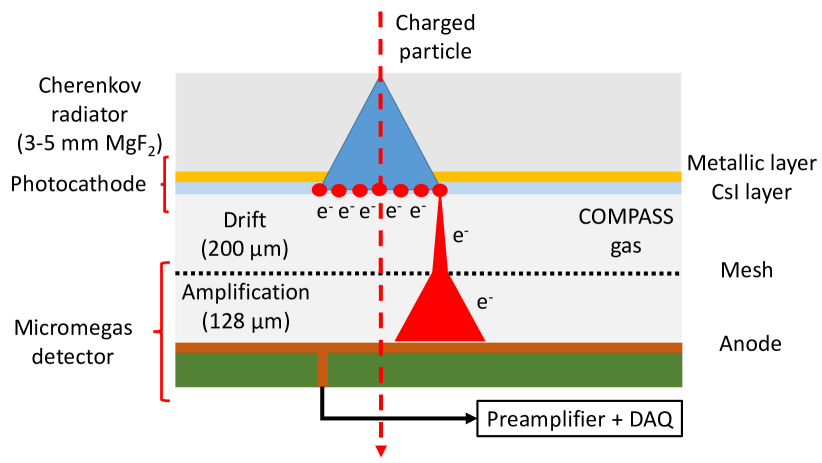
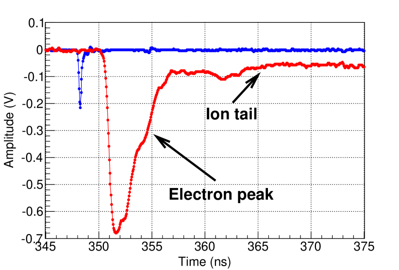
The arrival of the amplified electrons at the Micromegas anode generates a fast signal (with a risetime of 0.5 ns) referred to as the electron-peak, while the movement of the ions, produced in the amplification gap, to the mesh generates a slower component - ion-tail (100 ns). An example of the induced signal by a 150 GeV muon is illustrated in Fig. 3.
2 Timing results
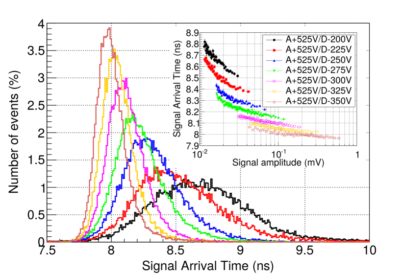
The time response of the first PICOSEC prototype has been measured for single photoelectrons with the help of a femtolaser of the CEA/IRAMIS laboratory. In our setup, the laser beam is split into two equal parts, one arrives directly at the prototype and the other at a fast photodiode, with a time resolution of 13 ps. The intensity of the laser arriving at the detector is reduced by light attenuators, so that the charge distribution is compatible with single photoelectron. The PICOSEC detector signal is preamplified by a CIVIDEC module (2 GHz, 40 dB) before being digitized and registered together with the photodiode signal by a 2.5 GHz oscilloscope at a rate of 20 GSamples/s (i.e. one sample every 50 ps). The temporal distance between the two signals (called Signal Arrival Time or SAT) is calculated by a Constant Fraction method. An example of the resulting SAT distributions is shown in Fig. 5 for a fixed anode voltage. This figure illustrates: 1) the improvement in timing with the drift field; and 2) the correlation between the SAT and the signal amplitude, which causes a tail at high SAT values. These observations do not have an electronic origin, as the signal shape is the same for different signal sizes, but can be explained by the charge amplification in the first Micromegas detector stage, as shown in a detailed detector response simulation [8]. The detector time resolution at each operation point has been derived from the SAT-amplitude correlations, leading to a best value of 76.0 0.4 ps [7].
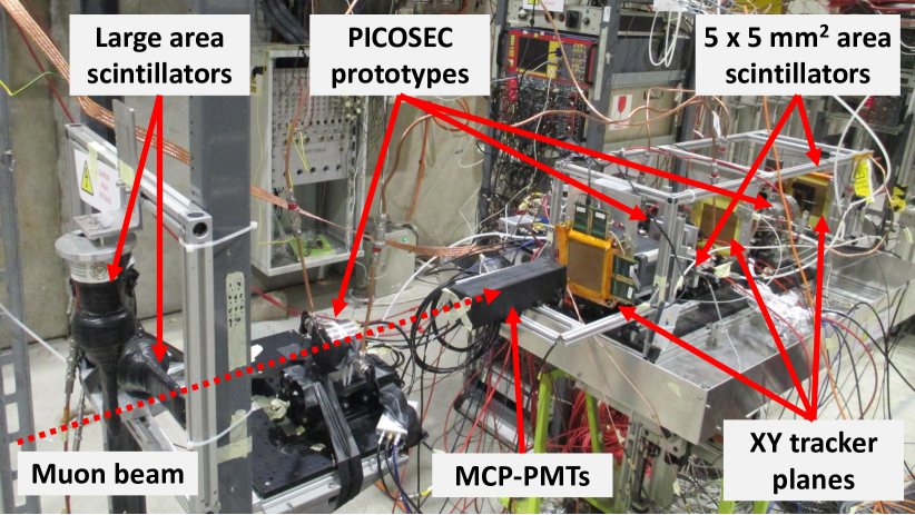
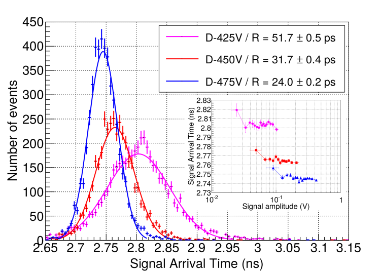
The time response of the PICOSEC detector to 150 GeV muons has been measured in several beam tests in 2016-18 at the CERN SPS H4 secondary beamline. The beam telescope (Fig. 4) consists of a tracking system composed of three triple-Gas Electron Multipliers (GEMs) and with a spatial resolution better than 40 µm; one MCP-PMT [5] as time reference with a time resolution better than 5 ps [9]; different scintillators to select tracks and to veto showers; and up to five prototypes. As in the laser setup, the PICOSEC signal is preamplified and registered together with the MCP-PMT signal, as well as one digitized event number from the tracking system. An example of the SAT distributions of the first PICOSEC prototype is shown in Fig. 6. This figures illustrates: 1) the improvement in timing with the drift field; 2) the absence of correlation between the SAT and the amplitude, due to high drift voltages; and 3) a best value for time resolution of 24.0 0.2 ps, as reported in [7]. The mean number of photoelectrons per muon was also calculated comparing the electron-peak charge distribution by the one generated by single photoelectrons (measured by a UV-lamp calibration), giving a value of 10.4 0.4.
3 On going R&D for a demonstrator
Several components of the first PICOSEC prototype must gain in robustness and scalability before a demonstrator could be proposed to an experiment. This is the aim of several on going R&Ds, briefly discussed in this section:
-
1.
Resistive Micromegas detectors [10] do not show any degradation of the signal efficiency and the spatial resolution in pion beams with respect to non resistive detectors [11]. Two configurations have been already tested: the resistive strip one [12] and the floating strip one [13]. In both cases, the best value for time resolutions is 28-40 ps, slightly worse than the reference value, but with a proven operation and stability in 150 GeV pion beam over hours.
-
2.
The Multipad detector (Fig. 7) is the first prototype to test the scalability of PICOSEC detection concept. It has a 36 mm diameter active area divided in 19 hexagonal anode pads. The 19 anode pads, the mesh and cathode electrodes are routed to the back side of the Printed Circuit Board (PCB), where they are connected to the electronics. A woven stainless-steel mesh is laminated on the PCB to make a bulk detector (128 µm thick amplification gap). The 200 µm thick drift gap is defined by ring spacers and the 2 inches diameter crystal is held by a PEEK structure.
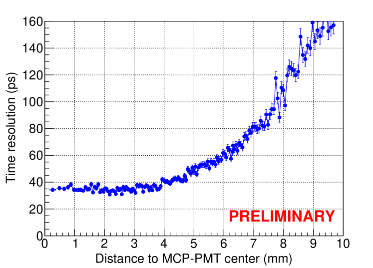
The detector was tested in October 2017 beam tests in two configurations: in the first one, the MCP-PMT, the central pad and a 5 5 mm2 scintillator were aligned to study the timing of a single pad for different voltage configurations; in the second one, the MCP-PMT center was situated at the intersection of three pads, the pads were covered by a 4 5 cm2 scintillator area and events were acquired at the optimum operation point in order to combine the timing of the three pads. In both cases, preliminary results show a time resolution of 36 ps. The result of the second case is limited by the MCP optimum performance area (Fig. 8), which extends up to a radius of 5.5 mm [9].
-
3.
CsI shows a high quantum efficiency as a photocathode (of more than 25% at 180 nm wavelength [14]) but is hydrophobic and less resistant to ion-backflow [15]. Different alternatives are being explored: pure metallic photocathodes, diamond-based photocathodes or protection layers for the CsI. Preliminary results have shown a time resolution of 60 ps for the first two types (5 mm thick MgF2 + 10 nm Al and 3 mm thick MgF2 + 20 nm Diamond Like Carbon), and 2 photoelectrons per muon.
-
4.
The commercial preamplifier will be replaced by on-board electronics with spark protection in a new prototype; while the substitution of oscilloscope as DAQ with ultra-fast digitizers like SAMPIC [16] is also being studied.
4 Conclusions
The PICOSEC detection concept, composed of a two-stage Micromegas detector coupled to a Cherenkov radiator and equipped with a photocathode, has been presented. The first prototype has shown a timing resolution of about 76 ps for single photoelectrons and about 24 ps for 150 GeV muons. To improve the robustness and scalability of different components, a R&D program has been launched. First results with resistive Micromegas, in multipad configuration and with different photocathodes are promising.
Acknowledgments
We acknowledge the financial support of the RD51 collaboration, in the framework of RD51 common projects, the Cross-Disciplinary Program on Instrumentation and Detection of CEA, the French Alternative Energies and Atomic Energy Commission; and the Fundamental Research Funds for the Central Universities of China. We also thank K. Kordas for valuable suggestions concerning the analysis of the data. J. Bortfeldt acknowledges the support from the COFUND-FP-CERN-2014 program (grant number 665779). M. Gallinaro acknowledges the support from the Fundação para a Ciência e a Tecnologia (FCT), Portugal (grants IF/00410/2012 and CERN/FIS-PAR/0006/2017). D. González-Díaz acknowledges the support from MINECO (Spain) under the Ramon y Cajal program (contract RYC-2015-18820). F.J. Iguaz acknowledges the support from the Enhanced Eurotalents program (PCOFUND-GA-2013-600382). S. White acknowledges partial support through the US CMS program under DOE contract No. DE-AC02-07CH11359.
References
- [1] S. White, “Experimental Challenges of the European Strategy for Particle Physics”, in Proceedings, International Conference on Calorimetry for the High Energy Frontier (CHEF 2013): Paris, France, April 22-25, 2013, pp. 118–127, 2013. 1309.7985.
- [2] J. Vavra, PID techniques: Alternatives to RICH methods, Nucl. Instrum. Meth. A876 (2017) 185–193.
- [3] S. Gundacker et al., SiPM time resolution: From single photon to saturation, Nucl. Instrum. Meth. A718 (2013) 569–572.
- [4] G. Pellegrini et al., Technology developments and first measurements of Low Gain Avalanche Detectors (LGAD) for high energy physics applications, Nucl. Instrum. Meth. A765 (2014) 12–16.
- [5] A. Ronzhin, S. Los, E. Ramberg, A. Apresyan, S. Xie, M. Spiropulu et al., Study of the timing performance of micro-channel plate photomultiplier for use as an active layer in a shower maximum detector, Nucl. Instrum. Meth. A795 (2015) 288–292.
- [6] N. Cartiglia et al., Design optimization of ultra-fast silicon detectors, Nucl. Instrum. Meth. A796 (2015) 141–148.
- [7] J. Bortfeldt et al., PICOSEC: Charged particle timing at sub-25 picosecond precision with a Micromegas based detector, accepted in Nucl. Instrum. Meth. A (2018) .
- [8] K. Paraschou and S. Tzamarias, “A data driven simulation study of the timing effects observed with the picosec micromegas detector.” https://indico.cern.ch/event/676702/contributions/2809871/attachments/1574857/2486512/Konstantinos_RD51_miniweek.pdf, Dec. 13, 2017.
- [9] L. Sohl, Spatial time resolution of MCP–PMTs as a t0-reference, submitted to Nucl. Instrum. Meth. A (2018) .
- [10] J. Wotschack, The development of large-area Micromegas detectors for the ATLAS upgrade, Mod. Phys. Lett. A28 (2013) 1340020.
- [11] MAMMA collaboration, J. Manjarres et al., Performances of Anode-resistive Micromegas for HL-LHC, JINST 7 (2012) C03040.
- [12] T. Alexopoulos et al., A spark-resistant bulk-micromegas chamber for high-rate applications, Nucl. Instrum. Meth. A640 (2011) 110–118.
- [13] J. Bortfeldt, The Floating Strip Micromegas Detector. Springer, 2015, 10.1007/978-3-319-18893-5.
- [14] C. Lu and K. McDonald, Properties of reflective and semitransparent csi photocathodes, Nucl. Instrum. Meth. A343 (1994) 135–151.
- [15] A. Breskin, CsI UV photocathodes: History and mystery, Nucl. Instrum. Meth. A371 (1996) 116–136.
- [16] E. Delagnes, D. Breton, H. Grabas, J. Maalmi and P. Rusquart, Reaching a few picosecond timing precision with the 16-channel digitizer and timestamper SAMPIC ASIC, Nucl. Instrum. Meth. A787 (2015) 245–249.