A Wedge Test in MICE††thanks: MICE has been made possible by grants from DOE, NSF (U.S.A), the INFN (Italy), the STFC (U.K.), the European Community under the European Commission Framework Programme 7, the Japan Society for the Promotion of Science, the Swiss National Science Foundation, and the Fermi Research Alliance, LLC operating Fermilab under contract No. DE-AC02-07CH11359 with the U.S. Department of Energy.
Abstract
Emittance exchange mediated by wedge absorbers can be used for longitudinal ionization cooling and for final transverse emittance minimization for a muon collider. A wedge absorber within the Muon Ionization Cooling Experiment (MICE) could serve as a demonstration of the type of emittance exchange needed for six-dimensional (6D) cooling, including the configurations needed for muon colliders. Parameters for this test have been explored in simulation and applied to experimental configurations using a wedge-shaped absorber. A polyethylene wedge absorber has been fabricated and placed in MICE and data has been collected for both direct emittance exchange, where the longitudinal emittance decreases, and reverse emittance exchange, where the transverse emittance decreases. The simulation studies that led to the magnet and beam configurations are presented.
1 Muon Ionization Cooling Experiment
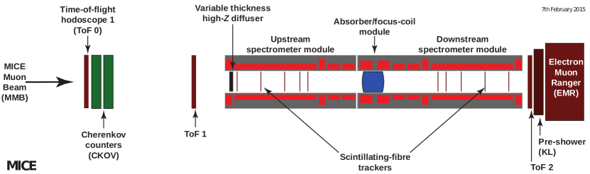
The Muon Ionization Cooling Experiment (MICE) is the first experiment to demonstrate muon ionization cooling, the only beam cooling technique capable of reducing the muon beam phase space volume within its short lifetime [1]. The process of ionization cooling involves the passage of muons through material where the phase-space volume or emittance of the muon beam is reduced through ionization energy loss of muons in material. MICE (Fig. 1) consists of two scintillating-fiber tracking detectors, one upstream and one downstream of the absorber [2]. Each tracker comprises five scintillating-fiber stations each with three doublet fiber layers. The muon beam cooling which results from ionization energy loss of muons in absorber is measured and compared at the locations of the tracker stations closest to the location of the absorber (referred to as tracker reference planes). The Spectrometer Solenoids housing the trackers are each made of five superconducting coils, with two used for beam matching at the absorber and three for maintaining constant solenoidal fields in the tracking volumes.
2 Emittance Exchange Concept
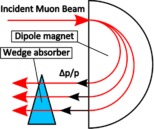
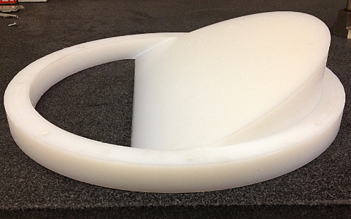
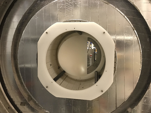
Due to the energy straggling effect in the energy loss, the use of a flat absorber in MICE can only lead to transverse phase-space volume reduction. Emittance exchange can be demonstrated in MICE by passing a dispersive beam through a wedge absorber to cause higher energy muons to pass through more material and lose more energy [1, 3, 6, 4, 5, 7]. This method causes the longitudinal emittance to be reduced, enabling longitudinal cooling at the expense of transverse emittance increase (see Fig. 2). A polyethylene wedge absorber has been fabricated (see Fig. 3) and installed in the MICE cooling channel (see Fig. 4). Data has been collected with wedge, and 14 million particle triggers have been recorded.
3 Simulation Process
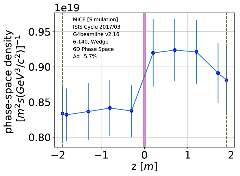
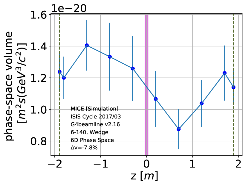
The G4beamline [8] simulation package is used for tracking of muons in the MICE cooling channel as they traverse a wedge absorber. In order to preserve the desired beam dispersion in the MICE beam, an initial particle distribution is generated at the absorber and then propagated backwards to the center of the upstream tracker. The beam input emittance is mm and the reference momentum is MeV/. The beam consists of muons that are tracked using G4beamline across the wedge. The currents in the Spectrometer Solenoids and the absorber focus coils are one of the magnet configurations with which the wedge data was collected (with one downstream matching coil turned off). The transmission loss is % and no transmission cut is applied to discard the muons that scrape downstream of the wedge. In this simulation study, the increase in phase-space density and reduction in phase-space volume are measured as figures of merit for beam cooling. The kernel density estimation (KDE) technique, as a powerful non-parametric density estimator in muon beam cooling [9, 10, 11, 12, 13], has been applied to the simulated beam output in order to estimate the phase-space density and volume of the muon beam and identify the beam core in the four (transverse phase space), six (full transverse and longitudinal phase space), and two (longitudinal phase space) dimensional phase space. The core contour density and volume are then tracked from upstream to downstream tracker reference plane, passing through the wedge where the exchange of the longitudinal and transverse phase space is observed.
4 Results
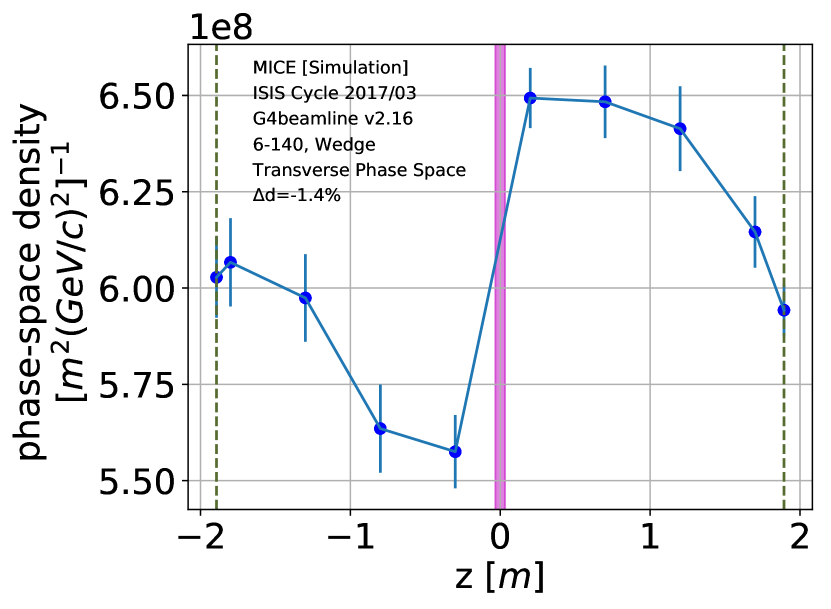
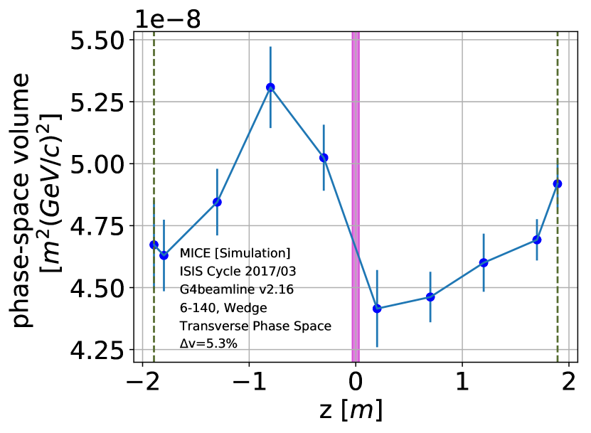
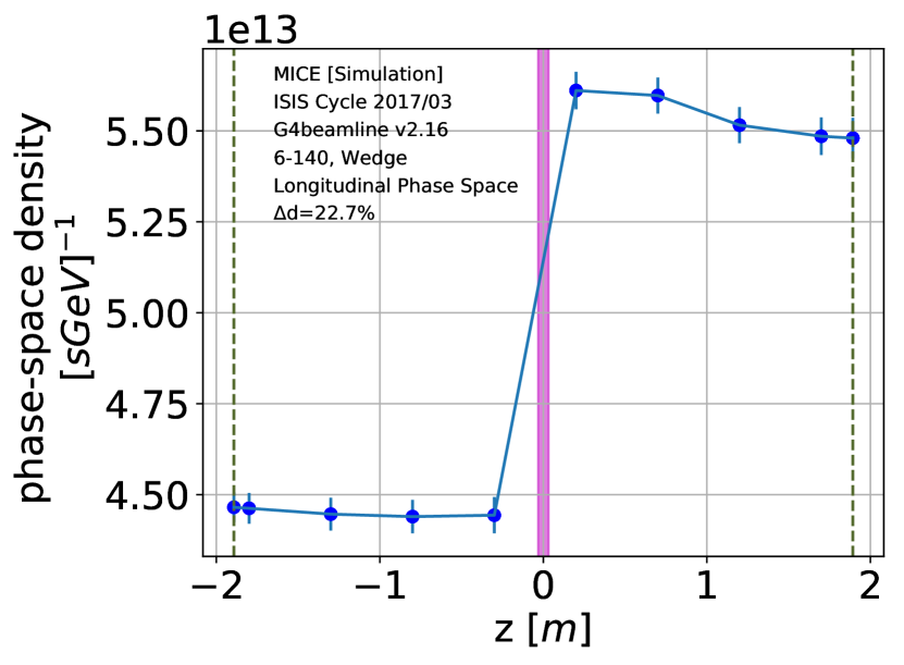
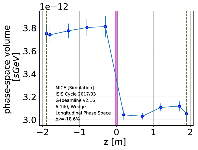
The six-dimensional phase-space evolution plots are shown in Figs. 5 and 6. The core of the beam in 6D corresponds to the -percentile contour. Density increases and volume decreases when the beam passes through the wedge absorber. The transverse phase-space evolution plots are shown in Figs. 7 and 8 where the evolutions of transverse density and volume of the core contour (-percentile contour in 4D) are plotted. There is a reduction in phase-space density and an increase in phase-space volume, indicating heating in the transverse direction. This heating effect combined with the longitudinal cooling seen in Figs. 9 and 10 are a demonstration of the transverse-longitudinal phase-space exchange.
5 conclusion
The emittance exchange has been demonstrated in simulation using the kernel density estimation (KDE) technique. The application of the KDE technique to wedge data is in progress. MICE wedge data has a small natural dispersion and algorithms are being developed that can re-weight the beam distribution.
6 Acknowledgement
The first author acknowledges the support that she has received from United States National Science Foundation, the Division of Physics of Beams of the American Physical Society, and TRIUMF to attend IPAC 2018.
References
-
[1]
D. Neuffer, “Principles and applications of muon cooling,” Part. Accel., vol. 14, pp. 75–90, FERMILAB-FN-0378 (1983).
D. Stratakis et al., “Tapered channel for six-dimensional muon cooling towards micron-scale emittances,” Phys. Rev. ST Accel. Beams 16, 091001 (2013).
D. Stratakis and R. Palmer, “Rectilinear six-dimensional ionization cooling channel for a muon collider: A theoretical and numerical study,” Phys. Rev. ST Accel. Beams 18, 031003 (2015). - [2] D. Adey et al., “The design, construction and performance of the MICE scintillating fibre trackers,” Nucl. Instr. Meth. Phys. Res., vol. A659, issue 1, pp. 136-153 (2011).
- [3] D. V. Neuffer, T. A. Mohayai, et al., “A Wedge Absorber Experiment at MICE,” in Proc. IPAC’17, Copenhagen, Denmark, May 2017, paper WEPAB133, pp 2888-2891.
- [4] D. V. Neuffer et al., “Use of Wedge Absorbers in MICE,” Rep. MICENote-2017-508, March 2017.
- [5] P. Snopok et al., “Polyethylene Wedge Absorber in MICE”, Rep. MICENote-2017-507, March 2017.
- [6] D. V. Neuffer, T. A. Mohayai, et al., “Wedge Absorbers for Muon Cooling with a Test Beam at MICE,” in Proc. NA-PAC’16, Chicago, IL, October 2016, paper WEPOA35, pp 768-771.
- [7] D. V. Neuffer, T. A. Mohayai, et al., “Wedge Absorbers for Final Cooling for a High-Energy High-Luminosity Lepton Collider,” in Proc. IPAC’16, Busan, South Korea, May 2016, paper THPOR025, pp 3832-3835.
- [8] T. Roberts et al., “G4Beamline Particle Tracking in Matter-dominated Beam Lines,” in Proc. EPAC’08, Genoa, Italy, Jun 2008, paper WEPP120 (2008), pp 2776-2779.
- [9] T. A. Mohayai et al., “Novel Application of Density Estimation Techniques in Muon Ionization Cooling Experiment,” arXiv:1710.04780 (2017).
- [10] T. A. Mohayai et al., “Novel Implementation of Non-parametric Density Estimation in MICE,” in Proc. IPAC’17, Copenhagen, Denmark, May 2017, paper WEPAB135, pp 2895-2898.
- [11] T. A. Mohayai “Novel Application of Kernel Density Estimation in MICE,” Rep. MICENote-2017-506, March 2017.
- [12] T. A. Mohayai et al., “Simulated Measurements of Beam Cooling in Muon Ionization Cooling Experiment,” in Proc. NA-PAC’16, Chicago, IL, October 2016, paper WEPOA36, pp 771-775.
- [13] T. A. Mohayai et al., “Simulated Measurements of Cooling in Muon Ionization Cooling Experiment,” in Proc. IPAC’16, Busan, South Korea, May 2016, paper TUPMY011, pp 1565-1568.