Nonreciprocity realized with quantum nonlinearity
Abstract
Nonreciprocal devices are a key element for signal routing and noise isolation. Rapid development of quantum technologies has boosted the demand for a new generation of miniaturized and low-loss nonreciprocal components. Here we use a pair of tunable superconducting artificial atoms in a 1D waveguide to experimentally realize a minimal passive nonreciprocal device. Taking advantage of the quantum nonlinear behavior of artificial atoms, we achieve nonreciprocal transmission through the waveguide in a wide range of powers. Our results are consistent with theoretical modeling showing that nonreciprocity is associated with the population of the two-qubit nonlocal entangled quasi-dark state, which responds asymmetrically to incident fields from opposing directions. Our experiment highlights the role of quantum correlations in enabling nonreciprocal behavior and opens a path to building passive quantum nonreciprocal devices without magnetic fields.
Microwave nonreciprocal devices based on ferromagnetic compounds increase signal processing capabilities, but they are bulky and inherently lossy Pozar (1998). Different approaches to achieve nonreciprocity on a chip are being actively pursued to enable circuits of greater complexity and advanced functionality. A common path to achieve nonreciprocity consists in breaking time-reversal symmetry, either by utilizing novel materials Viola and DiVincenzo (2014); Mahoney et al. (2017); Müller et al. (2018) or by exploiting sophisticated time control schemes Estep et al. (2014); Kerckhoff et al. (2015); Barzanjeh et al. (2017); Bernier et al. (2017); Fang et al. (2017); Chapman et al. (2017). Here we follow another path and use a pair of tunable superconducting artificial atoms in a 1D waveguide in order to realize the simplest possible nonreciprocal device without breaking time-reversal symmetry. In contrast to isolators based on nonlinear bulk media response Fan et al. (2012); Yi et al. (2015), nonlinear resonances Sounas et al. (2018), or nonlinearity enhanced by active breaking of the parity-time symmetry Peng et al. (2014), our system exploits the quantum nonlinear behavior of a minimal system comprised of two two-level artificial atoms Fratini et al. (2014); Dai et al. (2015); Fratini and Ghobadi (2016); Müller et al. (2017). This quantum nonlinearity, combined with an asymmetric atomic detuning that breaks the structural symmetry of the system, leads to population trapping of an entangled state and, ultimately, to 15 dB isolation in a wide range of powers controllable by the experimental settings. Our experiment provides insights into the role of quantum correlations in generating nonreciprocity and open a new path towards the realization of nonreciprocal quantum devices on a chip.
Schemes for building nonreciprocal devices based on nonlinearity of quantum emitters were first proposed in Ref. Roy (2010, 2013). A more specific implementation of a quantum diode built of two atoms in 1D open space was later proposed in Ref. Fratini et al. (2014) and has attracted significant theoretical attention since Dai et al. (2015); Fratini and Ghobadi (2016); Mascarenhas et al. (2016); Fang et al. (2017); Müller et al. (2017). The quantum theory of the diode was first presented in Refs. Dai et al. (2015); Fratini and Ghobadi (2016); Fang et al. (2017) and later work revealed the detailed mechanism of nonreciprocity, determining analytical bounds for the device efficiency and identifying entanglement between the atoms and the electromagnetic field as a crucial element in the nonreciprocal behavior of the system Müller et al. (2017). In this work, we present experimental results on the realization of the quantum diode and provide compelling evidence of the connection of its nonreciprocity with the population of the entangled quasi-dark state.
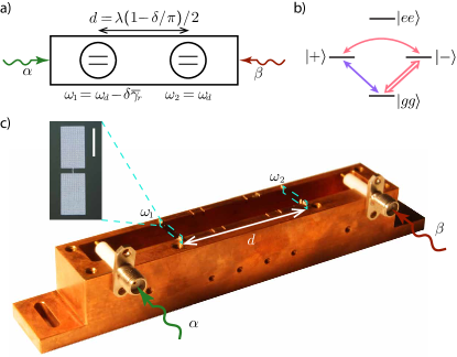
More specifically, we use two transmon-type superconducting qubits inserted in a rectangular copper waveguide (see Fig. 1c). The qubits are spatially separated by and are oriented to maximize coupling to the mode, which has a lower cutoff at . Two microwave connectors are positioned near each end of the waveguide, providing an interface between the microwave field inside the waveguide and the external circuitry. This ensures that the qubits are coupled to the continuum of the electromagnetic modes, thus emulating an effective 1D open space. Further technical details into the transmons and 1D waveguide design and characterization can be found in Ref. Zanner et al. .
The qubits were patterned by standard electron-beam lithographic techniques on high resistivity Si, followed by two angle shadow evaporation of Al. The design of the circuit consists of two planar capacitor plates connected via a line interrupted by a SQUID, playing the role of a tunable Josephson junction (see inset Fig. 1c). The transition frequencies of the qubits are then controlled via two current-biased superconducting coils.
As a result of the interaction with the waveguide modes, the excited state of a qubit spontaneously relaxes to its ground state at the radiative decay rate . This interaction leads to an almost full reflection of incident resonant microwaves by the qubit at low powers Astafiev et al. (2010), a phenomenon we use to determine the frequency of our qubits, their radiative decay rates and their decoherence due to other noise channels (refer to the Supplementary Material for more details). The rates were found to depend on the transition frequencies of the qubits , and varied between 60 MHz and 85 MHz for between 8.5 GHz and 9.0 GHz, respectively. The transmittance at resonance with the qubit was extinguished to less than at low powers of incident radiation, providing an upper bound on the qubits’ decoherence rate. This is characterized by the non-radiative decay and dephasing rates, which we measured to fall below for both qubits (detailed values can be found in the Supplementary Material). In order to determine the dependence of on the external magnetic field supplied by the coils, we performed transmission measurements while varying the magnetic field produced by each coil. We found the maximum frequencies of the qubits to be GHz and GHz.
When the two-atom system is driven by an external microwave field, their interaction depends strongly on the distance between qubits. Specifically, the interatomic distance determines the phase acquired by the drive when traveling from one qubit to the other, , where is the phase velocity in the waveguide and is the frequency of the drive. We tune in situ by setting the frequency of the incoming drive.
This interaction between the two qubits with the continuum of the electromagnetic modes in the waveguide gives rise to a field mediated exchange coupling between the qubits described via the term Lalumière et al. (2013) , where and (see Supplementary Material). At the phase matching condition (which, in the case of our system occurs when , with ), the exchange coupling between the qubits vanishes, so that the symmetric and antisymmetric states are perfectly degenerate. Furthermore, the antisymmetric state is bright, with a decay rate , whereas the symmetric state is dark, and hence fully decoupled from the interaction with the waveguide modes: Lalumière et al. (2013).
If the qubits are slightly detuned from the frequency , a resonant field at acquires a phase , where the small parameter characterizes the detuning from the phase matching condition. In this case, the exchange interaction between qubits does not vanish and lifts in turn the degeneracy between the states: , with . To leading order in , the dark state becomes quasi-dark with a decay rate , while the bright state decay rate remains unchanged: , Redchenko and Yudson (2014); Müller et al. (2017).
To break the inversion symmetry of our device and achieve nonreciprocal behavior, we set qubit 2 to be resonant with the incoming field, , whereas qubit 1 is set at , to compensate for the phase asymmetry introduced by the detuned (see Fig. 1a). This configuration opens an additional path of accessing the quasi-dark state , which can now be populated either directly by the incoming field () or indirectly through the bright state (), to which it is coupled via the exchange term (Fig. 1b).
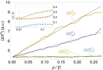
Our measurement setup allows us to drive the system from either the forward or reverse direction ( and driving, respectively, in Fig. 1a), with the reflected and transmitted fields simultaneously detected at both sides (refer to the Supplementary Material for extra details on the measurement setup). When driving in the forward direction, both channels to populate the quasi-dark state interfere constructively, giving rise to an excitation of . Neglecting non-radiative decay and dephasing (), the resulting steady state solution for the density operator of the qubits can be found analytically Müller et al. (2017) as for intermediate driving powers . Under these conditions, the system is predominantly trapped in the quasi-dark state and is therefore partially transparent to the incident signal, due to the extremely low saturability of .
If the system is driven in the reverse direction, both channels interfere destructively, the quasi-dark state remains unpopulated and the steady state solution is given by for powers . In this case, the incoming signal is reflected by the bright state and the two-qubit system behaves as a mirror.
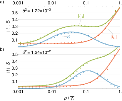
To illustrate the mechanism of nonreciprocal transmission, we tune the system to its optimal nonreciprocal configuration (up to experimental uncertainties) for two different values of the parameter : and , corresponding to driving frequencies and , respectively.
By controlling the driving power, we are able to probe three characteristic regimes of the device, featured in Fig. 2:
-
•
In the low power regime, , the device behaves reciprocally, reflecting most of the incoming radiation. In this regime, the degree of transmission suppression is only limited by the qubits’ decoherence and relaxation rates, and by the accuracy of qubit tuning to ensure that .
-
•
In the intermediate power regime, , the transmission amplitude in the forward direction increases and features the characteristic plateau predicted by theory Dai et al. (2015); Müller et al. (2017). The transmission amplitude in the reverse direction remains near zero independently of the value of and the system behaves nonreciprocally.
-
•
In the high power regime, , the bright state saturates, regardless of the driving direction, and the system returns to its reciprocal behavior.

In order to provide a metric of the isolation capabilities of the quantum diode, we calculate the diode efficiency used in Ref. Dai et al. (2015) which, in the ideal case of identical qubits and no decoherence, coincides with the definition of efficiency used in Refs. Fratini et al. (2014); Dai et al. (2015); Fratini and Ghobadi (2016). In spite of relatively low dephasing and non-radiative decay rates ( for both qubits), the maximum diode efficiency appears to be limited to , well below its ideal value Müller et al. (2017) of (see Fig. 2). This illustrates an experimental challenge in the realization of the quantum diode: since the nonreciprocal behavior relies on populating the quasi-dark state , the transition rate relevant for the system dynamics is . In our experiment, the dephasing and dissipation rates, , , are of the same order of magnitude of . This renders the effect of decoherence much more significative compared to single-qubit phenomena, whose dynamics evolve at the much faster rate .
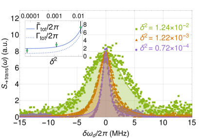
Further insights into the role of the quasi-dark state can be obtained by measuring the full spectrum of the elastically and inelastically scattered radiation. Notably, the measurement of the power spectral densities, in addition to a -like peak due to elastically (Rayleigh) scattered radiation (Fig. 3), features an additional broader peak, which we identify with radiation inelastically scattered off the quasi-dark state. The measured power spectrum agrees with our expectation of the total scattered power being a measure of the population of the quasi-dark state: as clearly seen from the measurement (Fig. 3), the scattered power is much greater when the system is driven in the forward direction.
Being able to control , we can tune the linewidth of the dark state emission, . Fig. 4 shows the power spectral densities of scattered radiation for three values of (here the elastic part has been omitted for clarity). As expected, the linewidth of the fluorescence spectra increases linearly with , following the increase in the decay rate of the dark state.
Our theoretical estimates predict that the width of the emission peak results from a combination of the dark state linewidth and broadening due to non-radiative and dephasing contributions. In the optimal diode conditions, the linewidth of the transmitted field when driving the system in the forward direction can be found analytically as (see Supplementary Material). In the experiment, the width of the inelastically scattered radiation is wider than predicted by MHz. This indicates an additional source of noise (presumably of technical origin) which could be mixed with the detected signal and results in an additional broadening of the scattered field.
By incorporating quantum-limited Josephson parametric amplifiers into our detection lines Eichler et al. (2014), we can measure time-domain single-shot data of the scattered fields and calculate its statistics. Our results show that the in-phase noise is higher when driving the system in the forward direction than in the reverse direction (see Supplementary Material). This is consistent with the statistics produced by replacing the system with a simple stochastic mirror, as theoretically predicted in Ref. Müller et al. (2017).
In conclusion, we experimentally realized a passive quantum nonreciprocal device comprised of a minimal number of constituents. At least two localized quantum emitters are required to break structural symmetry in 1D space, while a two-level atom is the simplest system presenting a nonlinear quantum behavior. The nonreciprocity relies on the interplay of the exchange interaction and the collective decay of quantum emitters leading to population trapping into an entangled quasi-dark state for a preferred driving direction. It is instructive to note that our device breaks some of the fundamental bounds derived for classical nonlinear devices Sounas and Alù (2017); Sounas et al. (2018) but is not immune to the dynamic reciprocity limitations Shi et al. (2015). While not yet sufficient for practical applications, our results open a path for the realization of more efficient nonreciprocal devices with multiple coherent qubits. The demonstrated mechanism of population trapping is also valuable for the development of protocols of remote entanglement stabilization.
Acknowledgements.
We thank Alexandre Roulet for useful discussions of our results and Shanhui Fan for helpful advise on dynamical reciprocity. We also thank Andrea Alù for reading our manuscript and providing valuable insights into nonlinear nonreciprocity. We acknowledge Andreas Wallraff and the ETHZ Qudev team for providing us with the parametric amplifier. This work was supported by the Australian Research Council under the Discovery and Centre of Excellence funding schemes (project numbers DP150101033, DE160100356, and CE110001013), and UQ Foundation Research Excellence Award. M.W. acknowledges support from the European Research Council (ERC) under the Grant Agreement 648011.References
- Pozar (1998) David M. Pozar, Microwave Engineering (Wiley, 1998).
- Viola and DiVincenzo (2014) Giovanni Viola and David P. DiVincenzo, “Hall effect gyrators and circulators,” Phys. Rev. X 4, 021019 (2014).
- Mahoney et al. (2017) A. C. Mahoney, J. I. Colless, S. J. Pauka, J. M. Hornibrook, J. D. Watson, G. C. Gardner, M. J. Manfra, A. C. Doherty, and D. J. Reilly, “On-chip microwave quantum hall circulator,” Phys. Rev. X 7, 011007 (2017).
- Müller et al. (2018) Clemens Müller, Shengwei Guan, Nicolas Vogt, Jared H Cole, and Thomas M Stace, “Passive On-Chip Superconducting Circulator Using a Ring of Tunnel Junctions,” Physical Review Letters 120, 213602 (2018).
- Estep et al. (2014) Nicholas A. Estep, Dimitrios L. Sounas, Jason Soric, and Andrea Alù, “Magnetic-free non-reciprocity and isolation based on parametrically modulated coupled-resonator loops,” Nature Physics 10, 923 (2014).
- Kerckhoff et al. (2015) Joseph Kerckhoff, Kevin Lalumière, Benjamin J. Chapman, Alexandre Blais, and K. W. Lehnert, “On-chip superconducting microwave circulator from synthetic rotation,” Phys. Rev. Applied 4, 034002 (2015).
- Barzanjeh et al. (2017) S. Barzanjeh, M. Wulf, M. Peruzzo, M. Kalaee, P. B. Dieterle, O. Painter, and J. M. Fink, “Mechanical on-chip microwave circulator,” Nature Communications 8, 953 (2017).
- Bernier et al. (2017) N. R. Bernier, L. D. Tóth, A. Koottandavida, M. A. Ioannou, D. Malz, A. Nunnenkamp, A. K. Feofanov, and T. J. Kippenberg, “Nonreciprocal reconfigurable microwave optomechanical circuit,” Nature Communications 8, 604 (2017).
- Fang et al. (2017) Kejie Fang, Jie Luo, Anja Metelmann, Matthew H. Matheny, Florian Marquardt, Aashish A. Clerk, and Oskar Painter, “Generalized non-reciprocity in an optomechanical circuit via synthetic magnetism and reservoir engineering,” Nature Physics 13, 465 (2017).
- Chapman et al. (2017) Benjamin J. Chapman, Eric I. Rosenthal, Joseph Kerckhoff, Bradley A. Moores, Leila R. Vale, J. A. B. Mates, Gene C. Hilton, Kevin Lalumière, Alexandre Blais, and K. W. Lehnert, “Widely tunable on-chip microwave circulator for superconducting quantum circuits,” Phys. Rev. X 7, 041043 (2017).
- Fan et al. (2012) Li Fan, Jian Wang, Leo T. Varghese, Hao Shen, Ben Niu, Yi Xuan, Andrew M. Weiner, and Minghao Qi, “An all-silicon passive optical diode,” Science 335, 447–450 (2012).
- Yi et al. (2015) Yu Yi, Chen Yaohui, Hu Hao, Xue Weiqi, Yvind Kresten, and Mork Jesper, “Nonreciprocal transmission in a nonlinear photonic‐crystal fano structure with broken symmetry,” Laser & Photonics Reviews, Laser & Photonics Reviews 9, 241–247 (2015).
- Sounas et al. (2018) Dimitrios L. Sounas, Jason Soric, and Andrea Alù, “Broadband passive isolators based on coupled nonlinear resonances,” Nature Electronics 1, 113–119 (2018).
- Peng et al. (2014) Bo Peng, Şahin Kaya Özdemir, Fuchuan Lei, Faraz Monifi, Mariagiovanna Gianfreda, Gui Lu Long, Shanhui Fan, Franco Nori, Carl M. Bender, and Lan Yang, “Parity-time-symmetric whispering-gallery microcavities,” Nature Physics 10, 394 (2014).
- Fratini et al. (2014) F. Fratini, E. Mascarenhas, L. Safari, J. Ph Poizat, D. Valente, A. Auffèves, D. Gerace, and M. F. Santos, “Fabry-perot interferometer with quantum mirrors: Nonlinear light transport and rectification,” Physical Review Letters 113, 1–5 (2014), arXiv:1410.5972 .
- Dai et al. (2015) Jibo Dai, Alexandre Roulet, Huy Nguyen Le, and Valerio Scarani, “Rectification of light in the quantum regime,” Physical Review A - Atomic, Molecular, and Optical Physics 92, 1–7 (2015), arXiv:1510.04494 .
- Fratini and Ghobadi (2016) F. Fratini and R. Ghobadi, “Full quantum treatment of a light diode,” Physical Review A - Atomic, Molecular, and Optical Physics 93, 1–5 (2016).
- Müller et al. (2017) Clemens Müller, Joshua Combes, Andrés Rosario Hamann, Arkady Fedorov, and Thomas M. Stace, “Nonreciprocal atomic scattering: A saturable, quantum Yagi-Uda antenna,” Physical Review A 96, 1–10 (2017), arXiv:1708.03450 .
- Roy (2010) Dibyendu Roy, “Few-photon optical diode,” Phys. Rev. B 81, 155117 (2010).
- Roy (2013) Dibyendu Roy, “Cascaded two-photon nonlinearity in a one-dimensional waveguide with multiple two-level emitters,” Scientific Reports 3, 2337 (2013).
- Mascarenhas et al. (2016) E. Mascarenhas, M. F. Santos, A. Auffèves, and D. Gerace, “Quantum rectifier in a one-dimensional photonic channel,” Phys. Rev. A 93, 043821 (2016).
- (22) Maximilian Zanner, Lukas Gruenhaupt, Silvia Diewald, Andrés Rosario Hamann, Arkady Fedorov, Alexey V. Ustinov, and Martin Weides, “Tunable superconducting qubit in a 3d waveguide,” Unpublished.
- Astafiev et al. (2010) O. Astafiev, A. M. Zagoskin, A. A. Abdumalikov, Yu. A. Pashkin, T. Yamamoto, K. Inomata, Y. Nakamura, and J. S. Tsai, “Resonance fluorescence of a single artificial atom.” Science 327, 840–843 (2010), arXiv:1002.4944 .
- Lalumière et al. (2013) Kevin Lalumière, Barry C. Sanders, A. F. van Loo, A. Fedorov, A. Wallraff, and A. Blais, “Input-output theory for waveguide qed with an ensemble of inhomogeneous atoms,” Phys. Rev. A 88, 043806 (2013).
- Redchenko and Yudson (2014) E. S. Redchenko and V. I. Yudson, “Decay of metastable excited states of two qubits in a waveguide,” Phys. Rev. A 90, 063829 (2014).
- Eichler et al. (2014) C. Eichler, Y. Salathe, J. Mlynek, S. Schmidt, and A. Wallraff, “Quantum-limited amplification and entanglement in coupled nonlinear resonators,” Phys. Rev. Lett. , 110502 (2014).
- Sounas and Alù (2017) Dimitrios L. Sounas and Andrea Alù, “Time-reversal symmetry bounds on the electromagnetic response of asymmetric structures,” Phys. Rev. Lett. 118, 154302 (2017).
- Shi et al. (2015) Yu Shi, Zongfu Yu, and Shanhui Fan, “Limitations of nonlinear optical isolators due to dynamic reciprocity,” Nature Photonics 9, 388 (2015).
- Combes et al. (2017) Joshua Combes, Joseph Kerckhoff, and Mohan Sarovar, “The SLH framework for modeling quantum input-output networks,” Advances in Physics: X 2, 784–888 (2017).
Appendix A Measurement setup
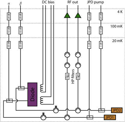
The nonreciprocal device, consisting of two superconducting qubits embedded in a 1D waveguide, is mounted on the 20 mK stage of a dilution refrigerator (purple box in Fig. 5). Two superconducting coils mounted around the waveguide serve to control the Josephson inductance of each of the qubits, which in turn determine their transition frequencies .
The device can be driven from any of the two input ports , , which are interfaced with the waveguide through the coupled ports of two directional couplers. The reflected and transmitted signals are then collected via the through port of the directional couplers, which allows us to detect them simultaneously. The two output signals are then parametrically amplified via two Josephson parametric dimers (JPD) Eichler et al. (2014) (orange boxes in Fig. 5) and further amplified via two high-electron-mobility transistor (HEMT) amplifiers.
Appendix B Single qubit SLH description
For a single atom in a waveguide, coupled symmetrically to both propagation directions, and driven with a coherent field from both sides, we can write, in analogy to Ref. Müller et al. (2017),
| (1) | ||||
| (2) |
where is the total radiative decay rate into the waveguide modes, is the strength of the coherent drive from the left, and is the driving field amplitude from the right. Here, Eq. (1) is written in a frame rotating at the drive frequency , and is the detuning between the atomic transition frequency and the drive. The master equation, including non-radiative decay and dephasing on the atom, is then
| (3) |
with the non-radiative decay rate and the dephasing rate .
To calculate the transmittance, we first find the steady-state of the master equation, . The transmission amplitude when driving from the left is then
| (4) |
where we defined the total atomic decay rate and dephasing rate , and is the power of the incoming drive.
Appendix C Single qubit spectroscopy
We characterize the radiative , non-radiative , and dephasing rates of each individual qubit by performing spectroscopic measurements. In order to achieve this, we detune one of the qubits below the cutoff of the waveguide and set the target qubit to frequency . We then sweep a low power microwave tone around and detect the transmitted electric field . Next, we calculate the transmission amplitude , where is the amplitude of the incident electric field. The transmittance is then least-squares fitted to Eq. (4) to extract all relevant parameters for each qubit individually. We repeat this procedure for a range of target frequencies for each qubit in order characterize their operational points. The radiative decay rates are found to vary between MHz and MHz for qubit frequencies between 8.5 GHz and 9.5 GHz, whereas throughout this range. See Table 1 for some particular values.
| 8.6 GHz | 8.8 GHz | |
|---|---|---|
| (MHz) | 71.3039 | 62.4261 |
| (MHz) | 72.4299 | 73.1158 |
| (kHz) | 211.4 | 74.7 |
| (kHz) | 191.1 | 64.0 |
Appendix D Two-qubit master equation
Following Ref. Müller et al. (2017), we write the master equation for the two-qubit density matrix
| (5) |
where , and
Here are the amplitudes of the right- and left-moving fields, respectively, and the operators and represent the right- and left-moving output fields. The input field is at frequency , is the phase shift acquired by the drive when traveling between the atoms, and , form part of the SLH triplet Combes et al. (2017) described by
where indexes the atoms, is the eigenfrequency of atom in the frame rotating at , and is its radiative decay rate. We defined the atomic lowering operator as .
The right-moving steady-state output field is then found as , where is the steady state solution of Eq. 5, , with input amplitudes . Finally, we calculate the forward-driven transmission amplitude as . Similarly, the reverse-driven transmission amplitude equates to .
Appendix E Bright and dark states decay rates for
Following the notation of Ref. Müller et al. (2017), we write the dissipative parts of the SLH dissipators as
where we assumed the general case of , and we used the dark and bright state annihilation operators
In the experimentally relevant limit where , , and , we can rewrite the the sum of dissipators in the master equation as
| (6) |
with and , and where we defined .
Appendix F Linewidth of the transmitted field
The linewidth of the dark state emission is given by the lifetime of the dark state population , i.e., the rate at which it decays towards its equilibrium state. In the diode regime, the dark state is inverted, in that . Without nonradiative decay or additional dephasing, from Ref. Müller et al. (2017) we find the decay rate of the dark state into the ground-state in the diode regime as . In the same regime, the excitation rate of exciting the ground state into the dark state is , leading to the ideal steady-state dark state population of .
In the non-ideal case, assuming symmetric nonradiative and dephasing as in Eq. (5), and focusing on their contributions to the dark state decay rate, one finds
| (7) | ||||
| (8) |
leading to the total decay rate of the dark state . The dark state lifetime is then and the experimentally measured total linewidth of the emitted radiation is given by .
Appendix G Output field statistics in the diode configuration
When driving the diode in the forward direction and powers , the system is confined to the manifold (up to order ). The two-atom system can be found in the ground, reflecting state with probability or in the quasi-dark, transparent state with probability . As demonstrated in Ref. Müller et al. (2017), the statistics of the scattered fields in the diode regime can be replicated by a flapping mirror model, i.e., by a system composed of a stochastic mirror that can flip into the path of the signal (reflecting state, ) with probability , or out of the path (transmitting state, ) with probability . In this scenario, the transmitted in-phase heterodyne signal can be modeled as , where is the transmitted signal, which depends on the driving amplitude and the state of the mirror , and encompasses both quantum and technical noise contributions. Assuming uncorrelated white noise, such that , the variance of the in-phase signal is given by
Since , , which gives
On the other hand, the quadrature signal remains unchanged regardless of the state of the mirror , and hence . In both the forward- and reverse-driving configurations, the noise in the reflected and transmitted signals is the same since .
We incorporate quantum-limited Josephson parametric amplifiers into our detection lines in order to measure time-domain single-shot data of the scattered fields and compare our results to the flapping mirror model (see Fig. 6). When forward-driving the system with powers , the quasi-dark state population reaches a constant non-zero value (up to order ), and hence we observe that the in-phase noise scales linearly with power: . As expected, the quadrature noise remains at its constant value for both driving directions , where and are the technical and quantum noise contributions to the signal, respectively. The in-phase noise for the reverse driving scattered field also increases linearly with power, although at a different rate, consistent with a smaller population of the quasi-dark state and with our simulations.