Nonreciprocal Cavities and the Time-Bandwidth Limit
Abstract
The time-bandwidth limit inherently relates the lifetime of a resonance and its spectral bandwidth, with direct implications on the maximum storage time of a pulse versus its frequency content. It has been recently argued that nonreciprocal cavities may overcome this constraint, by breaking the strict equality of their incoupling and outcoupling coefficients. Here, we generally study the implications of nonreciprocity on resonant cavities and derive general relations, stemming from microscopic reversibility, that govern their dynamics. We show that nonreciprocal cavities do not provide specific advantages in terms of the time-bandwidth limit, but they may have other attractive properties for nanophotonic systems.
The demands of integrated photonic circuits have motivated a large body of research with the objective of scaling down and integrating crucial optical components for information processing Reed et al. (2010); Sounas and Alù (2017); Ayata et al. (2017); Lira et al. (2012); Green et al. (2007); Bi et al. (2011); Phare et al. (2015); Xu et al. (2005); Shen et al. (2015a); Manolatou et al. (1999); Grote et al. (2013); Feng et al. (2012); Sounas and Alù (2014). A common approach to enable small footprints is to use resonant cavities Bi et al. (2011); Phare et al. (2015); Xu et al. (2005); Shen et al. (2015a); Manolatou et al. (1999); Grote et al. (2013); Feng et al. (2012); Sounas and Alù (2014), which can dramatically enhance light-matter interactions by storing light over the resonance lifetime. This reduced footprint, however, comes at the cost of operational bandwidth: a single resonant cavity adheres to a strict correspondence between its resonance bandwidth and its lifetime SI : . As a relevant example in nanophotonics, resonators are frequently used to impart delays on optical pulses, given their ability to temporarily store light. The strict relation between lifetime and bandwidth of a cavity implies a trade-off between the spectral bandwidth of the pulse that can be stored and the temporal delay that can be imparted on it. Larger structures (e.g., arrangements of multiple cavities Yariv et al. (1999)) may partially relax this bound, but still follow an analogous trade-off between the delay-bandwidth product and the overall footprint Miller (2007). Recent approaches to overcome this limitation have relied on time-varying systems Yanik and Fan (2004); Xu et al. (2007); Minkov and Fan (2018) or on nonlinearities Lannebère and Silveirinha (2015), but efficiently implementing these schemes often becomes technologically challenging, or imposes limitations in their operation.
A thought-provoking proposal to alleviate the strict correspondence between bandwidth and lifetime of linear, time-invariant structures has been recently been put forward, based on breaking reciprocity with a static magnetic bias Tsakmakidis et al. (2017). The authors argue that the supported bandwidth scales with the rate at which energy enters the system, while the lifetime is inversely proportional to the rate at which energy exits it. These rates are known to be equal in reciprocal cavities Haus (1984), resulting in the mentioned time-bandwidth relation, but Ref. Tsakmakidis et al. (2017) suggests that nonreciprocal cavities may support different input and output rates, and thus can surpass this limit. While this idea would have a large impact on many photonic applications relying on resonances, it raises concerns regarding its thermodynamic validity Tsang (2018): unequal input and output rates violate energy conservation in a passive system.
Inspired by this proposal, in the following we develop a general temporal coupled-mode theory broadly describing the dynamics of nonreciprocal cavities, and show that incoming and outgoing rates are always strictly related through a number of identities that generalize the known relations in reciprocal systems. For example, we prove that in nonreciprocal cavities the total rates must always be equal in magnitude. We also show that time-bandwidth product is strictly limited in any linear, time-invariant cavity, independent of whether it is reciprocal or not, and provide numerical demonstrations. We also derive bounds for the coupling coefficients of nonreciprocal cavities, and design cavities operating at these bounds.
We start our discussion by studying a general resonant cavity with complex mode amplitude a connected to n ports, with incoming complex amplitudes . Such a system is described by the equation of motion Haus (1984); Suh et al. (2004)
| (1) |
where is the vector of input coupling coefficients, is the eigenfrequency, is the radiation loss rate into the ports, and is the intrinsic loss rate due to absorption inside the cavity. The amplitudes are normalized such that is the stored energy in the cavity and is the incoming power at port . The amplitude of the reflected modes is given by
| (2) |
Here, is the direct reflection coefficient, which is unitary in the absence of loss, and is the output coupling coefficient from the cavity mode into the ports. Power conservation ensures that Suh et al. (2004). In addition, by assuming time-harmonic excitation () we find from Eq. 1:
| (3) |
Eqs. 1-3 and the relation apply to both reciprocal and nonreciprocal cavities. In addition, reciprocity dictates that and (asterisk denotes complex conjugate) Suh et al. (2004), which follow from time-reversal symmetry. However, if the cavity is biased with a quantity odd symmetric under time-reversal, these two identities do not apply, as the time-reversed system is no longer equivalent to the original one. In the following, we therefore denote the coefficients in the time-reversed scenario with a tilde, as , and . As a first important result of this work, we show that, if the resonant frequency is not perturbed by a time-reversal operation, the following relationships necessarily hold for both reciprocal and nonreciprocal linear time-invariant systems (proofs are provided in SI ):
| (4a) | |||
| (4b) | |||
| (4c) | |||
| (4d) | |||
| (4e) | |||
| (4f) |
Here the superscripts and denote the regular and Hermitian transpose. These relationships are markedly different from the regular expressions for reciprocal systems Suh et al. (2004); not , particularly because they involve the original system and its time-reversed counterpart (which, as we will show, can differ strongly in its response). This is a consequence of microscopic reversibility Casimir (1945): while the system itself is not time-reversal symmetric, global time-reversal invariance still applies, and the original and time-reversed systems are necessarily related.
Eq. 4f is the fluctuation-dissipation relation, relating dissipation () to how the cavity responds to external fluctuations () SI ; Tsang (2018); Gardiner (2003). Together with Eq. 4e, this relation is arguably the most important result for the following discussions, as they put stringent restrictions on the achievable asymmetry in the coupling coefficients: while it is possible to achieve at any individual port, the positive-definite norm of and has to be equal (see Eq. 4f). Finally, we note that Eqs. 4 readily reduce to the known identities for reciprocal cavities Suh et al. (2004), if we assume that the system is time-reversal symmetric, i.e. , , and .
Eqs. (4) have important general consequences in the context of nonreciprocal cavities Yu et al. (2008); Liu et al. (2016). As a relevant example, consider a nonreciprocal waveguide supporting a unidirectional mode, i.e., no backward channel into which energy can be reflected, and terminated into a cavity, similar to geometries studied in Luukkonen et al. (2012); Hadad and Steinberg (2013) and shown schematically in Fig. 1a. For the nonreciprocal waveguide, we use the interface between a magnetized magneto-optic semiconductor and a dielectric material Yu et al. (2008); Brion et al. (1972); Camley (1987); Davoyan and Engheta (2013), which for the combination InSb and Si is known to support a unidirectional surface wave around 1.5 THz Tsakmakidis et al. (2017); Shen et al. (2015b, c) (see all geometry details in SI ). The waveguide is terminated onto a resonant lossless rectangular cavity (20 by 30 m in size), enclosed by perfect electric conducting (PEC) walls, connected through a small aperture (0.5 m).
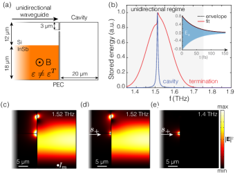
We use a home-built FDTD code SI to excite the unidirectional waveguide with a broadband pulse (=1.5 THz, =0.16 THz), and record the fields inside the cavity as a function of time. Fig. 1b shows the Fourier transform of the electric field induced at the center of the cavity (blue line), showing a sharp Lorentzian resonance at 1.52 THz, with linewidth rad/s. When exciting the cavity from the interior, we find exactly the same decay rate rad/s by examining the field decay (inset of Fig. 1b). This should not be surprising, as Eq. (3) applies independent of whether the system is reciprocal or not, and ensures that the bandwidth of any linear cavity is solely determined by the decay rate , i.e., by the internal loss and the outcoupling coefficients . This is supported by the observation that the fields at the termination outside the cavity have a much larger bandwidth (Fig. 1b, red line), equal to the bandwidth of the incident pulse, but that these fields cannot be forced into the cavity. In other words, as a first important consequence of the previous theory, the time-bandwidth product of any linear cavity satisfies , and it is controlled only by the output coupling coefficient . The incoupling coefficient , according to Eq. (3), only controls the amount of stored energy in the resonator.
More surprising is that the cavity has a finite decay rate, despite the fact that it is both lossless () and connected to a waveguide that does not support backward modes (). While the decay process is not immediately apparent, it is consistent with Eq. 4f, which requires that if the cavity can be excited it must also be able to decay to maintain equilibrium. This paradox can be resolved by inspecting the electric field distribution during decay (without an external excitation), shown in Fig. 1c. We notice a strong hot spot at the wedge formed by the Si/InSb waveguide and the PEC termination which, given the finite material loss in InSb, dissipates all incoming energy and thus sustains the cavity decay. We also observe this hotspot when exciting from the waveguide port, both on- and off-resonance (Figs. 1d,e) Tsakmakidis et al. (2017); Shen et al. (2015c); Ishimaru (1962); Chettiar et al. (2014); Marvasti and Rejaei (2017). Since both the cavity and the input port can excite this wedge mode, they interfere in the process of dissipation (as evidenced in the bump through the resonance in the red curve in Fig. 1b). As a result, the wedge mode cannot be treated as a simple internal loss process, as , but needs to be treated as an additional output port SI . Then, writing and for the input and output coefficients for the radiation from/into the waveguide and wedge, respectively, we find that is permitted, while is simultaneously satisfied. In other words, this means that while the input and output coefficients may differ at each individual port, but the total input and output rates must always be equal. It follows that in the special case of a one-port system, like the one generally described in Tsakmakidis et al. (2017), the input and output coefficients must necessarily be equal in magnitude, but they may still differ in phase.
One may wonder what happens in the limit in which material loss in the unidirectional waveguide is zero, for which the wedge mode is expected to become non-dissipative. This problem has been extensively discussed in the literature (see Ishimaru (1962); Lax and Button (1955); Kales (1956); Seidel (1957); Bresler (1960) for a selection), and has been referred to as the “thermodynamic paradox”, since it was believed to produce an inconsistency between Maxwell’s equations and thermodynamics. The paradox was resolved by Ishimaru [36], who pointed out that the field distribution at the termination of a unidirectional waveguide is non-integrable if assumed lossless, and it sustains finite absorption even in the limit of vanishing material loss. A lossless terminated one-way waveguide is actually an ill-posed boundary-value problem, as Maxwell’s equations do not guarantee a unique solution in the ideal lossless scenario Harrington (2001). The correct solution is found in the limit of vanishing loss, for which the dissipation rate remains finite. Aside from the wedge mode in this terminated unidirectional waveguide Tsakmakidis et al. (2017); Shen et al. (2015c); Ishimaru (1962); Chettiar et al. (2014); Marvasti and Rejaei (2017), similar singularities that support finite absorption in the limit of vanishing material loss can be found in other extreme electromagnetic systems Silveirinha and Engheta (2007); Estakhri and Alù (2013), and are a reminder that ideal lossless scenarios should be considered an artifact in electromagnetics and may lead to singularities or non-unique solutions.
While Eqs. 1-4 strictly prove that the time-bandwidth product of a linear time-invariant cavity is always equal to 2, and that therefore it is impossible to force broadband fields into a long-lived resonance, independent of reciprocity, Refs. Tsakmakidis et al. (2017); Shen et al. (2015c); Ishimaru (1962); Chettiar et al. (2014); Marvasti and Rejaei (2017) do demonstrate broadband focusing of photons in an ultra-small volume near the termination, whose decay rate is unrelated to, and can be much slower than, the excitation. Consistently, our simulations confirm focusing of incident photons at the wedge (Figs. 1d,e) over a wide range of frequencies (Fig. 1b, red line), irrespective of the properties of the cavity resonance. We stress however that this broadband focusing is not directly a consequence of nonreciprocity: adiabatically tapered terminated plasmonic waveguides Stockman (2004); Pile and Gramotnev (2006); Verhagen et al. (2008), which slowly focus the incoming fields towards an apex, perform the same function. The benefit of applying nonreciprocity is that the termination is automatically matched due to the absence of a backwards mode in the waveguide Luukkonen et al. (2012); Hadad and Steinberg (2013), relaxing the need for a carefully designed adiabatic transition that minimizes reflections.
After having demonstrated that nonreciprocity is not beneficial to break the trade-off between lifetime and bandwidth in linear, time-invariant cavities, in the following we will explore to what degree the input and output coupling may be made different in nonreciprocal cavities, and what functionalities can be enabled by such asymmetry. Achieving asymmetry in the coupling coefficients is important for e.g. circulators Pozar (2012) and unidirectional heat transfer Zhu and Fan (2016); Zhu et al. (2018). In the previous example, the absence of a backwards mode ensured . However, we will now show that, even if there is a backwards mode, the input and output coefficients at a given port differ significantly in nonreciprocal cavities. To do so, we examine the same system as in Fig. 1, but now excited in the bidirectional regime at frequencies just below 1.25 THz. We therefore tune the cavity to 1.24 THz, by increasing the cavity size to 35.4 by 20 m (see SI for geometry details). With full-wave simulations we retrieve the complex cavity and reflection amplitudes, and through a fitting procedure we obtain and (see SI for spectra and fits). As expected, now because of the presence of a propagating backward mode, but the two magnitudes are shown to be significantly different due to the presence of the wedge mode. When operating just below the unidirectional gap the system is still strongly asymmetric (in this case the forward and backward effective indices are 4.47 and 9.92 respectively), and it is to be expected that, as the asymmetry reduces, and will also approach each other.
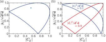
While the input and output coefficients at the input port may be made different, both in magnitude and phase, Eq. 4f requires the total rates of the cavity must be the same, and in the system under consideration this is guaranteed by the wedge mode, which balances out any asymmetry in and . Interestingly, this is, however, not the only requirement: the direct pathway places an additional bound on these coefficients through Eq. 4e. For a general two-port system with and , we find using the Cauchy-Schwarz inequality:
| (5) |
where due to power conservation. An example of this bound is shown in Fig. 2a as a function of for ( quantifies the fraction of radiated power flowing towards port as the cavity decays). This specific example corresponds to the previously discussed bidirectional system, where the subscript indicates radiation into/from the port (e.g. ). The cross in the figure highlights the magnitude of and for this geometry at 1.24 THz, falling within the bounds delimited by the solid line. The shape of the bound on strongly depends on and : Fig. 2b displays similar bounds for and . In the system of Fig. 1 he absence of a backward mode dictates that both and , in which case Eq. 5 becomes : as expected, power can only enter the cavity at the rate in which it is dissipated by the wedge mode or other output port. Similarly, if , which implies that the two ports are not directly connected, Eq. 5 requires that , and thus input and output coefficients for each port can be nonreciprocal only in phase, as in a gyrator. This is a consequence of the fact that the ports only exchange power with the cavity itself, and hence cannot compensate for any asymmetry in its response.
Having discussed the general bounds on the input and output coupling coefficients of nonreciprocal cavities, we now investigate an extreme condition allowed by the bounds in Eq. 5, which may provide interesting functionalities for nanophotonic systems. We consider the scenario of a cavity connected to a bidirectional waveguide () that cannot be excited from its input port (), but that decays into it (). To design such a cavity, it is sufficient to place its opening at a position with complete destructive interference between the forward and backward modes, as shown in Fig. 3a. Since nonreciprocal waveguides have different forward and backward field profiles [50], we need to ensure that the backward mode has higher fields at the top PEC plate, and that the reflection coefficient compensates for differences in magnetic field amplitude. As shown in Fig. 3b, we achieve this condition by reverting the magnetic field bias with respect to the previous examples and optimizing of the reflectivity of the waveguide termination, using a dissipative surface impedance, to achieve . The necessity of a reduced reflection coefficient is consistent with our previous finding, in Eq. 5, that a nonreciprocal response in magnitude can only be achieved if .
We now find a locally vanishing magnetic field at the top PEC wall (Fig. 3a), implying that a cavity coupled to the waveguide at that location cannot be excited. In Fig. 3c, we place a cavity above the waveguide with its opening at the location of destructive interference, and a forward wave impinging from the channel indeed does not excite the cavity. If the waveguide were reciprocal, a zero in magnetic field at the cavity opening when excited from the port would imply that the cavity also cannot decay into the port. However, in the nonreciprocal case this is not so: if we excite the cavity from inside, we see it decay freely towards the output port (Fig. 3d). This is a result of the fact that, due to nonreciprocity and the different profiles of the forward and backward modes of the waveguide, for excitation from inside the cavity these modes are excited with different amplitudes at the aperture.
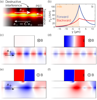
Interestingly, as indicated by Eqs. 4c,d we can swap the values of and by reversing the direction of the magnetic field bias (which is equivalent to a time-reversal operation). This is shown in Figs. 3e,f, which present the same structure but with a opposite magnetic bias. It can be seen that the cavity now can be efficiently excited from the port (Fig. 3e), but when the cavity is excited from inside it decays only towards the termination and get dissipated there, despite the presence of a backward propagating mode. It is interesting to point out that, in contrast to the example in Fig. 1, here while — even though there is an available backwards mode, the cavity cannot couple to it.
To conclude, in this paper we have presented a general theoretical framework describing the dynamics of nonreciprocal cavities. Our results show that, for single port systems, and can only differ in phase, and for and at any individual port to be different in magnitude at least one additional channel is necessary. This is consistent with the general principle that to realize a linear isolator it is necessary to have a loss channel Carlin (1955); Gamo (1959) or an additional radiative port, as in a circulator. For systems with multiple ports we have shown that the sums of all input and output rates are necessarily equal: . This implies that non-reciprocal cavities still follow strict bounds on their input and output coefficients, but nonetheless can be employed to realize highly non-trivial phenomena, such as cavities that can be pumped only one-way and release the energy into a totally different channel. We have shown that under a reversal of the magnetic field bias the functionalities of such a system strictly reverse. Finally, we have shown that the bandwidth of a linear, time-invariant cavity is always inversely proportional to its decay rate, both in reciprocal and nonreciprocal systems. The decay rate of a cavity is solely determined by the internal loss and the outcoupling coefficients , not by the incoupling rate. Thus, it is not possible to force broadband fields into a long-lived resonance, independent of reciprocity, for which we have provided a numerical demonstration. Our results clarify claims that non-reciprocity may alleviate the strict limitations imposed by the trade-off between delay and bandwidth in photonic systems, and may help envisioning new efficient nonreciprocal components for, e.g., information processing, unidirectional transport, and thermal rectifiers. This work was supported by the Air Force Office of Scientific Research.
References
- Reed et al. (2010) G. T. Reed, G. Mashanovich, F. Y. Gardes, and D. J. Thomson, Nature Photonics 4, 518 (2010).
- Sounas and Alù (2017) D. L. Sounas and A. Alù, Nature Photonics 11, 774 (2017).
- Ayata et al. (2017) M. Ayata, Y. Fedoryshyn, W. Heni, B. Baeuerle, A. Josten, M. Zahner, U. Koch, Y. Salamin, C. Hoessbacher, C. Haffner, D. L. Elder, L. R. Dalton, and J. Leuthold, Science 358, 630 (2017).
- Lira et al. (2012) H. Lira, Z. Yu, S. Fan, and M. Lipson, Physical Review Letters 109, 1 (2012).
- Green et al. (2007) W. M. Green, M. J. Rooks, L. Sekaric, and Y. A. Vlasov, Optics Express 15, 17106 (2007).
- Bi et al. (2011) L. Bi, J. Hu, P. Jiang, D. H. Kim, G. F. Dionne, L. C. Kimerling, and C. A. Ross, Nature Photonics 5, 758 (2011).
- Phare et al. (2015) C. T. Phare, Y.-H. Daniel Lee, J. Cardenas, and M. Lipson, Nature Photonics 9, 511 (2015).
- Xu et al. (2005) Q. Xu, B. Schmidt, S. Pradhan, and M. Lipson, Nature 435, 325 (2005).
- Shen et al. (2015a) B. Shen, P. Wang, R. Polson, and R. Menon, Nature Photonics 9, 378 (2015a).
- Manolatou et al. (1999) C. Manolatou, M. J. Khan, S. Fan, P. R. Villeneuve, H. A. Haus, and J. D. Joannopoulos, IEEE Journal of Quantum Electronics 35, 1322 (1999).
- Grote et al. (2013) R. R. Grote, J. B. Driscoll, and R. M. Osgood, Jr., Optics Letters 38, 3001 (2013).
- Feng et al. (2012) S. Feng, T. Lei, H. Chen, H. Cai, X. Luo, and A. W. Poon, Laser and Photonics Reviews 6, 145 (2012).
- Sounas and Alù (2014) D. L. Sounas and A. Alù, ACS Photonics 1, 198 (2014).
- (14) Supplementary Information to this Letter .
- Yariv et al. (1999) A. Yariv, Y. Xu, R. K. Lee, and A. Scherer, Optics Letters 24, 711 (1999).
- Miller (2007) D. A. B. Miller, Physical Review Letters 99, 203903 (2007).
- Yanik and Fan (2004) M. F. Yanik and S. Fan, Physical Review Letters 92, 083901 (2004).
- Xu et al. (2007) Q. Xu, P. Dong, and M. Lipson, Nature Physics 3, 406 (2007).
- Minkov and Fan (2018) M. Minkov and S. Fan, Physical Review B 97, 060301 (2018).
- Lannebère and Silveirinha (2015) S. Lannebère and M. G. Silveirinha, Nature Communications 6, 8766 (2015).
- Tsakmakidis et al. (2017) K. L. Tsakmakidis, L. Shen, S. A. Schulz, X. Zheng, J. Upham, X. Deng, H. Altug, A. F. Vakakis, and R. W. Boyd, Science 356, 1260 (2017).
- Haus (1984) H. Haus, Waves and Fields in Optoelectronics (Prentice-Hall, Englewood Cliffs, NJ, USA, 1984).
- Tsang (2018) M. Tsang, Optics Letters 43, 150 (2018).
- Suh et al. (2004) W. Suh, Z. Wang, and S. Fan, IEEE Journal of Quantum Electronics 40, 1511 (2004).
- (25) It is important to note a conceptual difference in coupled-mode theory when dealing with non-reciprocal systems: if corresponds to the coupling coefficient of a given forward mode to the resonance, then usually is the coupling coefficient to the backward version of the same mode. However, in nonreciprocal systems a subtler definition of these coefficients is required, as the waveguide might be unidirectional, or have largely different propagation properties in the two directions. Here, we assume (without loss of generality) that port supports at least one forward or backward mode, and at most both. If there is no forward or backward mode, we set or respectively .
- Casimir (1945) H. B. G. Casimir, Reviews of Modern Physics 17, 343 (1945).
- Gardiner (2003) C. Gardiner, Handbook of Stochastic Methods (3rd edition) (Springer, 2003).
- Yu et al. (2008) Z. Yu, G. Veronis, Z. Wang, and S. Fan, Physical Review Letters 100, 023902 (2008).
- Liu et al. (2016) K. Liu, A. Torki, and S. He, Optics Letters 41, 800 (2016).
- Luukkonen et al. (2012) O. Luukkonen, U. K. Chettiar, and N. Engheta, IEEE Antennas and Wireless Propagation Letters 11, 1398 (2012).
- Hadad and Steinberg (2013) Y. Hadad and B. Z. Steinberg, Optics Express 21, A77 (2013).
- Brion et al. (1972) J. J. Brion, R. F. Wallis, A. Hartstein, and E. Burstein, Physical Review Letters 28, 1455 (1972).
- Camley (1987) R. Camley, Surface Science Reports 7, 103 (1987).
- Davoyan and Engheta (2013) A. R. Davoyan and N. Engheta, Physical Review Letters 111, 257401 (2013).
- Shen et al. (2015b) L. Shen, Y. You, Z. Wang, and X. Deng, Optics Express 23, 950 (2015b).
- Shen et al. (2015c) L. Shen, X. Zheng, and X. Deng, Optics Express 23, 11790 (2015c).
- Ishimaru (1962) A. Ishimaru, Unidirectional waves in anisotropic media and the resolution of the thermodynamic paradox, Tech. Rep. (Air Force Cambridge Research Laboratories, Bedford, Mass., 1962).
- Chettiar et al. (2014) U. K. Chettiar, A. R. Davoyan, and N. Engheta, Optics letters 39, 1760 (2014).
- Marvasti and Rejaei (2017) M. Marvasti and B. Rejaei, Journal of Applied Physics 122, 233901 (2017).
- Lax and Button (1955) B. Lax and K. J. Button, Journal of Applied Physics 26, 1186 (1955).
- Kales (1956) M. Kales, Proceedings of the IRE 44, 1403 (1956).
- Seidel (1957) H. Seidel, Journal of Applied Physics 28, 218 (1957).
- Bresler (1960) A. Bresler, IEEE Transactions on Microwave Theory and Techniques 8, 81 (1960).
- Harrington (2001) R. F. Harrington, Time-Harmonic Electromagnetic Fields (Wiley-IEEE, 2001).
- Silveirinha and Engheta (2007) M. G. Silveirinha and N. Engheta, Physical Review B 76, 245109 (2007).
- Estakhri and Alù (2013) N. M. Estakhri and A. Alù, Physical Review B 87, 205418 (2013).
- Stockman (2004) M. I. Stockman, Physical Review Letters 93, 137404 (2004).
- Pile and Gramotnev (2006) D. F. P. Pile and D. K. Gramotnev, Applied Physics Letters 89, 2004 (2006).
- Verhagen et al. (2008) E. Verhagen, A. Polman, and L. K. Kuipers, Optics Express 16, 45 (2008).
- Pozar (2012) D. M. Pozar, Microwave Engineering, 4th ed. (Wiley, 2012).
- Zhu and Fan (2016) L. Zhu and S. Fan, Physical Review Letters 117, 134303 (2016).
- Zhu et al. (2018) L. Zhu, Y. Guo, and S. Fan, Physical Review B 97, 094302 (2018).
- Carlin (1955) H. Carlin, Proceedings of the IRE 43, 608 (1955).
- Gamo (1959) H. Gamo, IRE Transactions on Circuit Theory 6, 283 (1959).