On-resonance material fast light
Abstract
We theoretically revisit the problem of the propagation of coherent light pulses through a linear medium when the carrier frequency of the pulses coincides with the minimum of a narrow dip in the medium transmission. Considering realistic contrasts between the maximum and minimum transmission of the medium and incident pulses of strictly finite duration, we combine temporal and spectral approaches to obtain analytical expressions of the transmitted pulse that reproduce the main features of the exact numerical solutions derived by fast Fourier transform. A special attention is paid to the advance of the pulse maximum over that of a pulse covering the same distance in vacuum and the ratio of this advance to the pulse duration (fractional advance) is optimized.
I Introduction
Fast light currently refers to situations in which a smooth pulse of coherent light is transmitted by a linear optical system in such a manner that the maximum of the output pulse anticipates that of a pulse having covered the same distance in vacuum. As extensively discussed in the literature (see, e.g., chi97 ; bo02 ), the phenomenon is not at odds with the relativistic causality. It appears in particular that the maximum of the output pulse is not as a direct reflection of that of the input pulse but results from the action of the system on the early part of the latter. A direct experimental evidence of this point is reported in to14 . Fast light can be obtained when the system transmission displays a well-marked, narrow dip at the carrier frequency of the input pulse ma05 . Note however that this condition is not always sufficient. For optical systems that are not minimum-phase-shift pa87 , in particular those involving mirrors wa02a ; ma16a or polarizers so03 ; bru04 ; ma16b , it may even occur that a same transmission profile leads to either fast or slow light. In the case of purely propagative systems as considered in the following, fast light simply originates in the dispersive properties of the medium (material fast light) and the Kramers-Kronig relations apply in their common form. Even in this case a dip in the transmission profile does not always entail fast light. For instance when the dip corresponds to a minimum of transmission between two gain lines, there is a range of parameters for which there is no fast light whatever the dip depth is ma03 .
The simplest way to observe material fast light is to exploit the anomalous dispersion associated with an isolated absorption line of a passive medium. Experiments have been performed on various materials including semi-conductor chu82 , molecular gas se85 , atomic vapour at room temperature ta03 , hot atomic vapour ke12 and clouds of cold atoms je16 , with propagation distances going from 390 nanometers ke12 to 24 meters se85 . In order to control the pulse advance, the transmission dip is artificially created in other experiments by applying supplementary fields interacting non linearly with the medium and taking advantage of the phenomena of electromagnetically induced absorption ak02 ; go02 ; ki03 ; ka04 ; mi04 ; br08 ; ak10 , Raman effect wa00 ; ste03a , Brillouin effect chi07 and four wave mixing gla12 ; sw17 .
In most experimental reports on material fast light, the emphasis is made on the absolute value of the advance of the pulse maximum over that of a pulse propagating in vacuum and on the corresponding value of the velocity often confused with the group velocity. In fact the true experimental challenge is to obtain advances which are significant compared to the pulse duration with acceptable pulse distortion. On the other hand, in the numerous theoretical papers on the subject, the proof of fast light is generally reduced to that of a superluminal group velocity without simulation evidencing a visible advance of the pulse maximum.
The present article is theoretical but devotes a special attention to actual or feasible experiments. Its purpose is to clarify some points about material fast light and to examine what are the practical limitations to the phenomenon, Mother Nature resisting to a violation of her principles even when this violation is only apparent. To do so, we come back to the basic system consisting in a passive medium with an isolated absorption line chu82 ; se85 ; ta03 ; ke12 ; je16 . The simplicity of this system, favourable from an experimental viewpoint, will enable us to obtain analytical results. Insofar as the performances of the medium are essentially determined by the contrast between its maximum and minimum of transmission ma05 , it may be reasonably expected that these results have some generality. Anticipating a more extensive discussion, we note here that contrast exceeding 40 dB has been actually used in absorbing media se85 whereas it seems difficult to use an equivalent optical gain without generating serious instabilities ste94 ; ste03b .
The arrangement of our paper is as follows. In Sec.II, we introduce the basic equations of the problem and analyse their physical meaning by privileging the temporal approach. Asymptotic solutions obtained in the short and long pulse limits are given in Sec.III and Sec.IV. Section V is devoted to the optimization of the fractional advance of the pulse maximum, ratio of this advance to the pulse duration. The results are discussed in Sec.VI and we conclude in Sec.VII by summarizing the main points.
II GENERAL ANALYSIS
When coherent light pulses with a slowly varying envelope propagate in a linear medium of thickness , the envelope of the output pulse can be deduced from the envelope of the incident pulse by the general relation:
| (1) |
where is the impulse response of the medium and designates a convolution product pa87 . We consider here a dilute medium with an isolated Lorentzian absorption-line at a frequency coinciding with the carrier frequency of the incident pulses. We have then cri70 ; re1
| (2) |
with
| (3) |
In these expressions, , and respectively designate the delta function, the Heaviside unit step and the Bessel function of the first kind of index 1; is the time retarded by the transit time at the velocity of light in vacuum (retarded time picture), is the half-width at half-maximum of the absorption line and where is the resonance absorption coefficient for the intensity. From Eq.(1), we finally get
| (4) |
From a physical viewpoint, Eq.(4) first shows that, if starts at a given time, it is the same for at the corresponding retarded time in agreement with relativistic causality. Second, as noted by Feynman in a more general context fe63 , the transmitted wave is the sum of the incident wave as if it had propagated in vacuum and of the wave reemitted by the medium. Fast light thus results from the interference between these two waves re2 ; bu04 ; ma08 ; cha09 .
In the frequency domain, the counterpart of Eq.(1) reads
| (5) |
where , and are, respectively, the Fourier transforms of , and . is the transfer function of the medium pa87 which in the present case has the simple form ma03
| (6) |
It yields a contrast between the maximum and the minimum of the intensity transmission and a relative depth of the transmission dip
| (7) |
| (8) |
We will restrict our analysis to contrasts below or equal to [] , which seems an upper limit to the contrast that can be actually used in the experiments to avoid parasitic effects. This contrast is attained for and the corresponding dip depth is very close to . Note that, in most experimental demonstrations of fast light in atomic media, this depth does not exceed the value attained in absorbing media for the moderate optical thickness (, dB).
General properties of the envelope of the transmitted field can be deduced from the transfer function. We note first that and are, respectively, the areas of and . The former is thus equal to the latter multiplied by . Second, the mean time of , i.e. the group delay , equals the first cumulant of do03 . Quite generally the cumulants are given by the following expansion of :
| (9) |
In the present case, they take the simple form and the group advance reads :
| (10) |
Due the additivity property of the cumulants, is the advance of the centre-of-gravity of over that of , that is, in our retarded time picture, over that of the envelope of a pulse propagating without distortion at the velocity . We emphasize that this result is general and holds even when the transmitted pulse is strongly distorted. As shows Eq.(10), the advance is always positive. It should be carefully distinguished from the advance of the pulse maximum and from that of the centre-of-gravity of the intensity profile which both may take negative values (delay instead of advance) pe00 ; ta01 ; ta05 ; ko05 ; na09 .
In the following, we consider incident pulses of strictly finite duration, the envelopes of which are good approximations of the Gaussian envelope usually considered in the literature. We have retained
| (11) |
or, if necessary, the more speculative form
| (12) |
In these expressions is the rectangle function equal to 1 for and 0 elsewhere. The envelopes , and are compared Fig.1 also as the corresponding intensity profiles (nearly undistinguishable).
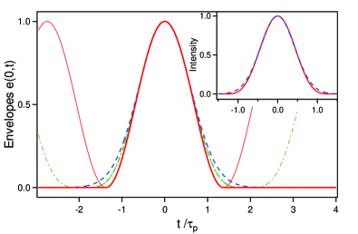
The parameters , and are chosen such that the corresponding intensity profiles (see inset in Fig.1) have the same full width at half-maximum . This is achieved when , and . The duration will be taken as universal time unit in all the following. In this way the profile of the transmitted pulse is entirely determined by the two independent and dimensionless parameters and (more generally the contrast ). As above mentioned the challenge in fast light experiments is to attain significant advance of the pulse maximum compared to the pulse duration. From this viewpoint, a merit factor of the experiments is the fractional advance . Insofar as the envelopes ( ) start at a finite time ( ), it is obvious that the fractional advance obtained with these envelopes will reproduce that obtained with Gaussian pulses if and only if its value is significantly less than , that is for and for . As shown later constitute a sufficient approximation of when whereas the better approximation provided by is necessary for larger fractional advances. We finally mention that, beyond the advantage of a finite duration, both envelopes offer the possibility of a periodic continuation which will be useful to optimise the fractional advance (Sec. V). Except when contrary specified the envelope , leading to simpler calculations, is used in the following.
III SHORT PULSE LIMIT
When the incident pulse is short enough, its spectrum mainly lies in the far wings of the line profile where the medium dispersion is normal bo02 . A delay instead of an advance of the pulse maximum might be expected in such conditions. We show in this section that the opposite occurs. Simple analytical results are obtained when the duration of the incident pulse is short compared to the duration of the pulse reemitted by the medium as considered in the discussion of Eq.(4) that is when re3 . We have then
| (13) |
For an incident pulse of envelope , it is easily shown that
| (14) |
and, according to Eq.(4), the envelope of the transmitted field reads
| (15) |
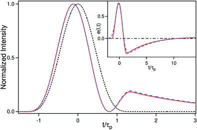
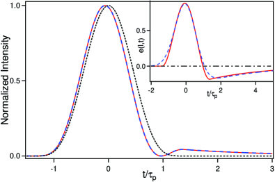
Figures 2 and 3 are respectively obtained for large () and moderate () optical thickness. They show that the intensity profiles determined by Eq.(15) are in perfect agreement with the exact profiles derived by fast Fourier transform (FFT).
Quite generally the fractional advance of the pulse maximum has the approximate form
| (16) |
whereas and thus . This means that, in the short pulse limit, the advance of the pulse maximum will be always much smaller than the group advance. This apparent paradox is explained by the fact that the envelope has a long tail which is essentially negative and artificially increases the advance of its centre of gravity. This tail has the general form
| (17) |
For large optical thickness, it oscillates with successive lobes of rapidly decreasing amplitude and zeroes at the times where designates the corresponding zeroes of . This behaviour is illustrated in the inset of Fig.2. Note that, for the parameters considered, the amplitude of the secondary lobes appearing for (not shown) is very weak, below for the first and largest one. For moderate optical thickness, the decrease of is mainly determined by the term and the tail of the envelope is reduced to a simple exponential of the form as shown in the inset of Fig.3 obtained for . For a five times smaller optical thickness (), the intensity of the tail would be 25 times weaker and the fractional advance of the maximum 5 times smaller. The normalized intensity profile of the transmitted pulse is then nearly undistinguishable from that of the incident pulse although the depth of the dip in the transmission profile is significant ().
Similar calculations can be performed for Gaussian pulses. We only give below the expression of the envelope of the transmitted pulse:
| (18) |
where designates the error function. There is again a perfect agreement with the exact numerical result obtained by FFT. The fractional advance has now the approximate form
| (19) |
The envelopes and are shown in the insets of Fig.2 and Fig.3. As expected, they are quite comparable.
IV LONG PULSE OR ADIABATIC LIMIT
We consider in this section the case opposite to the previous one. We assume that the envelope of the incident pulse is everywhere slowly varying compared to . This implies in particular that the pulse duration is long compared to . The function can then be approximated by where and are, respectively, its area and its centre of gravity. Since is the inverse Fourier transform of , we have and, by an expansion of in cumulants do03 , . Injecting these results in Eq.(4), we get
| (20) |
The envelope of the output field appears equal to that of the input field minus its copy reduced in amplitude and slightly retarded re2 ; ma08 ; cha09 . Assuming that , Eq.(20) takes the form
| (21) |
where the dot designates a time-derivative and where we have taken into account the relations and . In the limit where , we retrieve the classical result
| (22) |
In this limit, the envelope of the output pulse equals that of the input pulse attenuated by the steady state transmission for the field and advanced by (no distortion). It should be however kept in mind that this asymptotic result only holds when and, consequently, that the corresponding fractional delay will be limited.
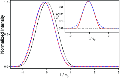
Figure 4 shows an example of situation for which Eq.(22) provides a good approximation of the exact result. It is obtained for and the moderate optical thickness already considered in Fig.3 ( leading to and ) but a much longer pulse duration ( that is ). The fractional advance of the pulse maximum is equal to whereas , actually close to unity.
The asymptotic solution given by Eq.(22) remains acceptable for long pulses even when the condition is poorly satisfied.
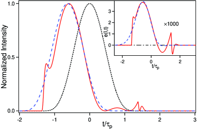
Figure 5 illustrates this point. It is also obtained for but for (). We have now a fractional advance and, despite that the condition of validity of Eq.(22) is far from being fulfilled (), and remain close. A new feature of Fig.5 compared to Fig.4 is the appearance of transients at the beginning (precursor) and the end (postcursor) of the envelope , that is for . They obviously originate in the discontinuity of the second derivative of at the corresponding times, are absent in the case of Gaussian pulses (see inset of Fig.5) and are not taken into account by the adiabatic approximation that assumes that the envelope of the incident pulse is everywhere continuous with continuous derivatives. By a cavalier extrapolation of results obtained in the study of the Sommerfeld precursors ma12 , we have found that the peak amplitude of the precursor roughly scales as
| (23) |
We have numerically checked that this law provides a good estimate of the exact result as soon as the precursor is visible without dominating excessively the main pulse. In the conditions of Fig.5, we get in satisfactory agreement with the amplitude () of the precursor shown in the inset of this figure. The order of magnitude given by Eq.(23) also applies to the postcursor but there is now interference of the postcursor with the tail of the main field and it is then difficult to determine what originates in the postcursor alone.
V OPTIMIZATION OF THE FRACTIONAL PULSE-ADVANCE
The convolution approach used in the previous sections provides both a physical insight on the fast light phenomenon and analytical results in the short and long pulse limits. Unfortunately the corresponding fractional advances may be weak. Larger fractional advances are expected for intermediate pulse durations. The convolution approach can be extended to this case when the optical thickness is moderate, say for . The function appearing in the impulse response may then be approximated by and the convolution product can be explicitly calculated. We will not develop this method here. Indeed more general and simpler results on , can be derived from the envelope of the transmitted field obtained when the envelope of the incident pulse is replaced by its periodic continuation (see the thin lines in Fig.1).
When , its periodic continuation contains only three frequencies (, ). Taking into account that and are complex conjugates, we get
| (24) |
where
| (25) |
The advance of the maximum of on that of is thus
| (26) |
So long as the responses to the successive pulses of do not significantly overlap and as the precursor and postcursor have a negligible amplitude, is expected to be a good approximation of in their common domain of existence. We have then and the fractional advance reads
| (27) |
Equation (26) shows that the advance is the largest and equal to the group advance when , that is for long incident pulses. Unfortunately, it results from Eq.(27) that the corresponding fractional advance is very weak. attains its maximum value when (). The corresponding advance is half of the group advance (). Besides the main pulse is followed by a second one, the relative intensity of which reads
| (28) |
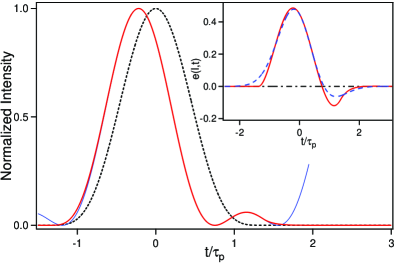
Figure 6 obtained for and , shows that the exact intensity profile is actually quasi-confused with its periodic approximation . and are in perfect agreement with those given by Eq.(27) and Eq.(28), namely and . A simulation (not shown) made for and () evidences that is still a very good approximation of . We get then and , very close to the values and predicted by Eq.(27) and Eq.(28). Note that the relative intensity of the second maximum of intensity is significantly larger than that obtained for .
For large optical thickness, problems arise from the overlapping of the responses to the successive pulses of the periodically continued input envelope and from the precursor and postcursor that can have significant amplitudes. Both problems are solved by replacing considered above by which is a better approximation of the Gaussian pulse. Indeed the successive pulses of are better separated than those of (see Fig.1) and the higher order initial and final discontinuities of ensure negligible amplitude of the precursor and postcursor. reads
| (29) |
It contains five frequencies (, and ) and leads to
| (30) |
The advance of the maximum of is obtained by solving the transcendent equation derived from Eq.(30)
| (31) |
When (), we find that takes its largest value for ().
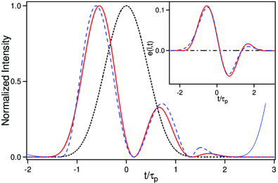
Figure 7, obtained in those conditions, shows that the profile perfectly fits the exact intensity profile with , and a relative intensity of the second maximum . We have added on Fig.7 the profile which would be obtained for the same duration of the incident pulse. For this optical thickness, it does not deviate too strongly from the previous one with , and . The situation dramatically changes for the largest transmission-contrast and optical thickness considered in this article (, ). For , the transmitted pulse is then strongly damaged by the precursor and postcursor and the periodic solution fails to reproduce the exact result (even very approximately). On the other hand, the periodic solution given by Eq.(30) remains a very good approximation of the exact result when .
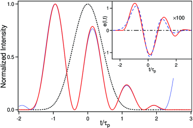
Figure 8 shows the intensity profiles obtained for the pulse duration () leading to the maximum fractional advance with an absolute advance . The only difference between the exact intensity profile and its analytical periodic counterpart lies in the second lobe, the relative intensity () of which is very slightly underestimated in .
A main result of the above study is that the pulse following the main one becomes invading when the transmission contrast increases. For (), there is a range of pulse durations for which the peak intensity of the second pulse exceeds that of the first one. There is then a transition from fast to slow light ta01 ; ta05 ; ko05 ; na09 . When and , this occurs for . For Gaussian incident pulses, the upper limit increases up to and the inset of Fig.8 (obtained for ) shows that the slow light regime is actually attained. We however remark that fast light is always obtained when the pulse duration is sufficiently short or long.
As mentioned in our introduction the main challenge of fast light experiments is to obtain a significant fractional advance with moderate pulse distortion. The first objective is attained in the conditions of Fig.8 but not the latter owing to the presence of large secondary lobes in the intensity profile of the transmitted pulse. In order to reduce their relative intensity to a few percents, the incident pulse should be lengthened and this obviously reduces the fractional advance.
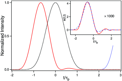
Figure 9 is obtained in the conditions of Fig.8 for instead of . The relative intensity of the second maximum (the fractional advance) then falls to () whereas . Note that the intensity profile of the transmitted pulse is perfectly fitted by the periodic solution . This result is general. As long as the periodic solution works for the pulse duration maximizing the fractional delay, it works better for longer pulses. In particular, the approximation , very good for and (Fig.6), is excellent when and (Fig.4), leading in this latter case to an advance which is exact with four significant figures.
When the intensity of the secondary lobes is weak enough, the distortion of the transmitted pulse mainly consists in a narrowing. This simply results from the negative value of the second cumulant of and the additivity of the cumulants do03 . The narrowing of the pulse originates a difference between the advances at its rise and at its fall. The distortion can then conveniently characterized by the narrowing indicator where the advances and are measured at half-maximum intensity ma03 . In the conditions of Fig.4 [Fig.9], we get [] in agreement with the value derived from Eq.(24) [Eq.(30)].
The procedure of periodic continuation used in this section to maximize the fractional pulse advance can also be used to determine the effect of a detuning of the carrier frequency of the pulses from the resonance frequency . In a frame rotating at , the transfer function reads
| (32) |
where is the detuning. When , we get for the analytical expression
| (33) |
which is reduced to Eq.(30) in the resonant case. The envelope is now complex and the corresponding intensity does not fall to zero in its main part.
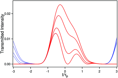
This behavior is illustrated on Fig.10 obtained in the conditions of Fig.7 for , , and (from top to bottom). As expected, the advance (the pulse amplitude) decreases (increases) as a function of the detuning, the fractional advance falling from for to for . Note also the disappearance of the secondary lobes and the strong asymmetry of the transmitted pulse when the detuning exceeds . As expected the analytical periodic solution perfectly fits the response to the pulse of envelope in the whole domain where (). Similar results are obtained when . Taking and , it is in particular possible to reproduce the fractional advance () and the shape (including its asymmetry) of the probe pulse which have been recently evidenced in a four-wave mixing experiment sw17 . Again the intensity profile is very well fitted by the analytical periodic solution. We incidentally mention that, for the same contrast and the same detuning, slow light is obtained for shorter durations of the incident pulse. Otherwise said, a small detuning accelerates the transition from fast to slow light. This phenomenon, easily explained by a spectral analysis, is general and an asymmetry of the absorption line has a comparable effect ta01 ; na09 .
Results obtained on resonance with a symmetric absorption line can be extended to the case where the absorption is exactly compensated by a gain which is also on resonance at the carrier frequency of the incident pulses. The medium is then transparent at this frequency and the transfer function of this twofold resonant medium reads
| (34) |
where and refer to the absorption line as previously and is the ratio of the widths of the absorption and gain lines (). The transmittance actually equals for (transparent medium). It is maximum for , yielding an intensity contrast
| (35) |
For arbitrary , the phase pa87 and the group advance read
| (36) |
| (37) |
In the limit (infinitely broad gain-profile), these expressions are obviously identical to those obtained with a single absorption line. The second form of in Eq.(37) might lead to expect that, for a same contrast , the systems with are more efficient that the reference medium. This is true for the absolute group advance but not for the fractional advance. An examination of the phase as a function of pa87 yields a qualitative explanation of this apparent paradox.
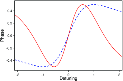
Figure 11, obtained for a same value of when and , shows that the slope at is actually larger for . On the other hand the spectral domain where this slope is positive is narrower and, for a same distortion of the transmitted pulse, the incident pulse should be lengthened to the prejudice of the fractional advance. In fact the maximum fractional advance does not significantly depend on and is even independent of it in the range of validity of the approximation . We then get
| (38) |
is maximum for . This maximum reads
| (39) |
and is actually independent of for a given contrast. Moreover a simulation made for and () leads to a normalized intensity profile that perfectly fits that obtained with a single absorption line for a same contrast, that is for (Fig.6).
VI DISCUSION
In the numerous theoretical articles on fast light published in the last eighteen years, fast light in absorbing media is generally discarded in favor of gain-assisted fast light (renamed superluminal light). We point out on the contrary that, for a same fractional advance and a same distortion of the transmitted pulse, absorbing media are preferable to media with gain. In the most cited experimental report on fast light wa00 , the authors exploit the anomalous dispersion associated with a minimum of gain between two gain lines created by Raman pumping. As remarked in a premonitory article ste94 , the use of an amplifying medium raises some difficulties due in particular to the phenomenon of amplified spontaneous emission and a risk of lasing on the gain lines. Cross modulation instability also limits the gain that can be used ste03b . Another point is that, for a given contrast, the gain-doublet arrangement yields weaker pulse advances than those obtained with a single absorption line ma03 ; ma05 . The fractional advance evidenced in wa00 is actually very small (below ) and, as noted in ri02 , the advances at the rise and at the fall of the pulse are significantly different with a narrowing indicator . Moreover it should be remarked that, contrary to the title given in a subsequent article do01 , the medium is far from being transparent with a transmittance of only and that the experimental results reported in wa00 ; do01 can be reproduced with the single absorption-line arrangement with a transmittance better than . See Fig.1 in ma03 . More convincing experiments using the gain-doublet arrangement are reported in ste03a . The effects of the cross modulation instability ste03b are here overcome by using two separate spatial regions for the two Raman pump beams re4 . The fractional advance is now with a narrowing indicator . We however remark that the same fractional advance can be obtained in the single absorption-line arrangement with a fairly good transmittance () and a weaker pulse narrowing (). See Fig.4.
Independently of the abovementioned reasons that restrict the use of gain media and of eventual problems of detection in the case of absorbing media, one may wonder why fractional advances exceeding with moderate distortion have not been evidenced in linear media. The response is obviously that the large contrasts required to attain this purpose entail a dramatic sensitivity of the transmitted pulse to defects of the incident one. As evidenced in the experiment reported in se85 with , imperceptible quasi-discontinuities of the envelope of the incident pulse or of its derivatives originate transients (wiggles) in the envelope of the transmitted pulse which become invading when is enhanced (even slightly). Simulations also show that the effect of a chirping of the incident pulse may become dramatic for large contrast. Although this point is beyond the scope of the present article (it is a subject per se), it is also probable that the effect of a partial light-incoherence, moderate for small contrast wa02 , will be destructive when this contrast increases.
Compared to other arrangements used to evidence fast light, the single absorption-line arrangement has obviously the advantage of its simplicity, from both experimental and theoretical viewpoints. We however mention that the contrast required to attain a given fractional delay can be slightly reduced by using a doublet of absorption lines ma03 , the experimental implementation of which seems quite feasible. When the lines are separated by , the lowest order contribution to the pulse distortion cancels and the medium transmittance is flattened around . We then get and
| (40) |
In the range of validity of the approximation , the fractional advance reads and attains its maximum for (). We have thus instead of with a single absorption-line. This means in particular that the fractional delay obtained for with a single absorption-line (Fig.6) would be obtained for with a doublet. A simulation shows that the corresponding intensity profiles are very close, both being perfectly fitted by the analytical periodic solution of Eq.(24). Similar results are obtained for large contrasts. An intensity profile comparable to that obtained Fig.9 for with a single absorption-line can be obtained for , both profiles being now well fitted by the analytical periodic solution of Eq.(30).
VII CONCLUSION
The observation of significant fast-light effects requires the use of systems with a large contrast between maximum and minimum transmissions. We have studied in detail the reference case of a dilute medium with a narrow absorption line, the frequency of which coincides with the carrier frequency of the incident pulse. The impulse response relating the envelope of the transmitted pulse to that of the incident pulse is then real. In a retarded time picture (time delayed by the transit time in vacuum), the group advance is positive no matter the propagation distance and can be identified to the advance of the center-of-gravity of over that of . This advance generally differs from the advance of the pulse maximum and, quite generally, a large group advance is not a sufficient condition to observe significant fast light effects.
By convoluting and , fast light appears as resulting from the interference of the incident wave as if it had propagated in vacuum with the wave reemitted by the medium. Explicit analytical expressions of the convolution product are obtained in the short and long pulse limits. In the first case, we get with moderate attenuation of the peak intensity. The experimental evidence of this behaviour seems to be an open challenge. In the second case, tends to and the peak intensity is reduced by the factor . Most experimental results have been obtained in conditions more or less approaching these ones. In both cases the fractional advance is not optimum.
The observation of significant fractional advances leads to use incident pulses of intermediate duration. Analytical results are then obtained by a method of periodic continuation of the incident pulses. When the contrast is below as in most experiments actually performed in optics, the duration maximising has an explicit form and the corresponding advance is half of the group advance . This latter result remains a good approximation when is increased but the main transmitted pulse is then followed by large secondary pulses. Their lowering demands a lengthening of the pulses that reduces below its maximum value.
The range of validity of the method of periodic continuation is very broad. It enables one to reproduce analytically the asymmetry of the transmitted pulses when the carrier frequency of the incident pulses is detuned from resonance. In the case of a resonant transparent medium, it shows that, for a same contrast, the maximum fractional advance is roughly equal to that of our reference medium.
Insofar as the fractional advance is mainly determined by the transmission contrast, the use of amplifying media seems unsuitable to evidence significant fast-light effects. Large gains indeed originate optical instabilities, obviously absent in absorbing media. Anyway, the use of large contrasts requires an exceptional quality of the incident pulse, the smallest imperfections of which can lead to considerable distortion of the transmitted pulse. That is probably the main practical limitation to fast light. Improvement of the quality of the incident pulses combined with the use of a doublet of absorption lines instead of a single line appears to be one way to evidence fast-light effects beyond those observed up to now.
ACKNOWLEDGEMENTS
This work has been partially supported by the Ministère de l’Enseignement Supérieur, de la Recherche et de l’Innovation, the Conseil Régional des Hauts de France and the European Regional Development Fund (ERDF) through the Contrat de Projets État-Région (CPER) 2015–2020, as well as by the Agence Nationale de la Recherche through the LABEX CEMPI project (ANR-11-LABX-0007).
References
- (1) R.Y. Chiao and A.M. Steinberg, Tunnelling times and superluminality, Prog. Opt. 37, 345 (1997).
- (2) R.W. Boyd and D.J. Gauthier, “Slow” and “Fast light”, Prog. Opt. 43, 497 (2002)
- (3) M Tomita, H. Amano, S. Masegi, and A.I. Takluder, Direct Observation of a Pulse Peak Using a Peak-Removed Gaussian Optical Pulse in a Superluminal Medium, Phys. Rev. Lett. 112, 093903 (2014).
- (4) B. Macke, B. Ségard, and F. Wielonsky, Optimal superluminal systems, Phys. Rev. E 72, 035601(R) (2005).
- (5) We use the definitions, sign convention and results of the linear system theory. See, for example, A. Papoulis, The Fourier integral and its applications (Mc Graw Hill, New York, 1987). Note that a different sign convention is often used in optics. The passage from one convention to the other is made by replacing the complex quantities by their conjugates. The phases are then changed in their opposites but the final results obviously do not depend on the used convention.
- (6) L.J. Wang, Causal “all-pass” filters and Kramers-Kronig relations, Opt. Commun. 213, 27 (2002).
- (7) B. Macke and B. Ségard, Comment on: Gain-assisted superluminal light propagation through a Bose-Einstein condensate cavity system, Eur. Phys. J. D 70, 193 (2016).
- (8) D.R. Solli, C.F. McCormik, C. Ropers, J.J. Morehead, R.Y. Chiao, and J.M. Hickmann, Demonstration of Superluminal Effects in an Absorptionless, Nonreflective System, Phys. Rev. Lett. 91, 143906 (2003).
- (9) N. Brunner, V. Scarani, M. Wegmüller, M. Legré, and N. Gisin, Direct Measurement of Superluminal Group Velocity and Signal Velocity in an Optical Fiber, Phys. Rev. Lett. 93, 203902 (2004).
- (10) B. Macke and B. Ségard, Simultaneous slow and fast light involving the Faraday effect, Phys. Rev. A 94, 043801 (2016).
- (11) B. Macke and B. Ségard, Propagation of light-pulses at a negative group-velocity, Eur. Phys. J. D 23, 125 (2003).
- (12) S. Chu and S. Wong, Linear pulse propagation in an absorbing medium, Phys. Rev. Lett. 48, 738 (1982).
- (13) B. Ségard and B. Macke, Observation of negative velocity pulse propagation, Phys. Lett. 109A, 213 (1985).
- (14) H. Tanaka, H. Niwa, K. Hayami, S. Furue, K. Nakayama, T. Kohmoto, M. Kunitomo, and Y. Fukuda, Propagation of optical pulses in a resonantly absorbing medium: Observation of negative velocity in Rb vapour, Phys. Rev. A 68, 053801 (2003).
- (15) J. Keaveney, I.G. Hughes, A. Sargsyan, and C.S. Adams, Maximal refraction and superluminal propagation in a gaseous nanolayer, Phys. Rev. Lett. 109, 233001 (2012).
- (16) S Jennewein, Y.R.P. Sortais, J.F. Greffet, and A. Browaeys, Propagation of light through small clouds of cold interacting atoms, Phys. Rev. A 94, 053828 (2016).
- (17) A.M. Akulshin, A. Cimmino, and G.I. Opat, Negative group velocity of a light pulse in cesium vapour, Quantum Optics 32, 567 (2002).
- (18) A. Godone, F. Levi, and S. Micalizio, Slow light and superluminality in the coherent population trapping maser, Phys. Rev. A 66, 043804 (2002).
- (19) K. Kim, H.S. Moon, C. Lee, S.K. Kim, and J.B. Kim, Observation of arbitrary group velocities of light from superluminal to subluminal on a single atomic transition line, Phys. Rev. A 68, 013810 (2003).
- (20) H. Kang, G. Hernandez, and Y. Zhu, Superluminal and slow light propagation in cold atoms, Phys. Rev. A 70, 011801(R) (2004).
- (21) E.E. Mikhailov, V. Sautenkov, I. Novikova, and G.R. Welch, Large negative and positive delay of optical pulses in coherently prepared dense Rb vapor with buffer gas, Phys. Rev. A 69, 063808 (2004).
- (22) W.G.A. Brown, R. McLean, A. Sidorov, P. Hannaford, and A. Akulshin, Anomalous dispersion and negative group velocity in a coherence-free cold atomic medium, J. Opt. Soc. Am. B, 25, C82 (2008).
- (23) A.M. Akulshin and R.J. McLean, Fast light in atomic media, J. Opt. 12, 104001 (2010).
- (24) L.J. Wang, A. Kuzmich, and A. Dogariu, Gain-assisted superluminal light propagation, Nature (London) 406, 277 (2000).
- (25) M.D. Stenner, D.J. Gauthier, and M. Neifeld, The speed of light in a ‘fast-light’ optical medium, Nature (London) 425, 695 (2003).
- (26) S. Chi, M. Gonzalez-Herraez, and L. Thevenaz, Simple technique to achieve fast light in gain regime using Brillouin scattering, Opt. Express 15, 10814 (2007).
- (27) R.T. Glasser, U. Vogl, and P.D. Lett, Stimulated generation of superluminal light pulses via four-wave mixing, Phys. Rev. Lett. 108, 173902 (2012).
- (28) J.D Swaim and R.T. Glasser, Faster light with competing absorption and gain, Opt. Express 26, 10643 (2018).
- (29) A.M. Steinberg and R.Y Chiao, Dispersionless, highly superluminal propagation in a medium with a gain doublet, Phys. Rev. A 49, 2071 (1994).
- (30) M.D. Stenner and D.J. Gauthier, Pump-beam-instability limits to Raman-gain doublet “fast light” pulse propagation, Phys. Rev. A 67, 063801 (2003).
- (31) M.D. Crisp, Propagation of Small-Area Pulses of Coherent Light through a Resonant Medium, Phys. Rev. A 1, 1604 (1970).
- (32) This result is easily retrieved from the transfer function by means of Laplace transform procedure.
- (33) R. Feynman, R. Leighton, and M. Sands, The Feynman Lectures on Physics, Volume I (Addison-Wesley, Reading 1963), Ch.31.
- (34) See footnote 10 in chi97
- (35) N.S. Bukhman, On the relation between retarded and advanced arrival of a pulse at the output of an optical system, Opt. Spectrosc. 96, 626 (2004).
- (36) B. Macke and B. Ségard, Two-pulse interference and superluminality, Opt. Commun. 281, 12 (2008).
- (37) P. Chamarro-Posada and F.J. Frail-Pelaez, Superluminal propagation in resonant dissipative media, Opt. Commun. 282, 1095 (2009).
- (38) J.C.I. Dooges and J.P. O’Kane, in Deterministic Methods in Systems Hydrology (CRC Press, Boca Raton, 2003), p.52.
- (39) J. Peatross, S.A. Glasgow, and M. Ware, Average Energy Flow of Optical Pulses in Dispersive Media, Phys. Rev. Lett. 84, 2370 (2000).
- (40) A.I. Talukder, Y. Amagishi, and M Tomita; Superluminal to Subluminal Transition in the Pulse propagation in a Resonantly Absorbing Medium, Phys. Rev. Lett. 86, 3546 (2001).
- (41) A.I. Talukder, T. Haruta, and M Tomita, Measurement of Net Group and Reshaping Delays for Optical Pulses in Dispersive Media, Phys. Rev. Lett. 94, 223901 (2005].
- (42) T. Kohmoto, H. Tanaka, S. Furue, K. Nakayama, M. Kunitomo, and Y. Fukuda, Nonadherence to the conventional group velocity for nanosecond light pulses in Rb vapour, Phys. Rev. A 72, 025802 (2005).
- (43) L. Nanda, H. Wanare, and S. Anantha Ramakrishna, Why do superluminal pulses become subluminal once they go far enough?, Phys. Rev. A 79, 041806(R) (2009).
- (44) Whatever is, is a good estimate of the duration of at of its maximum amplitude.
- (45) B. Macke and B. Ségard, Simple asymptotic forms for Sommerfeld and Brillouin precursors, Phys. Rev. A 86, 013837 (2012).
- (46) H.L. Ringmacher and L.R. Mead, Comment on “Gain-assisted Superluminal Light Propagation”, arXiv:physics/0209012 (2002).
- (47) A. Dogariu, A. Kuzmich, and L.J. Wang, Transparent anomalous dispersion and superluminal light-pulse propagation at a negative group delay, Phys. Rev. A 63, 053806 (2001).
- (48) The same strategy of separation of the pumping regions is used in the experiments on an optical fiber reported in chi07 where the pumping is ensured by Brillouin instead of Raman effect.
- (49) L.G. Wang, N.H. Liu, Q. Lin, and S.Y. Zhu, Effect of coherence on the superluminal propagation of light pulses through anomalously dispersive media with gain, Europhys. Lett. 60, 834 (2002)