Scheduling strategies and throughput optimization for the Uplink for IEEE 802.11ax and IEEE 802.11ac based networks
Abstract
The new IEEE 802.11 standard, IEEE 802.11ax, has the challenging goal of serving more Uplink (UL) traffic and users as compared with his predecessor IEEE 802.11ac, enabling consistent and reliable streams of data (average throughput) per station. In this paper we explore several new IEEE 802.11ax UL scheduling mechanisms and compare between the maximum throughputs of unidirectional UDP Multi Users (MU) triadic. The evaluation is conducted based on Multiple-Input-Multiple-Output (MIMO) and Orthogonal Frequency Division Multiple Acceess (OFDMA) transmission multiplexing format in IEEE 802.11ax vs. the CSMA/CA MAC in IEEE 802.11ac in the Single User (SU) and MU modes for 1, 4, 8, 16, 32 and 64 stations scenario in reliable and unreliable channels. The comparison is conducted as a function of the Modulation and Coding Schemes (MCS) in use. In IEEE 802.11ax we consider two new flavors of acknowledgment operation settings, where the maximum acknowledgment windows are 64 or 256 respectively. In SU scenario the throughputs of IEEE 802.11ax are larger than those of IEEE 802.11ac by 64 and 85 in reliable and unreliable channels respectively. In MU-MIMO scenario the throughputs of IEEE 802.11ax are larger than those of IEEE 802.11ac by 263 and 270 in reliable and unreliable channels respectively. Also, as the number of stations increases, the advantage of IEEE 802.11ax in terms of the access delay also increases.
Keywords:IEEE 802.11ax;IEEE 802.11ac; Throughput; Single User; MU-MIMO;OFDMA;
1 Introduction
1.1 Background
The latest IEEE 802.11 Standard (WiFi) [1], created and maintained by the IEEE LAN/MAN Standards Committee (IEEE 802.11), is currently the most effective solution within the range of Wireless Local Area Networks (WLAN). Since its first release in 1997 the standard provides the basis for Wireless network products using the WiFi brand, and has since been improved upon in many ways. One of the main goals of these improvements is to increase the throughput achieved by users and to improve the standard’s Quality-of-Service (QoS) capabilities. To fulfill the promise of increasing IEEE 802.11 performance and QoS capabilities, a new amendment, IEEE 802.11ax ( also known as High Efficiency (HE) ) was recently introduced [2]. IEEE 802.11ax is considered to be the sixth generation of a WLAN in the IEEE 802.11 set of types of WLANs and it is a successor to IEEE 802.11ac [3, 4]. The scope of the IEEE 802.11ax amendment is to define modifications for both the 802.11 PHY and MAC layers that enable at least four-fold improvement in the average throughput per station in densely deployed networks [5, 6, 7, 8]. Currently IEEE 802.11ax project is in a very early stage of development and is due to be publicly released in 2019 .
1.2 Research question
In order to achieve its goals, one of the main challenges of IEEE 802.11ax is to enable simultaneous transmissions by several stations and to enable Quality-of-Service. In this paper we assume that the AP is communicating in a regular fashion with a fix set of stations. We explore some of the UL IEEE 802.11ax new mechanisms given that the AP knows with which stations it communicates and we compare between the unidirectional UDP throughputs of IEEE 802.11ax and IEEE 802.11ac in Single User (SU) and Multi User (MU) modes for 1, 4, 8, 16, 32 and 64 stations scenarios in reliable and unreliable channels. This is one of the aspects to compare between new amendments of the IEEE 802.11 standard [9]. The SU scenario implements sequential transmissions in which a single wireless station sends and receives data at every cycle one at a time, once it or the AP has gained access to the medium. The MU scenarios allow for simultaneous transmission and reception to and from multiple stations both in the Downlink (DL) and UL directions. UL MU refers to simultaneous transmissions, i.e. at the same time, from several stations to the AP over the UL. The existing IEEE 802.11ac standard does not enable UL MU while IEEE 802.11ax enables up to 74 stations to transmit simultaneously over the UL.
The MU transmissions over the UL are done by MIMO and Orthogonal Frequency Divisionn Multiple Access (OFDMA). The IEEE 802.11ax standard expends MIMO transmissions multiplexing format and specifies new ways of multiplexing additional users using OFDMA. The new IEEE 802.11ax OFDMA is backward compatible and enables scheduling different users in different sub-carriers of the same channel. In the IEEE 802.11ac the total channel bandwidth (20 MHz, 40 MHz, 80 MHz etc. ) contains multiple OFDM sub-carriers. However, in IEEE 802.11ax OFDMA, different subsets of sub-carriers in the channel bandwidth can be used by different frame transmissions at the same time. Sub-carriers can be allocated for transmissions in Resource Units (RU) as small as 2 MHz.
Given the above new structure of OFDMA in IEEE 802.11ax, the main contributions of this paper are as follows: First we suggest several scheduling strategies by which a given number of stations can transmit over the UL. Second, we evaluate the throughput and access delay performance of the different scheduling strategies given the different PHY rates of the RUs in the various scheduling strategies, and the different number of RUs in use, which influences the PHY preamble’s length.
1.3 Previous works
Most of the research papers on IEEE 802.11ax so far deal with these challenges and examine different access methods to enable efficient multi user access to random sets of stations. For example, in [10] the authors deal with the introduction of OFDMA into IEEE 802.11ax to enable multi user access. They introduce an OFDMA based multiple access protocol, denoted Orthogonal MAC for 802.11ax (OMAX), to solve synchronization problems and to reduce the overhead associated with using OFDMA. In [11] the authors suggest an access protocol over the UL of an IEEE 802.11ax WLAN based on Multi User Multiple-Input-Multiple-Output (MU-MIMO) and OFDMA PHY. In [12] the authors suggest a centralized medium access protocol for the UL of IEEE 802.11ax in order to efficiently use the transmission resources. In this protocol stations transmit requests for frequency sub-carriers, denoted Resource Units (RU) to the AP over the UL. The AP allocates RUs to the stations which use them later for data transmissions over the UL. In [13] a new method to use OFDMA over the UL is suggested, where MAC Protocol Data Units (MPDU) from the stations are of different lenghs. In [14, 15, 16, 17] a new version of the Carrier Sense Multiple Access with Collision Avoidance (CSMA/CA) protocol, denoted Enhanced CSMA/CA (CSMA/ECA) is suggested, which is suitable for IEEE 802.11ax . A deterministic backoff is used after a successful transmission, and the backoff stage is not reset after service. The backoff stage is reset only when a station does not have any more MPDUs to transmit. CSMA/ECA enables a more efficient use of the channel and enhanced fairness. In [18] the authors assume a network with legacy and IEEE 802.11ax stations and examine fairness issues between the two sets of the stations.
The rest of the paper is organized as follows: In Section 2 we describe the new mechanisms of IEEE 802.11ax relevant to this paper. In Section 3 we describe the transmission scenario with which we compare between IEEE 802.11ax and IEEE 802.11ac in the SU and MU modes. We assume the reader is familiar with the basics of the PHY and MAC layers of IEEE 802.11 described in previous papers, e.g. [19]. In Section 4 we analytically compute the IEEE 802.11ax and IEEE 802.11ac throughputs. In Section 5 we present the throughput of the various protocols and compare between them. Section 6 summarizes the paper. In the rest of the paper we denote IEEE 802.11ac and IEEE 802.11ax by 11ac and 11ax respectively.
2 The new features in IEEE 802.11ax
IEEE 802.11ax focuses on implementing mechanisms to serve more users simultaneously, enabling consistent and reliable streams of data ( average throughput per user ) in the presence of many other users. Therefore there are several new mechanisms in 11ax compared to 11ac both in the PHY and MAC layers. At the PHY layer, 11ax enables larger OFDM FFT sizes, 4X larger, therefore every OFDM symbol is extended from in 11ac to in 11ax. By narrower subcarrier spacing (4X closer) the protocol efficiency is increased because the same Guard Interval (GI) is used both in 11ax and 11ac .
Additionally, to increase the average throughput per user in high-density scenarios, 11ax expends the 11ac Modulation Coding Schemes (MCSs) and adds MCS10 (1024 QAM ) and MCS 11 (024 QAM 5/6), applicable for transmission with bandwidth larger than 20 MHz.
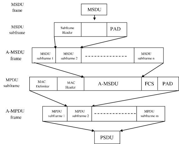
In this paper we focus on UL scheduling methods that enable to optimize the IEEE 802.11 two-level aggregation schemes working point, first introduced in IEEE 802.11n [1, 4], in which several MPDUs can be aggregated to be transmitted in a single PHY Service Data Unit (PSDU). Such aggregated PSDU is denoted Aggregate MAC Protocol Data Unit (A-MPDU) frame. In two-level aggregation every MPDU can contain several MAC Service Data Units (MSDU). MPDUs are separated by an MPDU Delimiter field of 4 bytes and each MPDU contains MAC Header and Frame Control Sequence (FCS) fields. MSDUs within an MPDU are separated by a SubHeader field of 14 bytes. Every MSDU is rounded to an integral multiple of 4 bytes together with the SubHeader field. Every MPDU is also rounded to an integral multiple of 4 bytes.
In 11ax and 11ac the size of an MPDU is limited to 11454 bytes. In 11ac an A-MPDU is limited to 1,048,575 bytes and this limit is extended to 4,194,304 bytes in 11ax. In both 11ac and 11ax the transmission time of the PPDU (PSDU and its preamble) is limited to () due to L-SIG (one of the legacy preamble’s fields) duration limit [1]. The A-MPDU frame structure in two-level aggregation is shown in Figure 1.
IEEE 802.11ax also enables the extension of the acknowledgment mechanism by using a 256 maximum acknowledgment window vs. maximum window of 64 in 11ac. In this paper we also assume that all MPDUs transmitted in an A-MPDU frame are from the same Traffic Stream (TS). In this case up to 256 MPDUs are allowed in an A-MPDU frame of 11ax, while in 11ac up to only 64 MPDUs are allowed.
The acknowledgments are transmitted by special control frames, Block Ack (BAck) and Multi Station BAck, to be specified later.
Finally, in 11ac it is not possible to transmit simultaneously over the UL and only SU is supported. In 11ax this is possible using MU and up to 74 stations can transmit simultaneously.
3 Model
3.1 Transmission patterns
One of the main goals of 11ax is to enable larger throughputs in the network when several stations are transmitting simultaneously over the UL to the AP. In 11ax it is possible to use the MU transmission mode over the UL and up to 74 stations can transmit simultaneously to the AP. On the other hand 11ac does not support the MU transmission mode on the UL, thus when several stations need to transmit they must access the channel one by one, using the CSMA/CA MAC with possible collisions. In this paper we compare between the throughputs received in 11ac and 11ax over the UL when stations, and 64 stations transmit to the AP, which in turn replies with a common MAC acknowledgment frame, BAck or Multi Station BAck to be specified later. In both 11ac and 11ax when only one station is transmitting in the system, this is done by the Single User (SU) mode of transmissions. The station transmits data frames to the AP and receives common broadcast BAck frames in return. In this mode the advantage of the 11ax over 11ac is due to its more efficient PHY layer and its new MCSs. The UL traffic pattern in this case is shown in Figure 2(A) for both 11ac and 11ax.
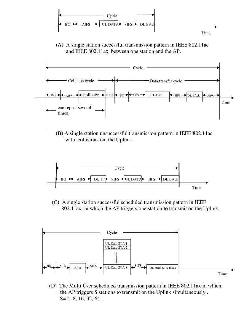
When several stations are transmitting over the UL in 11ac, the air access selection is done by using the CSMA/CA MAC only, which involves collisions between stations, as shown in Figure 2(B). In 11ax such transmissions can be done by either SU (similar to 11ac method) or new UL MU-MIMO modes under control of the AP. The transmission pattern in 11ax using SU is shown in Figure 2(C) which repeats itself times when stations transmit. The AP allocates resources (RU) and solicits the stations to transmit by a spacial control frame, Trigger Frame (TF). Another 11ax MU transmission alternative is to use a combination of UL MU-MIMO and OFDMA in which several stations transmit simultaneously in the same transmission opportunity over the UL. In Figure 2(D) we show this possibility for 11ax where the AP is communicating with stations.
In the case of UL MU the AP allocates the UL Resource Units (RU), i.e. Frequency/Spatial Streams (SS) for transmission of the stations by the before-mentioned TF control frame which is transmitted over the DL to the stations. In the TF, the AP allocates UL RUs and defines the UL transmission format per station. Following the UL transmission the AP acknowledges reception of the data frames by transmitting a common new control frame, Multi Station BAck, to the stations. In this common frame the AP transmits Ack information per station, as a response to the last UL transmission.
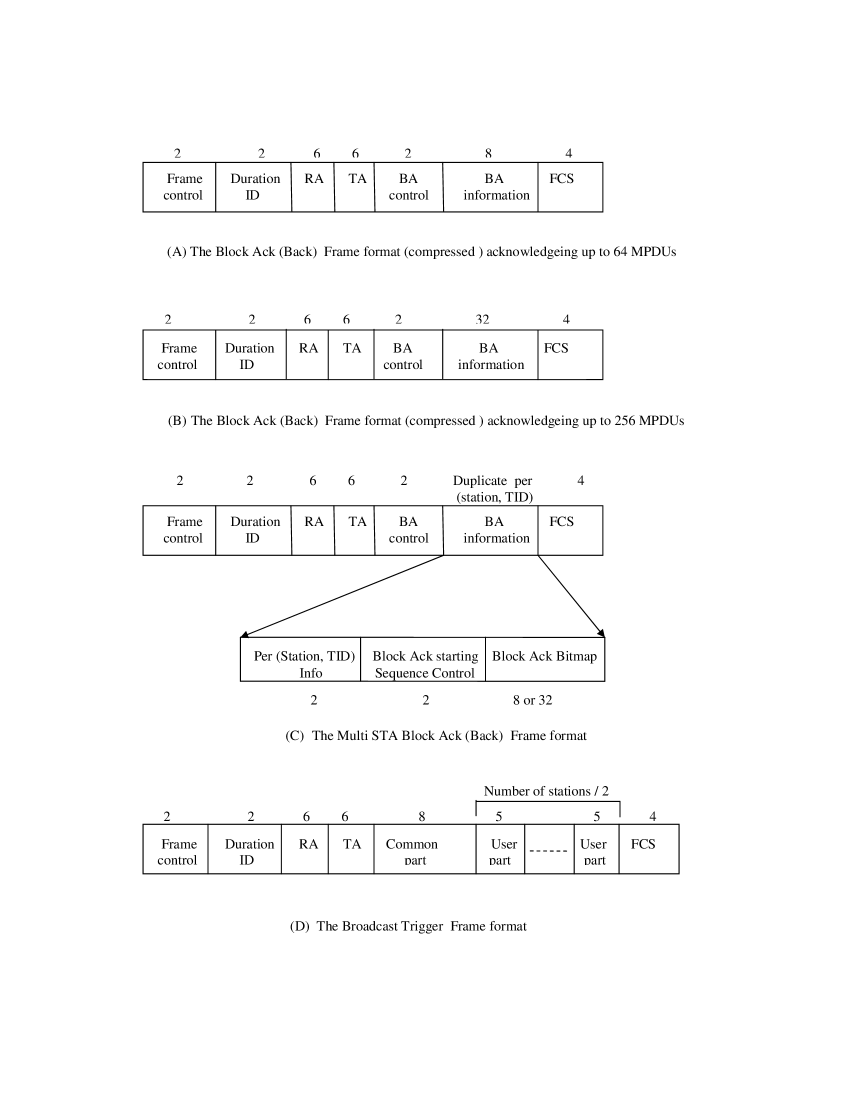
The AP uses the legacy transmission mode when transmitting the BAck, the TF and the Multi Station BAck frames over the DL, both in 11ac and 11ax. The formats of the BAck, Multi Station BAck and TF frames are shown in Figure 3(A), (B), (C) and (D) respectively. The difference between the BAck frames is Figures 3(A) and (B) is that the former acknowledges up to 64 MPDUs while the latter acknowledges up to 256 MPDUs. This format is applicable in 11ax only.
3.2 UL Transmissions’ service scheduling strategies
In 11ax there are several UL scheduling and non-scheduling service strategies for the stations to transmit data to the AP, and we compare between them. Recall that in 11ac the only possible service strategy is to use the CSMA/CA MAC over the UL, as shown in Figure 2(B).
We now specify the UL service scheduling strategies in 11ax for every number of stations, . By we refer to the traffic pattern in Figure 2(A). By we denote a transmission by stations in 11ax using the transmission pattern in Figure 2(C) times in sequence; every transmission is by a different station. By we denote transmissions by stations using the traffic pattern of Figure 2(D) times in sequence; each transmission is by a different group of stations. In this paper and 64.
The UL service scheduling strategies are as follows:
-
•
:
.
-
•
:
, .
-
•
:
, , .
-
•
:
, , , .
-
•
:
, , , , .
-
•
:
, , , , , .
3.3 Channel assignment
We assume the 5GHz band, a 160MHz channel and that the AP and the stations have 4 antennas each. In 11ac every station transmits using 4 SSs. This is because 11ac supports UL SU only and a single station can transmit in all 4 SS if needed. In 11ax a station transmits in SU mode, Figure 2(A) and 2(C), by using 4 SSs and in MU mode by using 1 SS. Recall that in both 11ac and 11ax, and in both SU and MU modes in 11ax, the AP transmits over the DL by using the legacy mode. The DL PHY rate is usually set to the minimum between the UL Data rate and the largest possible PHY rate in the set of the basic rates that is smaller or equal to the UL Data rate. The minimal basic PHY rate is 6Mbps and in the case of UL PHY rates smaller than 6Mbps the DL PHY rate is never less than 6Mbps. This can happen in case of 64 stations (see Table 2).
When using the MU mode in 11ax, the 160MHz channel is divided in the UL into channels of MHz each, . In every such channel 4 stations transmit to the AP, each using 1 SS. For example, for there are 16 channels of 10MHz each; in each of them 4 stations transmit to the AP. When only MU is used. For MU-MIMO+OFDMA is used.
3.4 PPDU formats
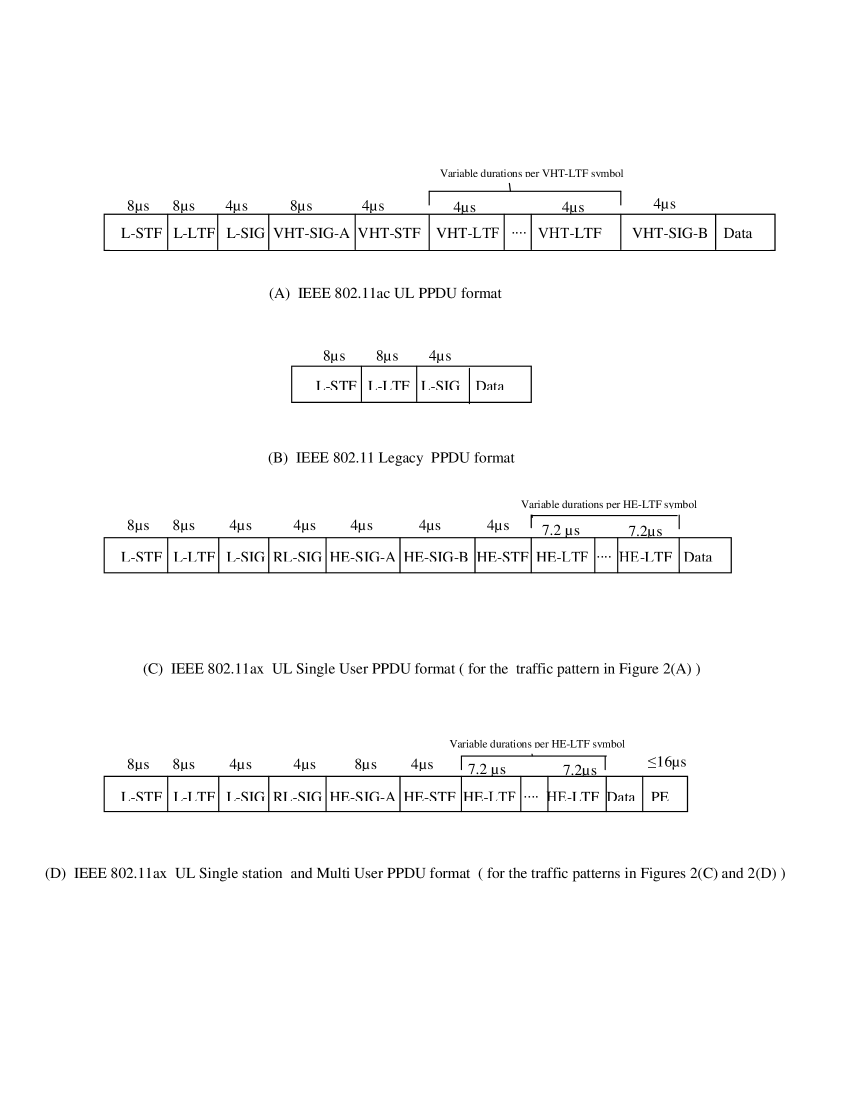
In Figure 4 we show the various PPDUs’ formats in use in the various transmission patterns of Figure 2.
In Figure 4(A) we show the PPDU format used over the UL in the traffic pattern of 11ac , Figures 2(A) and 2(B). In this PPDU format there are the VHT-LTF fields, the number of which equals the number of SSs in use (4 in our case), and each is .
In Figure 4 (B) we show the legacy preamble, used in both 11ac and 11ax over the DL.
In Figure 4 (D) we show the PPDU format used over the UL when a single station transmits in 11ax, Figure 2(C), and UL MU transmission patterns of 11ax , Figure 2(D).
In the 11ax PPDU format there are the HE-LTF fields, the number of which equals the number of SSs in use, 4 in our case. In this paper we assume that each such field is composed of 2X LTF and therefore of duration [2].
Notice also that the PSDU frame in 11ax contains a Packet Extension (PE) field. This field is mainly used in MU mode and we assume that it is in SU and the longest possible in MU, .
3.5 Parameters’ values
In Table 1 we show the PHY rates and the length of the preambles that are used in 11ac and 11ax in SU mode and in the various MCSs. The values are taken from [2].
| 1 | 2 | 3 | 4 | ||||||
| SU UL data | SU UL data | DL BAck transmission | DL BAck transmission | ||||||
| transmission rate in 11ax | transmission rate in 11ac | rate for 11ax | rate for 11ac | ||||||
| PHY Rate | Preamble | PHY Rate | Preamble | PHY Rate | Preamble | PHY Rate | Preamble | ||
| MCS | (Mbps) | () | (Mbps) | () | (Mbps) | () | (Mbps) | () | |
| GI | GI | ||||||||
| 1 station IEEE 802.11 ax | 1 station IEEE 802.11 ac | ||||||||
| 0 | 288.2 | 60.8 | 234.0 | 52.0 | 48.0 | 20.0 | 48.0 | 20.0 | |
| 1 | 576.5 | 60.8 | 468.0 | 52.0 | 48.0 | 20.0 | 48.0 | 20.0 | |
| 2 | 864.7 | 60.8 | 702.5 | 52.0 | 48.0 | 20.0 | 48.0 | 20.0 | |
| 3 | 1152.9 | 60.8 | 936.0 | 52.0 | 48.0 | 20.0 | 48.0 | 20.0 | |
| 4 | 1729.4 | 60.8 | 1404.0 | 52.0 | 48.0 | 20.0 | 48.0 | 20.0 | |
| 5 | 2305.9 | 60.8 | 1872.0 | 52.0 | 48.0 | 20.0 | 48.0 | 20.0 | |
| 6 | 2594.1 | 60.8 | 2106.0 | 52.0 | 48.0 | 20.0 | 48.0 | 20.0 | |
| 7 | 2882.4 | 60.8 | 2340.0 | 52.0 | 48.0 | 20.0 | 48.0 | 20.0 | |
| 8 | 3458.8 | 60.8 | 2808.0 | 52.0 | 48.0 | 20.0 | 48.0 | 20.0 | |
| 9 | 3848.1 | 60.8 | 3120.0 | 52.0 | 48.0 | 20.0 | 48.0 | 20.0 | |
| 10 | 4323.5 | 60.8 | N/A | N/A | 48.0 | 20.0 | N/A | N/A | |
| 11 | 4803.9 | 60.8 | N/A | N/A | 48.0 | 20.0 | N/A | N/A | |
In Table 2 we show the PHY rates and the preambles used in 11ax in MU mode, in the various MCSs and in all cases of the number of stations , i.e. and 64. We also include again the PHY rates of 11ac in SU mode which are also used when stations are transmitting over the UL.
| 1 | 2 | 3 | 4 | ||||||
| MU UL data | SU UL data | DL TF/Multi Station BAck | DL BAck | ||||||
| transmission rate in 11ax | transmission rate in 11ac | transmission rate for 11ax | transmission rate for 11ac | ||||||
| PHY Rate | Preamble | PHY Rate | Preamble | PHY Rate | Preamble | PHY Rate | Preamble | ||
| MCS | (Mbps) | () | (Mbps) | () | (Mbps) | () | (Mbps) | () | |
| GI | GI | GI | GI | ||||||
| 4 stations IEEE 802.11 ax | |||||||||
| 0 | 68.1 | 64.8 | 234.0 | 52.0 | 48.0 | 20.0 | 48.0 | 20.0 | |
| 1 | 136.1 | 64.8 | 468.0 | 52.0 | 48.0 | 20.0 | 48.0 | 20.0 | |
| 2 | 204.2 | 64.8 | 702.0 | 52.0 | 48.0 | 20.0 | 48.0 | 20.0 | |
| 3 | 272.2 | 64.8 | 936.0 | 52.0 | 48.0 | 20.0 | 48.0 | 20.0 | |
| 4 | 408.3 | 64.8 | 1404.0 | 52.0 | 48.0 | 20.0 | 48.0 | 20.0 | |
| 5 | 544.4 | 64.8 | 1872.0 | 52.0 | 48.0 | 20.0 | 48.0 | 20.0 | |
| 6 | 612.5 | 64.8 | 2106.0 | 52.0 | 48.0 | 20.0 | 48.0 | 20.0 | |
| 7 | 680.6 | 64.8 | 2340.0 | 52.0 | 48.0 | 20.0 | 48.0 | 20.0 | |
| 8 | 816.7 | 64.8 | 2808.0 | 52.0 | 48.0 | 20.0 | 48.0 | 20.0 | |
| 9 | 907.4 | 64.8 | 3120.0 | 52.0 | 48.0 | 20.0 | 48.0 | 20.0 | |
| 10 | 1020.8 | 64.8 | N/A | N/A | 48.0 | 20.0 | N/A | N/A | |
| 11 | 1134.2 | 64.8 | N/A | N/A | 48.0 | 20.0 | N/A | N/A | |
| 8 stations IEEE 802.11 ax | |||||||||
| 0 | 34.0 | 64.8 | 234.0 | 52.0 | 36.0 | 20.0 | 48.0 | 20.0 | |
| 1 | 68.1 | 64.8 | 468.0 | 52.0 | 48.0 | 20.0 | 48.0 | 20.0 | |
| 2 | 102.1 | 64.8 | 702.0 | 52.0 | 48.0 | 20.0 | 48.0 | 20.0 | |
| 3 | 136.1 | 64.8 | 936.0 | 52.0 | 48.0 | 20.0 | 48.0 | 20.0 | |
| 4 | 204.2 | 64.8 | 1404.0 | 52.0 | 48.0 | 20.0 | 48.0 | 20.0 | |
| 5 | 272.2 | 64.8 | 1872.0 | 52.0 | 48.0 | 20.0 | 48.0 | 20.0 | |
| 6 | 306.3 | 64.8 | 2106.0 | 52.0 | 48.0 | 20.0 | 48.0 | 20.0 | |
| 7 | 340.3 | 64.8 | 2340.0 | 52.0 | 48.0 | 20.0 | 48.0 | 20.0 | |
| 8 | 408.3 | 64.8 | 2808.0 | 52.0 | 48.0 | 20.0 | 48.0 | 20.0 | |
| 9 | 453.7 | 64.8 | 3120.0 | 52.0 | 48.0 | 20.0 | 48.0 | 20.0 | |
| 10 | 510.4 | 64.8 | N/A | N/A | 48.0 | 20.0 | N/A | N/A | |
| 11 | 567.1 | 64.8 | N/A | N/A | 48.0 | 20.0 | N/A | N/A | |
| 16 stations IEEE 802.11 ax | |||||||||
| 0 | 16.3 | 64.8 | 234.0 | 52.0 | 12.0 | 20.0 | 48.0 | 20.0 | |
| 2 | 48.8 | 64.8 | 702.0 | 52.0 | 24.0 | 20.0 | 48.0 | 20.0 | |
| 3 | 65.0 | 64.8 | 936.0 | 52.0 | 48.0 | 20.0 | 48.0 | 20.0 | |
| 4 | 97.5 | 64.8 | 1404.0 | 52.0 | 48.0 | 20.0 | 48.0 | 20.0 | |
| 5 | 130.0 | 64.8 | 1872.0 | 52.0 | 48.0 | 20.0 | 48.0 | 20.0 | |
| 6 | 146.3 | 64.8 | 2106.0 | 52.0 | 48.0 | 20.0 | 48.0 | 20.0 | |
| 7 | 162.5 | 64.8 | 2340.0 | 52.0 | 48.0 | 20.0 | 48.0 | 20.0 | |
| 8 | 195.0 | 64.8 | 2808.0 | 52.0 | 48.0 | 20.0 | 48.0 | 20.0 | |
| 9 | 216.7 | 64.8 | 3120.0 | 52.0 | 48.0 | 20.0 | 48.0 | 20.0 | |
| 10 | 243.8 | 64.8 | N/A | N/A | 48.0 | 20.0 | N/A | N/A | |
| 11 | 270.8 | 64.8 | N/A | N/A | 48.0 | 20.0 | N/A | N/A | |
| 1 | 2 | 3 | 4 | ||||||
| MU UL data | SU UL data | DL TF/BAck | DL BAck | ||||||
| transmission rate in 11ax | transmission rate in 11ac | transmission rate for 11ax | transmission rate for 11ac | ||||||
| PHY Rate | Preamble | PHY Rate | Preamble | PHY Rate | Preamble | PHY Rate | Preamble | ||
| MCS | (Mbps) | () | (Mbps) | () | (Mbps) | () | (Mbps) | () | |
| GI | GI | GI | GI | ||||||
| 32 stations IEEE 802.11 ax | |||||||||
| 0 | 8.1 | 64.8 | 234.0 | 52.0 | 6.0 | 20.0 | 48.0 | 20.0 | |
| 1 | 16.3 | 64.8 | 468.0 | 52.0 | 12.0 | 20.0 | 48.0 | 20.0 | |
| 2 | 24.4 | 64.8 | 702.0 | 52.0 | 24.0 | 20.0 | 48.0 | 20.0 | |
| 3 | 32.5 | 64.8 | 936.0 | 52.0 | 24.0 | 20.0 | 48.0 | 20.0 | |
| 4 | 48.8 | 64.8 | 1404.0 | 52.0 | 48.0 | 20.0 | 48.0 | 20.0 | |
| 5 | 65.0 | 64.8 | 1872.0 | 52.0 | 48.0 | 20.0 | 48.0 | 20.0 | |
| 6 | 73.1 | 64.8 | 2106.0 | 52.0 | 48.0 | 20.0 | 48.0 | 20.0 | |
| 7 | 81.3 | 64.8 | 2340.0 | 52.0 | 48.0 | 20.0 | 48.0 | 20.0 | |
| 8 | 97.5 | 64.8 | 2808.0 | 52.0 | 48.0 | 20.0 | 48.0 | 20.0 | |
| 9 | 108.3 | 64.8 | 3120.0 | 52.0 | 48.0 | 20.0 | 48.0 | 20.0 | |
| 10 | 121.9 | 64.8 | N/A | N/A | 48.0 | 20.0 | N/A | N/A | |
| 11 | 135.4 | 64.8 | N/A | N/A | 48.0 | 20.0 | N/A | N/A | |
| 64 stations IEEE 802.11 ax | |||||||||
| 0 | 3.5 | 64.8 | 234.0 | 52.0 | 6.0 | 20.0 | 48.0 | 20.0 | |
| 1 | 7.1 | 64.8 | 468.0 | 52.0 | 6.0 | 20.0 | 48.0 | 20.0 | |
| 2 | 10.6 | 64.8 | 702.0 | 52.0 | 9.0 | 20.0 | 48.0 | 20.0 | |
| 3 | 14.2 | 64.8 | 936.0 | 52.0 | 12.0 | 20.0 | 48.0 | 20.0 | |
| 4 | 21.3 | 64.8 | 1404.0 | 52.0 | 18.0 | 20.0 | 48.0 | 20.0 | |
| 5 | 28.3 | 64.8 | 1872.0 | 52.0 | 24.0 | 20.0 | 48.0 | 20.0 | |
| 6 | 31.9 | 64.8 | 2106.0 | 52.0 | 24.0 | 20.0 | 48.0 | 20.0 | |
| 7 | 35.4 | 64.8 | 2340.0 | 52.0 | 24.0 | 20.0 | 48.0 | 20.0 | |
| 8 | 42.5 | 64.8 | 2808.0 | 52.0 | 36.0 | 20.0 | 48.0 | 20.0 | |
| 9 | 47.2 | 64.8 | 3120.0 | 52.0 | 36.0 | 20.0 | 48.0 | 20.0 | |
| 10 | N/A | N/A | N/A | N/A | N/A | N/A | N/A | N/A | |
| 11 | N/A | N/A | N/A | N/A | N/A | N/A | N/A | N/A | |
We assume the Best Effort Access Category in which , and for the transmissions of both the AP and the stations. The BackOff interval is a random number chosen uniformly from the range . In 11ax there are no collisions and since we consider a very ’large’ number of transmissions from the AP, we take the BackOff average value of and the average BackOff interval is which equals for a .
Assuming an OFDM based PHY layer every OFDM symbol in IEEE 802.11ac is . We assume also similar multi-path conditions and therefore set the DL and UL Guard Intervals (GI) to . Thus, in IEEE 802.11ac the duration of a symbol in the DL and UL is . In IEEE 802.11ax the symbol is . In the DL we assume again a GI of and therefore the symbol in this direction is . In the UL MU we assume a GI of and therefore the symbol in this direction is . The UL GI is due to UL arrival time variants. In SU UL the GI is .
Finally, we assume that the MAC Header field is of 28 bytes and the Frame Control Sequence (FCS) field is of 4 bytes. We also consider several channel conditions which are expressed by different values of the Bit Error Rate (BER) which is the probability that a bit arrives corrupted at the destination. We assume a model where these probabilities are bitwise independent [20].
4 Throughput analysis
Let be the number of MPDU frames in an A-MPDU frame, numbered , and be the number of MSDUs in MPDU number . Let MacHeader, MacDelimiter and be the length, in bytes, of the MAC Header, MAC Delimiter and FCS fields respectively, and let . Let be the length, in bytes, of the MSDU frames. Also, let and . is the length, in bits, of MPDU number .
4.1 IEEE 802.11ac
The throughput of 11ac when only one station is transmitting in the network, Figure 2(A), is given by Eq. 1 [19]:
| (1) |
where:
| (2) | |||
and are the transmission times of the data A-MPDU frames and the BAck frames respectively. is based on the BAck frame format given in Figure 3(A) assuming the acknowledgment of 64 MPDUs per A-MPDU frame.
and are the lengths of the OFDM symbols used in the UL and DL respectively and every transmission must be of an integral number of OFDM symbols. The additional 22 bits in the numerators of and are due to the SERVICE and TAIL fields that are added to every transmission by the PHY layer conv. protocol [1]. and are the DL and UL PHY rates respectively and and are the preambles used in the DL and UL respectively, see Figure 4.
Concerning the throughput of 11ac where several stations transmit over the UL, we use the analysis in [21] and verify this analysis by simulation.
4.2 IEEE 802.11ax
The throughput of 11ax for the MU case, i.e. the traffic pattern in Figure 2(D), is given by Eq. 3 [19]:
| (3) |
where:
| (4) | |||
, and are the transmission times of the data A-MPDU frames, the TF frame and the Multi Station BAck frame respectively. is based on the Multi Station BAck frame length given in Figure 3(C) assuming the acknowledgment of 64 MPDUs per A-MPDU frame. When considering the acknowledgment of 256 MPDUs the term 12 in the numerator is replaced by 36. The term in and denotes the number of stations transmitting data simultaneously over the UL.
Notice that by setting in the numerator of Eq. 3 and replacing in the denominator of Eq. 3 by of Eq.2 we receive the throughput of the mode, Figure 2(C). By further deleting the in the denominator of Eq. 3 we receive the throughput of 11ax when only one station is transmitting in the system , Figure 2(A), the same as Eq. 1. Recall that in Eq. 2 assumes the acknowledgment of 64 MPDUs. In 11ax it is also possible to acknowledge 256 MPDUs and in this case the 30 bytes in the numerator of are replaced by 54 bytes, see Figure 3(B).
and are the lengths of the OFDM symbols used in the UL and DL respectively and every transmission must be of an integral number of OFDM symbols. The additional 22 bits in the numerator of , and are due to the SERVICE and TAIL fields that are added to every transmission by the PHY layer conv. protocol [1]. and are the DL and UL PHY rates respectively and and are the preambles used in the DL and UL respectively (see Figure 4).
The terms in Eqs. 1 and 3 are not continuous and so it is difficult to find the optimal X and Y, i.e. the values for X and Y that maximize the throughput. However, in [19] it is shown that if one neglects the rounding in the denominators of Eqs. 1 and 3 then the optimal solution has the property that all the MPDUs contain almost the same number of MSDUs: the difference between the largest and smallest number of MSDUs in MPDUs is at most 1. The difference is indeed 1 if the limit on the transmission time of the PPDU does not enable transmission of the same number of MSDUs in all MPDUs.
We therefore use the result in [19] and look for the maximum throughput as follows: We check for every X, (also for 11ax) and for every Y, , for the received throughput such that is the maximum possible number of MSDUs in an MPDU. All is computed taking into account the upper limit of on the transmission time of the PPDU (PSDU+preamble). In case it is not possible to transmit the same number of MSDUs in all the MPDUs, some of the MPDUs have one more MSDU than the others, up to the above upper limit on transmission time.
The analytical results of 11ax have been verified by an 11ax simulation model running on the simulator [22] and the simulation and analytical results are the same. This outcome is not surprising however, because there is not any stochastic process involved in the scheduled transmissions in 11ax assumed in this paper. Therefore, we do not mention the simulation results any further in this paper.
5 Throughputs’ models and results
5.1 Transmissions’ models and scenarios
We compare between all applicable configurations and scheduling flavors of the stations’ transmissions up to 64 stations. The scheduling flavors are as follows.
Concerning 11ac :
-
•
UL using CSMA/CA . DL Ack transmissions are conducted at the basic rate set.
Concerning 11ax :
-
•
UL one station transmits up to 64 or 256 MPDUs in an A-MPDU frame. DL Ack and TF transmissions are conducted at the basic rate set. When only one station is in the system the AP transmits the BAck control frame only. When there are several stations in the system the AP also transmits the TF control frame. We denote by 11ax/64 and 11ax/256 the cases when a station transmits up to 64 or up to 256 MPDUs per A-MPDU frame respectively.
-
•
UL S= 4, 8, 16, 32 or 64 stations are transmitting in MU. For also OFDMA is used over the UL. Up to 64 MPDUs or 256 MPDUs are transmitted in an A-MPDU frame. DL Ack and TF transmissions are conducted at the basic rate set.
For every number of stations we analyze the optimal working point, i.e. the one that optimizes the throughput, as a function of the transmission scheduling flavor, MCS in use and the A-MPDU frame structure.
First, we checked for every number of stations all of the possible transmission scheduling flavors applicable for this number of stations. For 11ac only CSMA/CA is used over the UL but for 11ax several transmissions scheduling flavors are possible. For example, for 64 stations one can use 64 cycles of Figure 2(C) sequentially i.e. . One can also use 16 cycles of Figure 2(D), namely . Finally, one can also use 8, 4, 2 and 1 cycles of Figure 2(D) denoted before , , and respectively.
Every transmission scheduling flavor is checked over all the applicable MCSs. For 11ac these are MCS0-MCS9. For 11ax these are MCS0-MCS11 except in the case of 64 stations where only MCS0-MCS9 are applicable. We also check for every transmission scheduling flavor and MCS the optimal working point by optimizing the number of MPDUs in A-MPDU frames and the number of MSDUs in every MPDU that yields the maximum throughput, i.e. we look for the optimal A-MPDU frame structure.
We checked all the above for MSDUs of 64, 512 and 1500 bytes and BER.
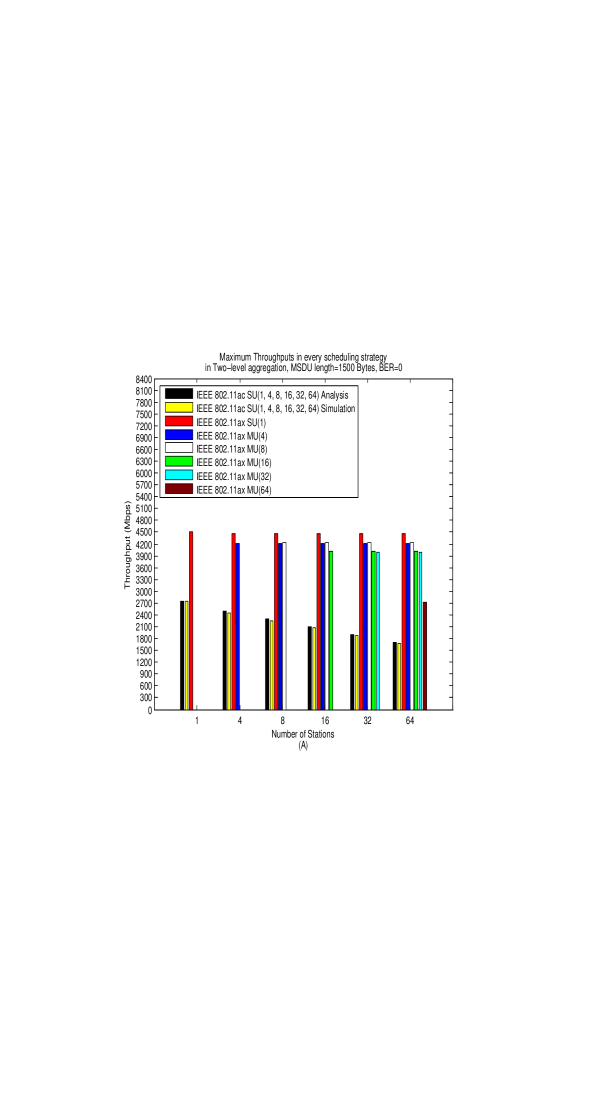
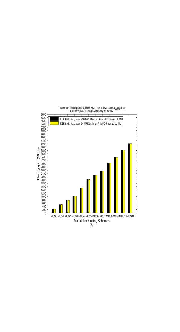
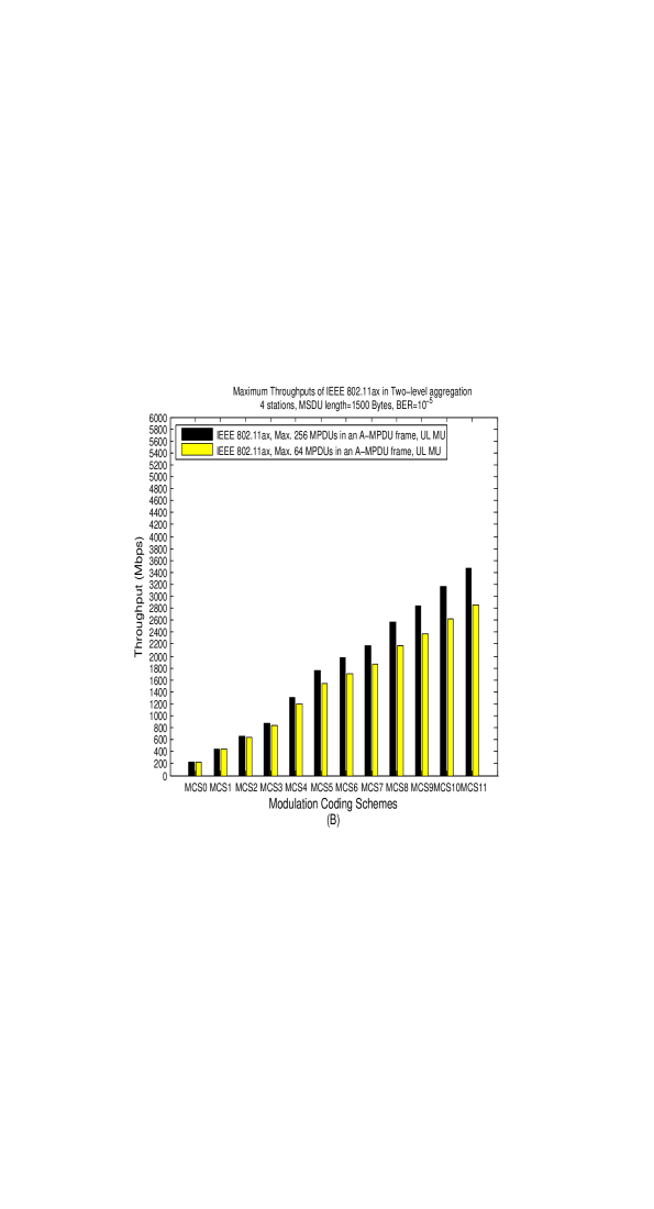
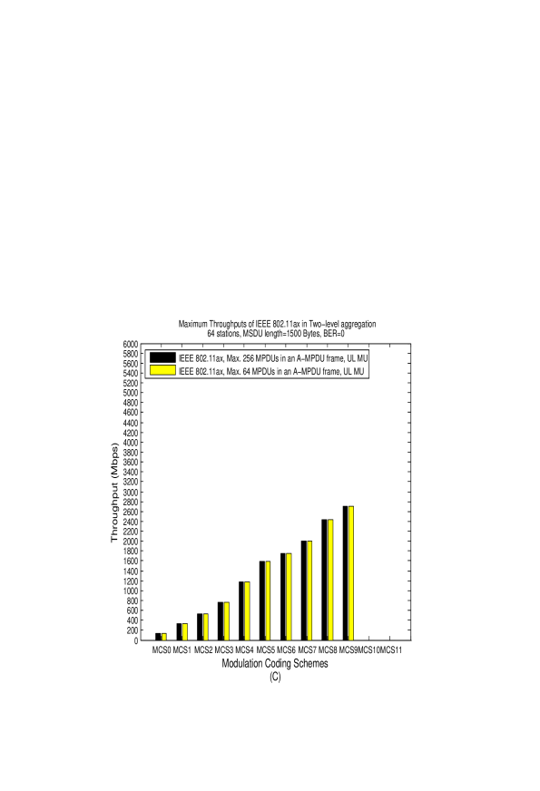
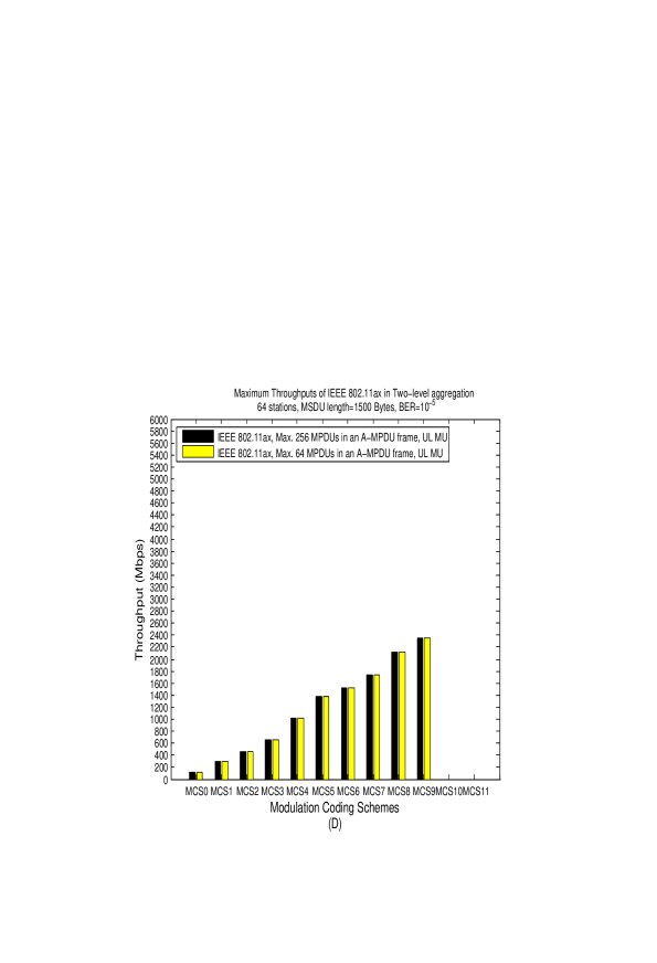
In the next section we show three sets of results. In Figure 5 we show the maximum throughputs received for every number of stations in every transmission scheduling flavor for MSDUs of 1500 bytes. The results for MSDUs of 64 and 512 bytes are similar. In Figure 6 we demonstrate for and the maximum throughputs received in the various MCSs and the influence of the maximum number of MPDUs per A-MPDU frame, 64 or 256, on the received throughput, both for BER0 and BER. Finally, in Figure 7 we show the influence of the number of MPDUs in an A-MPDU frame, from 1 to 256, on the received throughput for the case of and , both for BER0 and BER.
5.2 Throughput results
Recall that in Figure 5 we show the maximum throughputs received as a function of the number of transmitting stations. We show results for MSDUs of 1500 bytes only; similar results are received for MSDUs of 64 and 512 bytes.
For 11ac we show analytical results received from the analysis in [21] and we also verify these results by simulation. For 11ax, when there is only one station in the network we use Figure 2(A) to compute the received throughput. When several stations transmit one at a time, we use the transmission pattern in Figure 2(C) to obtain the results. However, in the legend of all the graphs in Figure 5, these results are shown together under 11ax SU(1).
In Figure 5(A) we show results for BER0. When referring in the legend to e.g. 11ax MU(4) we refer to , i.e. the case in which 4 stations transmit simultaneously to the AP using UL MU, Figure 2(D). When showing results for in the case of e.g. 64 stations, the traffic cycle in Figure 2(D) repeats itself 16 times. In every cycle a different group of 4 stations is transmitting, i.e. .
Note that for 11ac the analytical and simulation results match very closely. For one station in the network, the traffic pattern in Figure 2(A), 11ax has a much larger throughoput than 11ac because in 11ax it is possible to transmit A-MPDU frames of 256 MPDUs, while in 11ac the number of MPDUs per A-MPDU frame is limited to 64. 11ax outperforms 11ac by 64.
We see in Figure 5(A) that the largest throughput is received in . Notice however that the throughput of when only one station is transmitting in the system is larger than the throughput of when stations are transmitting. This is due to the lack of the TF frame when one station transmits, and using the BAck frame which is shorter than the Multi Station BAck. has the largest throughput among all transmission scheduling flavors because of its relatively larger PHY rate - it is larger than 4 times the one in the case of 4 stations, larger than 8 times the one in the case of 8 stations etc.
The throughout of is the same as that of . From Table 2 one can see that the PHY rates in are half of those in . This is balanced by twice the number of stations that are transmitting.
The throughput of is smaller than that of because its PHY rates are less than half those of . The throughput of is less than that in although its PHY rates are half those in due to the transmission time of the TF frame. In the case of 16 stations it is one symbol while in 32 stations it is two symbols.
The throughput of is the smallest because of its very small PHY rates which are much less than half those in . Recall also that MCS10 and MCS11 are not applicable in the case of 64 stations. Also, the transmission of the TF frame now requires 7 symbols.
Finally, 11ax outperforms 11ac by and for 4 and 64 stations respectively because 11ax uses a scheduled transmission pattern while 11ac is based on the contention CSMA/CA MAC protocol access with collisions.
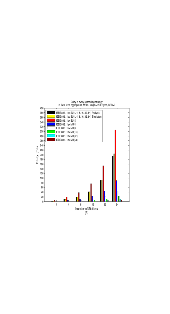
Although the throughput metric is important, the access delay metric is also important. This metric is defined in this paper as the time elapsed between two consecutive transmissions from the same station to the AP.
In Figure 5(B) we show the access delay for the various transmissions’ scheduling flavors. Some applications benefit primarily from lower latency, especially real-time streaming applications such as voice, video conferencing or even video chat. The trade-offs between latency and throughput becomes more complex as applications are scaled out to run in a distributed fashion. The access delay results are as expected; the access delay is lower when more stations transmit simultaneously. It seems that except for the cycles are about the same length in all the transmissions’ scheduling flavors and the relation between the access delays is about the same relation between the number of stations transmitting simultaneously. An exception is the case of where a cycle is shorter, vs. in the other cases and therefore in the case of e.g. 64 stations, the relation between the access delay of and is about 53.
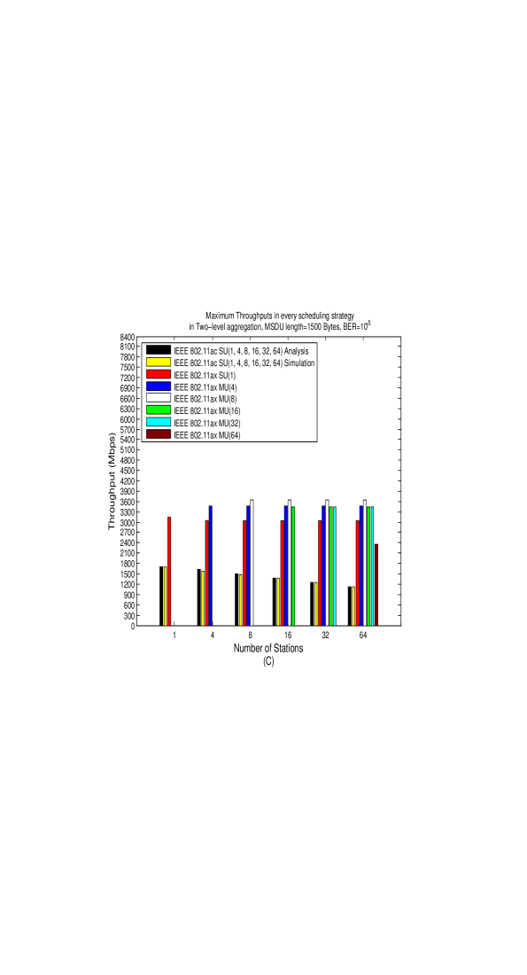
In Figure 5(C) we show the maximum throughput as a function of the number of stations for the case BER. An interesting difference compared to BER0 is that the throughput of is larger than that of . The reason for this phenomena is the relation between the PHY rates in both schemes to the overhead. In BER0 the large PHY rate in causes the overhead as the AIFS and BO to be significant and this leads to large MPDUs in order to achieve a large throughput. On the other hand in BER it is efficient to transmit short MPDUs in order to achieve a large MPDU transmission success probability and therefore to a larger throughput. It turns out that in it is most efficient to transmit MPDUs of two MSDUs but in MPDUs of one MSDU are the most efficient. Overall the larger MPDUs’ success probability in together with the smaller PHY rate makes more efficient.
Notice also that outperforms . This occurs due to its short MPDUs and the smaller PHY rates. The optimal A-MPDU frame structure in is 256 MPDUs of one MSDU each while in it is 242 MPDUs of one MSDU each. In a cycle lasts and in it lasts . In almost twice the number of MSDUs are transmitted than in , but this is done in shorter than twice the cycle length of . This leads to a larger throughput in . The reasons why and have the smallest throughputs are explained earlier as in the case of BER0.
In the case of a single transmitting station 11ax outperforms 11ac by 85. outperforms 11ac by 270.
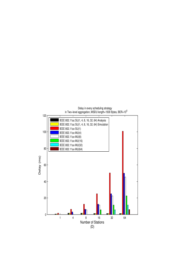
In Figure 5(D) we show the corresponding access delays for the transmissions’ scheduling flavors for BER. Worth mentioning is the relation between the access delays of and . For BER they are close to each other because the maximum throughput in both scheduling flavors is received when A-MPDU frames contain 255 and 242 MPDUs respectively of 1 MSDU each. Since the PHY rates in are half those in , the cycle length in is about double in length as in . However, this is compensated by double the number of stations to which the AP transmits in compared to ; the overall is similar access delays in both scheduling flavors. This situation is different than that of BER0. In BER the cycle length in both and is about the same, around , transmitting as many MSDUs as possible. The limiting factor on the cycle length is the limit on the transmission time of a PPDU. The access delay in is now twice that of because of the 4 vs. 8 transmitting stations in and respectively.
The access delays for BER are smaller than those of BER0 because the MPDUs are shorter, usually containing one MSDU compared to 7 MSDUs in BER0. However, the throughputs are also lower.
In overall and seem to be the best transmission scheduling flavors achieving large throughputs with small access delays.
In Figure 6 we show the throughput performance of and for every MCS, for BER0 and , and for the cases using 64 and 256 MPDUs per A-MPDU frame. In Figures 6(A) and 6(B) we show the results for for BER0 and BER respectively. In Figures 6(C) and 6 (D) the same results respectively are shown for . Notice that for there are no results for MCS10 and MCS11 which are not applicable in this case due to the small PHY rates.
The maximum throughput in is always received in MCS11 ( MCS9 in ) due to the largest PHY rates in this MCS. Considering notice that for BER0 11ax/256 outperforms 11ax/64 only in MCS10 and MCS11 while in BER 11ax/256 outperforms 11ax/64 starting from MCS2. In BER0 it is efficient to transmit large MPDUs. Therefore, the limit on the A-MPDU frame size is imposed by the limit of on the transmission time of the PPDU. Only in larger PHY rates there is room for more than 64 MPDUs and in these cases 11ax/256 has an advantage over 11ax/64 . In BER it is efficient to transmit short MPDUs. In this case the significant limit is the number of MPDUs. 11ax/256 outperforms 11ax/64 from MCS2 because it enables transmitting more short MPDUs than 11ax/64 .
In there is no difference between 11ax/256 and 11ax/64 because the small PHY rates do not enable transmission of more than 64 MPDUs in every MCS, given the limit of the on the transmission time of the PPDU.
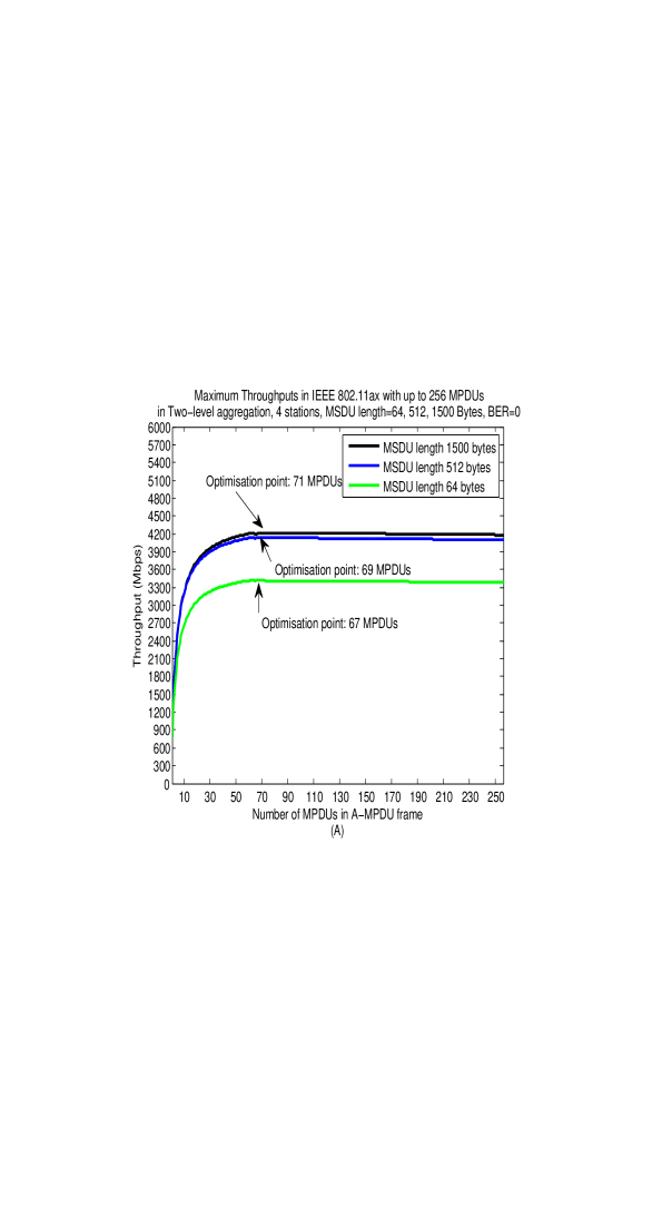
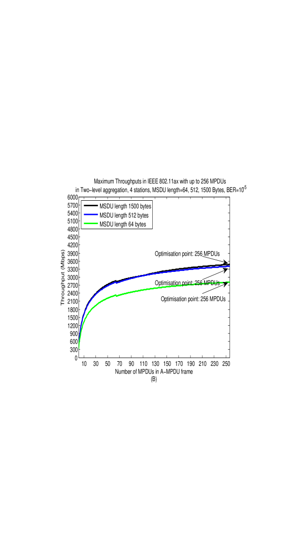
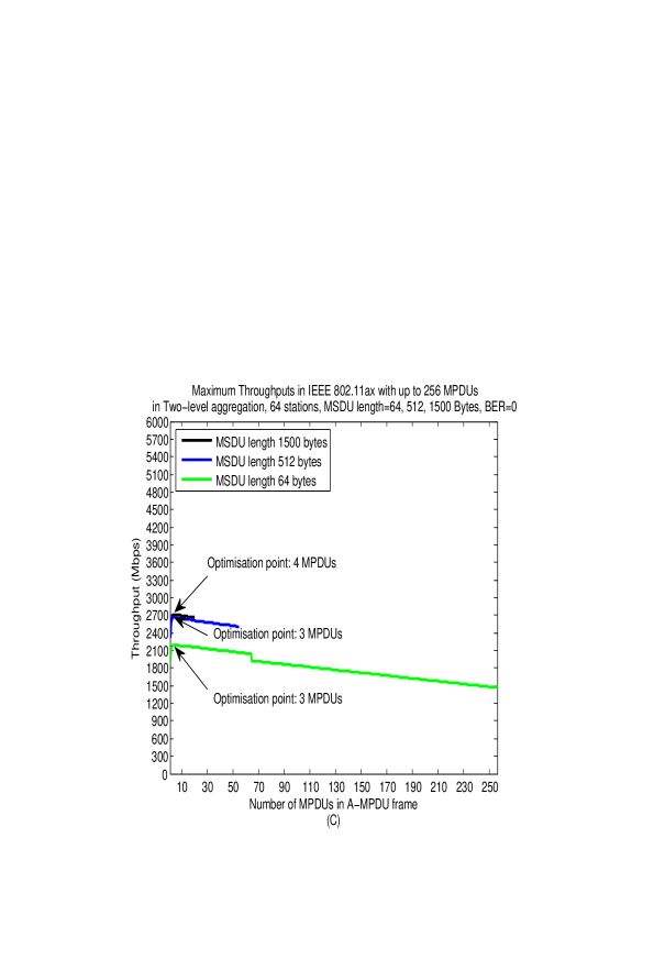
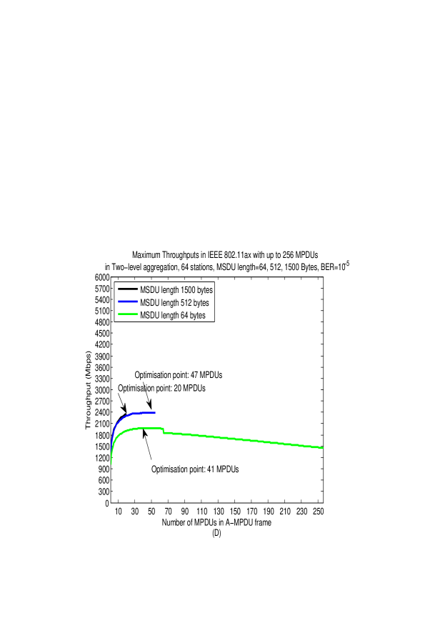
In Figure 7 we show the impact of the number of MPDUs in A-MPDU frames on the received throughput. In Figures 7(A) and 7(B) results are shown for in MCS11, for BER0 and BER respectively. Similar results are shown for for MCS9 in Figures 7(C) and 7(D) respectively. We show results for MSDUs of 64, 512 and 1500 bytes.
Considering and BER0, Figure 7(A), there is an optimal number of MPDUs of around 70 for all the sizes of the MSDUs. In BER0 it is efficient to transmit the largest MPDUs as possible. For about 70 MPDUs all the MPDUs contain the largest possible number of MSDUs and the transmission time is used efficiently. Above 70 MPDUs the limit of on the PPDU transmission time and the MPDUs’ overhead cause a smaller number of MSDUs to be transmitted and the throughput decreases.
In the case of BER, Figure 7(B), the optimal number of MPDUs is 256 since MPDUs are short (to increase the MPDUs’ transmission success probability) and there is enough transmission time for 256 MPDUs in the A-MPDU frame. Every additional MPDU increases the throughput.
In , Figures 7(C) and 7(D), the PHY rates are smaller and the limit on the PPDU transmission time does not enable transmission of many MPDUs with MSDUs of 512 and 1500 bytes. Up to 20 and 55 MPDUs of these sizes can be transmitted respectively, containing one MSDU. For BER0 there is an optimal number of around 3-4 MPDUs that yields the maximum throughput for all MSDUs’ sizes. A larger number of MPDUs decreases the number of MSDUs transmitted due the the MPDUs’ overhead and the throughput decreases. In the case of BER the MPDUs are shorter, and increasing the number of MPDUs increases the throughput since more MSDUs are transmitted. An exception is the case of 64 bytes MSDUs. In this case it is possible to transmit 256 MPDUs and several MSDUs can be transmitted in every MPDU. Increasing the number of MPDUs in this case decreases the number of MSDUs transmitted with a decrease in the throughput.
6 Summary
In this paper we explore multiple scheduling strategies in order to compare between the throughputs of 11ac and 11ax over the Uplink when considering UDP traffic and that several stations are transmitting in the system.
IEEE 802.11ax outperforms 11ac by the order of several tenths of percent mainly due to its scheduling strategies vs. the SU air access based on the CSMA/CA contention method in 11ac . In 11ax the best transmission scheduling flavors are and achieving good results in terms of both throughput and access delay. IEEE 802.11ax achieves its best throughputs in the largest MCS possible, MCS11 for up to 32 stations and MCS9 for 64 stations.
There is an optimal working point for every scheduling strategy in terms of the A-MPDU frame structure. In it is sufficient to transmit around 70 and 256 MPDUs per A-MPDU frame for BER0 and BER respectively. For these numbers of MPDUs are smaller, around 10 and 40 respectively, due to the smaller PHY rates.
Finally, using up to 256 MPDUs in an A-MPDU frame outperforms the use of up to 64 MPDUs in cases when the PHY rates are larger and/or the channel is unreliable, i.e. BER.
References
- [1] IEEE Std. 802.11TM-2016, IEEE Standard for Information Technology - Telecommunications and Information Exchange between Systems - Local and Metropolitan Area Networks - Specific Requirements. Part 11: Wireless LAN Medium Access Control (MAC) and Physical Layer (PHY) Specifications, IEEE, NewYork, December 2016.
- [2] IEEE P802.11axTM/D1.2, IEEE Draft Standard for Information Technology - Telecommunications and Information Exchange between Systems - Local and Metropolitan Area Networks - Specific Requirements. Part 11: Wireless LAN Medium Access Control (MAC) and Physical Layer (PHY) Specific requirements. IEEE, NewYork, 2016.
- [3] IEEE Std. 802.11acTM-2013, IEEE Standard for Information Technology - Telecommunications and Information Exchange between Systems - Local and Metropolitan Area Networks - Specific Requirements. Part 11: Wireless LAN Medium Access Control (MAC) and Physical Layer (PHY) Specific requirements. Amendment 4: Enhancements for Very High Throughput for Operation in Bands below 6 GHz, IEEE, NewYork, 2013).
- [4] Perahia, E. and Stacey, R. (2013) Next Generation Wireless LANs: 802.11n and 802.11ac . 2nd Edition, Cambridge Press, Cambridge.
- [5] Khorov, E., Kiryanov, A. and Lyakhov, A. (2015) IEEE 802.11ax: How to Build High Efficiency WLANs, 2015 International Conference on Engineering and Telecommunication (Ent). Moscow, 18-19 November 2015 14-19.
- [6] Afaqui, M. S., Villegas, E. G. and Aguilera, E. L. (2016) IEEE 802.11ax: Challenges and Requirements for Future High Efficiency WiFi. IEEE Wireless Communications 99, 2-9.
- [7] Deng, D. J., Chen, K. C. and Cheng, R. S. (2014) IEEE 802.11ax: Next Generation Wireless Local Area Networks. 2014 10th International Conference on Heterogeneous Networking for Quality, Security and Robustness (QSHINE), Rhodes, 18-20 August 2014, 77-82. https://doi.org/10.1109/qshine.2014.6928663 .
- [8] Bellalta, B. (2016) IEEE 802.11ax: High-efficiency WLANs. IEEE Wireless Communications, 23, 38-46. https://doi.org/10.1109/MWC.2016.7422404 .
- [9] Karmakar, R., Chattopadhyay, S. and Chakraborty, S. (2017) Impact of IEEE 802.11n/ac PHY/MAC High Throughput Enhancement over Transport/Application layer protocols - A Survey. IEEE Communication surveys and tutorials.
- [10] Qu, Q., Li, B., Yang, M. and Yan, Z. (2015) An OFDMA based Concurrent Multiuser MAC for Upcoming IEEE 802.11ax. IEEE Wireless Communication and Networking Conference Workshops (WCNCW) 2015, 136-141.
- [11] Lin, W., Li, B., Yang, M., Qn, Q., Yan, Z., Zuo, X., and Yang, B. (2016) Integrated Link-System level Simulation Platform for the Next Generation WLAN - IEEE 802.11ax. 2016 IEEE Global Communications Conference (Globecom), 1-7.
- [12] Lee, J., Deng, D. J. and Chen, K. C. OFDMA-based hybrid channel access for IEEE 802.11ax WLAN. unpublished.
- [13] Karaca, M., Bastani, S., Priyanto, B. E., Safavi, M. and Landfeldt, B. (2016) Resource Management for OFDMA based Next Generation 802.11ax WLANs. 2016 9th IFIP Wireless and Mobile Networking Conference (WMNC).
- [14] Jones, V. and Sampath, H. (2015) Emerging technologies for WLAN. IEEE Communication Magazine, 5, 141-9.
- [15] Sanabria-Russo, L., Faridi, A., Bellalta,B., Barcelo, J. and Oliver, M. (2013) Future evolution of CSMA protocols for the IEEE 802.11 standard. 2013 IEEE International Conference on Communication (ICC), 1274-9 .
- [16] Sanabria-Russo, L., Barcelo, J., Faridi, A. and Bellalta, B. (2014) WLANs throughput improvement with CSMA/ECA . 2014 IEEE Conference on Computer Communication Workshops (INFOCOM WKSHPS), 125-6.
- [17] He, Y., Yuan, R., Sun, J. and Gong, W. (2009) Semi-Random Backoff: Towards resource reservation for channel access in wireless LANs. 2009 IEEE International Conference on Network Protocols (ICNP), 21-30.
- [18] Khorov, E., Loginov, V. and Lyakhov, A. (2016) Several EDCA Parameters Sets for Improving Channel Access in IEEE 802.11ax Networks. 2016 International Symposium on Wireless Communication Systems (ISWCS), 419-423.
- [19] Sharon, O. and Alpert, Y. (2014) MAC level Throughput comparison: 802.11ac vs. 802.11n . Physical Communication, 12, 33-49 .
- [20] Lemmon, J. (2002) Wireless link statistical bit error rate model., Technical Report 02-934, U.S. Department of Commerce, June, 2002.
- [21] Chatzimisios, P., Boucouvalas, A. C. and Vitas, V. (2003) IEEE 802.11 Packet Delay - A Finite Retry Limit Analysis. 2003 IEEE Global Communications Conference (Globecom), 950-954.
- [22] ns3 simulator, https://www.nsnam.org