Strong Rashba effect in the localized impurity states of halogen-doped monolayer PtSe2
Abstract
The recent epitaxial growth of 1T-phase of PtSe2 monolayer (ML) has opened a possibility for its novel applications, in particular for spintronics device. However, in contrast to 2H-phase of transition-metal dichalcogenides (TMDs), the absence of spin splitting in the PtSe2 ML may limit the functionality for spintronics application. Through fully-relativistic density-functional theory calculations, we show that large spin splitting can be induced in the PtSe2 ML by introducing a substitutional halogen impurity. Depending on the atomic number () of the halogen dopants, we observe an enhancement of the spin splitting in the localized impurity states (LIS), which is due to the increased contribution of the orbitals coupling. More importantly, we identify very large Rashba splitting in the LIS near Fermi level around the point characterized by hexagonal warping of the Fermi surface. We show that the Rashba splitting can be controlled by adjusting the doping concentration. Therefore, this work paves a possible way to induce the significant Rashba splitting in the two-dimensional TMDs, which is useful for spintronic devices operating at room temperature.
pacs:
Valid PACS appear hereI INTRODUCTION
Recently, spin-orbit coupling (SOC) plays an important role in widely studied systems including topological insulator Hasan and Kane (2010), skyrmions Psaroudaki et al. (2017), and Rashba materials Manchon et al. (2015). When the SOC presences in the crystalline systems with lack of inversion symmetry, an effective magnetic field is generated Rashba (1960); Dresselhaus (1955), leading to various physical effects such as current-induced spin polarization Kuhlen et al. (2012), the spin Hall effect Qi et al. (2006), the spin galvanic effectGanichev et al. (2002), and spin ballistic transport Lu et al. (1998), and thus giving rise to practical spintronics device. Especially the Rashba effect Rashba (1960) attracts considerable attention owing to its electric tunability Nitta et al. (1997a) in a spin field-effect transistor (SFET) Datta and Das (1990), as recently realized experimentally Chuang et al. (2009). However, for spintronics application, materials with strong Rashba SOC are highly desirable since they enable us to allow spintronics device operation at room temperature Yaji et al. (2009).
From this perspective, a new class of materials crystallizing in the two dimensional (2D) structures such as transition metal dichalcogenides (TMDs) monolayer (ML) is particularly appealing due to the strong SOC Zhu et al. (2011); Latzke et al. (2015); Absor et al. (2016, 2017a). The TMDs ML crystallize in a hexagonal structure with stoichiometry, where and are transition metal and chalcogen atoms, respectively. Depending on the chalcogen stacking, two different stable formations of the is achieved in the ground state, namely a phase having a trigonal prismatic hole for metal atoms, and a phase that consists of staggered chalcogen layers forming an octahedral hole for metal atoms Cudazzo et al. (2014). For spintronics application, the ML systems such as molybdenum and tungsten dichalcogenides (MoS2, MoSe2, WS2, and WSe2) have been widely studied Zhu et al. (2011); Latzke et al. (2015); Absor et al. (2016, 2017a). In these systems, the lack of crystal inversion symmetry together with strong SOC in the 5 orbitals of transition metal atoms leads to spin-valley coupling, which is responsible for the appearance of valley-contrasting effects such as valley-selective optical excitations LaMountain et al. (2018), valley Hall response Cazalilla et al. (2014), spin-dependent selection rule for optical transitions Wu et al. (2016), and magneto-electric effect Z.Gong et al. (2013).
Recently, PtSe2 ML, a new member of the 2D TMDs ML with ML structures, has been epitaxially grown successfully on the Pt(111) substrate Wang et al. (2015). This material exhibits the largest electron mobility among the studied TMDs ML Zhang et al. (2014a). In contrast to the ML systems, the crystal structure of the PtSe2 ML is globally centrosymmetric, but, it has strong local dipole field in the two sub-layersYao et al. (2017). Consequently, the SOC induces local Rashba effect exhibiting hidden spin polarizationsZhang et al. (2014b); Razzoli et al. (2017), i.e., the spin-polarized states are degenerated in energy but spatially locked into two sub-layers forming an inversion partner, as recently observed experimentally by Yao et al. using spin- and angle-resolved photoemission spectroscopy (spin-ARPES) Yao et al. (2017). The observed spin-polarized states without the characteristic of the spin splitting in the PtSe2 ML may provide a disadvantage for spintronics device. Therefore, finding a possible way to induces spin splitting in the PtSe2 is crucially important, which is expected to enhance the functionality for spintronics application.
In this paper, by using fully-relativistic density-functional theory (DFT) calculations taking into account the effect of the SOC, we show that large spin splitting can be induced in the PtSe2 ML by introducing a substitutional halogen impurity. We find that depending on the atomic number () of the halogen dopants, enhancement of the spin splitting is achieved in the localized impurity states (LIS), which is due to the increased contribution of the orbitals coupling. More importantly, we identify very large Rashba splitting in the LIS near Fermi level around the point characterized by hexagonal warping of the Fermi surface. We show that this Rashba splitting can be controlled by adjusting the doping concentration. Finally, a possible application of the present system for spintronics will be discussed.
II Model and Computational Details
To investigate the effect of an impurity on the electronic properties of the PtSe2 ML, we performed first-principles electronic structure calculations based on the density functional theory (DFT) within the generalized gradient approximation (GGA) Perdew et al. (1996) using the OpenMX code Ozaki et al. (2009). We used norm-conserving pseudopotentials Troullier and Martins (1991), and the wave functions are expanded by the linear combination of multiple pseudoatomic orbitals (LCPAOs) generated using a confinement scheme Ozaki (2003); Ozaki and Kino (2004). In the case of the pristine PtSe2 ML, the atomic orbitals are specified by Pt7.0- and Se9.0-, which means that the cutoff radii are 7.0 and 9.0 Bohr for the Pt and Se atoms, respectively, in the confinement scheme Ozaki (2003); Ozaki and Kino (2004). For the Pt atom, two primitive orbitals expand the , , and orbitals, while, for the Se atom, two primitive orbitals expand the and orbitals, and one primitive orbital expands orbital. The impurity is taken from the halogen family such as F, Cl, Br, and I atoms. Similar to the Se atom, two primitive orbitals expand the and orbitals, and one primitive orbital expands orbital for the halogen atoms. The effect of the SOC was included in our DFT calculations.
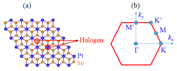
To model the PtSe2 ML, we used a periodic slab model with a sufficiently large vacuum layer (20 Å). Next, we construct a 4x4x1 supercell of the PtSe2 ML to model the impurity system. We then introduce a substitutional halogen impurity in the PtSe2 ML where two different cases are considered: (i) the impurity is located on the Se site and (ii) Pt site [Fig. 1(a)]. The larger supercells (5x5x1 and 6x6x1 supercells) are used to test our calculational results, and we confirmed that it does not affect the main conclusion. The geometries were fully relaxed until the force acting on each atom was less than 1 meV/Å. To confirm the stability of the impurity, we calculated formation energy of a particular substitutional dopant defined as:
| (1) |
where is the total energy of the halogen doped PtSe2 ML, is the total energy of the pristin PtSe2 ML, while and are the chemical potential of the substitutional halogen atom and the substituted Se (Pt) host atoms, respectively. Here, both and obtain the following requirements:
| (2) |
| (3) |
Under Se-rich condition, is the energy of the Se atom in the bulk phase (hexagonal Se, ) which corresponds to the lower limit on Pt, . On the other hand, in the case of the Pt-rich condition, is associated with the energy of the Pt atom in the bulk phase (fcc Pt, ) corresponding to the lower limit on Se, .
III RESULT AND DISCUSSION
Before we discuss the effect of a halogen impurity on the electronic properties of the PtSe2 ML, we examine structural and energetic stability. The PtSe2 ML belongs to a structure () with space group. However, it has a polar group and a centrosymmetric group for the Se and Pt sites, respectively. Here, one transition metal atom (or chalcogen atom) is located on top of another transition metal atom (or chalcogen atom) forming octahedral coordination, while it shows trigonal structure when projected to the (001) plane [Fig. 1(a)]. We find that the calculated lattice constant of the PtSe2 ML is 3.75 Å, which is in good agreement with the experiment (3.73 ÅWang et al. (2015)) and previous theoretical calculations (3.75 ÅZhuang and Hennig (2013); Zulfiqar et al. (2016)).
| Model | Bond lenth | (Se-rich) | (Pt-rich) | |
|---|---|---|---|---|
| Pure | 2.548 | |||
| Doping in Se sites | ||||
| F doping | 2.402 | -5.87 | -5.52 | |
| Cl doping | 2.615 | -4.11 | -3.76 | |
| Br doping | 2.715 | -3.11 | -2.77 | |
| I doping | 2.843 | -1.13 | -0.78 | |
| Doping in Pt sites | ||||
| F doping | 2.652 | 0.19 | 0.56 | |
| Cl doping | 2.681 | 0.05 | 0.42 | |
| Br doping | 2.797 | -0.07 | 0.30 | |
| I doping | 2.893 | -0.33 | 0.04 |
When a halogen impurity is introduced, the position of the atoms around the impurity site is substantially relaxed from the pristine atomic positions. To examine the optimized structure of the impurity systems, we show the calculated results of halogen-Pt and halogen-Se bond lengths (,) in Table I. In the case of the impurity on the Se site, three Pt atoms surrounding the impurity site are found to be relaxed. Consequently, the bond length becomes smaller or larger than in the pristine system depending on the halogen atoms. For instant, in the case of F doping, (2.402 Å) is smaller than (2.548 Å) in the pristine system. However, for the case of Cl, Br, and I dopings, (2.615 Å, 2.715 Å, and 2.843 Å, respectively) are larger than in the pristine system. Since at each hexagonal side has the same value, trigonal symmetry suppresses the impurity to exhibit the point group, which is similar to those observed on the halogen-doped WS2 Guo et al. (2017) ML and Se vacancy of PtSe2 ML Absor et al. (2017b). Similarly, the impurity on the Pt site also induces atomic relaxation so that the six Se atoms are significantly moved away from each other. Therefore, is larger than in the pristine system [see Table 1]. However, three-fold rotation preserves around the impurity site. Thus the symmetry of the system retains the point group.
The significant structural changes induced by a halogen impurity is expected to strongly affect the stability of the PtSe2 ML, which is confirmed by the calculated result of the formation energy () as given in Table I. We find that of the impurity on the Se site is much lower than that on the Pt site, indicating that the formation of the impurity on the Se site is more favorable. Moreover, the calculated value of under the Se-rich condition is smaller than that under the Pt-rich condition, showing that the doped compounds under Se-rich can be realized in the equilibrium condition. Furthermore, for the larger element of the halogen atoms, the formation of the impurity is stabilized by enlarging the bond length . Therefore, increases from F to I doping systems, which is consistent with that observed on MoS2 Dolui et al. (2013) and WS2 Guo et al. (2017) MLs.
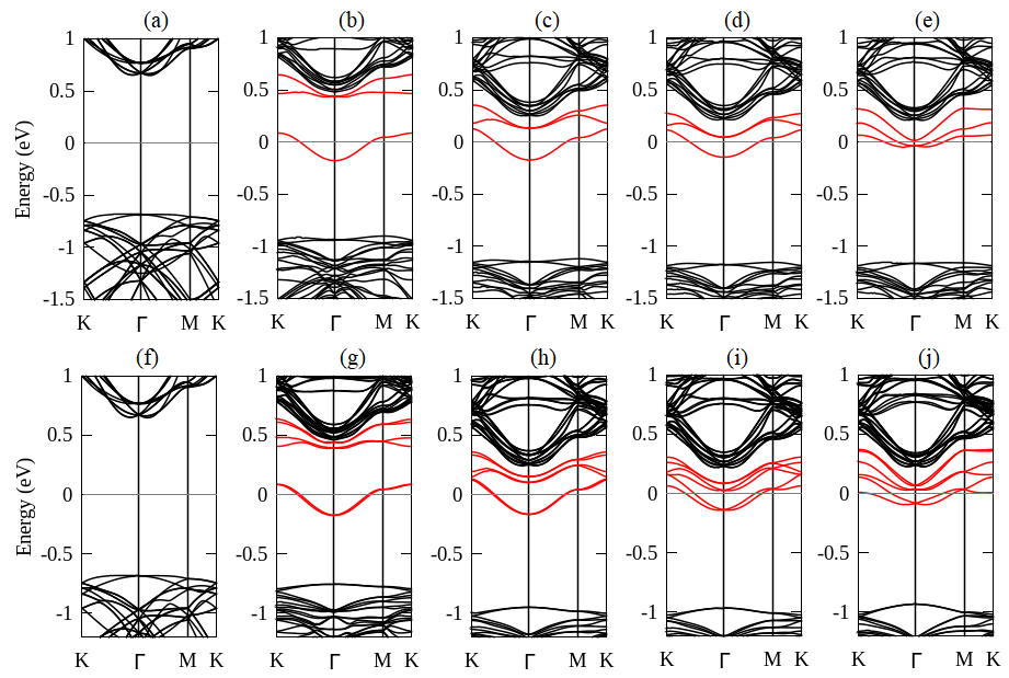
Strong modification of electronic properties of the PtSe2 ML is expected to be achieved by introducing a halogen impurity. Here, we focused on the impurity on the Se site since it has lower formation energy than that on the Pt site. Figure 2 shows electronic band structures of the impurity systems compared with those of the pristine one. In contrast to the pristine system [Figs. 2(a) and 2(f)], we identify localized impurity states (LIS) in the band structures of the impurity systems, which are located close to the conduction band minimum (CBM) [Figs. 2(b)-2(e)]. More importantly, we find spin-split bands at the LIS [Figs. 2(g)-2(j)] when the SOC is taken into account. Depending on the number of the halogen dopants, enhancement of the spin splitting in the localized impurity states (LIS) is observed for the larger element, indicating that these systems are promising for spintronics application.
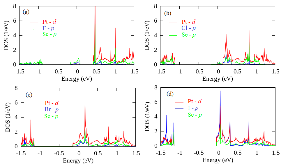
To clarify the origin of the spin-split bands in the LIS, we show in Fig. 3 the calculated results of the density of states (DOS) projected to the atomic orbitals. In the atomic representation, coupling between atomic orbitals will contributes to the non-zero SOC matrix element through relation , where is angular momentum resolved atomic SOC strength with , and are the orbital angular momentum and Pauli spin operators, and is the atomic orbitals. Accordingly, the orbitals hybridization play an important role in inducing the spin splitting. From the calculated results of the DOS, it is found that different orbitals hybridization in the LIS is observed under different impurity systems. In the case of the F and Cl dopings, we find that the LIS is dominated by coupling between the halogen- and the nearest-neighbor Se- orbitals, while the contribution of the Pt- orbital is small [Figs. 3(a) and 3(b)]. As a result, the SOC matrix element contributes only minimally to the spin splitting [Figs. 2(g) and 2(h)]. However, strong coupling between Pt-, Se-, and halogen- orbitals is achieved in the LIS of the Br and I dopings [Figs. 3(c) and 3(d)], which is responsible for inducing the large spin splitting in the LIS as shown in Figs. 2(g)-2(j). It is noted here that in all of the impurity systems, the Pt- orbital is dominant in the CBM. This is, in fact, consistent with the calculated DOS on the pristine system where the Pt- orbital plays a significant role in characterizing the CBM as shown in Fig. S1 in the supplemental materialSup .
To further analyze the spin-split bands in the LIS, we discuss our systems in term of symmetry argument. Here, the LIS can be identified according to the group of the wave vector (GWV) at high-symmetry points in the Brillouin zone (BZ). Similar to the space group of the real space, the GWV belongs to at the point. Therefore, the absence of the SOC leads to the fact that the LIS are decomposed into singlet and doublet characterized by and of the single-group irreducible representations (IRs), respectively. However, away from the point, lowering symmetry of the GWV is achieved, which is expected to induce splitting bands. Taking the point as an example, the point group of the GWV becomes . Here, at the point transforms into at the point, while at the point splits into and at the point [See Fig. S2 (a) in the supplementl material Sup ]. Introducing the SOC, the spin-split bands of the LIS are established according to double-group IRs of the GWV. The double group IRs are evaluated by the direct product between single group () and spin representation () through the relation . At the point, the direct product leads to the fact that transforms into , while splits into , , and . On the other hand, at the point, splits into and , while and splits into and , respectively. The classification of the double-group IRs in the energy band at the and points is given in Fig. S2 (b) in the supplemental material Sup .
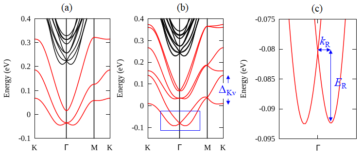
Next, we focused on the spin-split bands of the LIS near Fermi level. Here, we choose the I doping as a representative of halogen impurity systems because of the enhanced spin splitting. The band structures near the Fermi level calculated without and with the SOC are shown in Figs. 4(a) and 4(b), respectively. We find that besides a large valley splitting ( meV) at the point, we also observed the obvious Rashba splitting around the point [Fig. 4(b)]. To quantify the strength of the Rashba splitting (), we show in Fig. 4(c) the highlighted spin-split bands characterized by the Rashba energy () and momentum offset (). Here, and are important to stabilize spin precession and achieve a phase offset for different spin channels in the spin-field effect transistor device . We summarize the calculated results of the parameters , , and in Table II, and compare these results with a few selected systems from previously reported calculations. It is found that the calculated value of in the case of the I doping is 1.7 eVÅ, which is the largest among the halogen impurity systems. Moreover, the in the case of the I doping is much larger than that of the conventional semiconductor heterostructures InGaAs/InAlAs Nitta et al. (1997b), the oxide interface LaAlO3/SrTiO3 Zhong et al. (2013), surface Au(111) LaShell et al. (1996), and Bi(111)Koroteev et al. (2004). Even, this value is comparable with the bulk BiTeBr Sakano et al. (2013), BiTeCl Xiang et al. (2015), GeTe Di Sante et al. (2013), and SnTe Plekhanov et al. (2014), and newly reported 2D materials including LaOBiS2 Liu et al. (2013), and BiSb Singh and Romero (2017).
| Systems | Reference | |||
| I doping | 0.015 | 12.5 | 1.7 | This work |
| Br doping | 4.91 | 1.07 | This work | |
| Cl doping | This work | |||
| F doping | This work | |||
| Surface | ||||
| Au (111) surface | 0.012 | 2.1 | 0.33 | Ref.LaShell et al. (1996) |
| Bi (111) surface | 0.05 | 14 | 0.55 | Ref.Koroteev et al. (2004) |
| Interface | ||||
| InGaAs/InAlAs | 0.028 | 0.07 | Ref.Nitta et al. (1997b) | |
| LaAlO3/SrTiO3 | 0.01 to 0.05 | Ref.Zhong et al. (2013) | ||
| Bulk | ||||
| BiTeCl2 | 0.03 | 18.45 | 1.2 | Ref.Xiang et al. (2015) |
| BiTeBr2 | Ref.Sakano et al. (2013) | |||
| GeTe | 0.09 | 227 | 4.8 | Ref.Di Sante et al. (2013) |
| SnTe | 0.08 | 272 | 6.8 | Ref.Plekhanov et al. (2014) |
| 2D ML | ||||
| LaOBiS2 | 0.025 | 38 | 3.04 | Ref.Liu et al. (2013) |
| BiSb ML | 0.0113 | 13 | 2.3 | Ref.Singh and Romero (2017) |
It is noted here that the calculated results of shown in Table II are obtained from the linear Rashba model where energy band dispersion is written as . Here, is expressed as , and is the electron effective mass. However, for the accuracy of , we should take into account the higher order correction of in the Rashba Hamiltonian . Since the impurity systems have symmetry, the total Hamiltonian can be expressed as kinetic part and the Rashba part up to third order correction of as Vajna et al. (2012); Absor et al. (2017b, 2018)
| (4) |
where , is the azimuth angle of momentum with respect to the axis along the -K direction, and are Pauli matrices. In Eq. (4), the parameters and characterize in-plane spin polarizations, while is the warping parameters contributing to the out-of-plane component of spin polarizations. Solving the eigenvalues problem involving Hamiltonian of Eq. (4), we obtain the spin splitting energy () expressed in the square form as follow:
| (5) |
The parameters , , and can be calculated by numerically fitting of Eq. (5) to the spin splitting energy along the -K and -M directions obtained from our DFT calculations, and we find that =1.68 eVÅ, =-9.8 eVÅ3, and eVÅ3. We noted here that the calculated values of obtained from the higher order correction is fairly agreement with that obtained from the linear Rashba model. However, the large value of and found in the presence system indicates that the contribution of the higher order correction of the in the to the spin-splitting properties of the LIS is significant, in particular for the spin splitting at higher energy level and large wave vector .
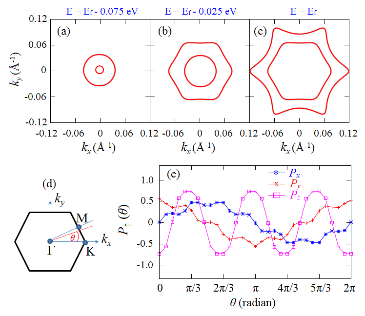
To further confirm the significant higher order correction of to the spin splitting in the LIS, we show a set of a constant energy contour corresponding to the spin-polarized states in the LIS around the point near the Fermi level as given in Fig. 5. We find that the shape of constant energy contour has strong energy dependence [Figs. 5(a)-5(c)]. Close to degenerate states around the point, we observed circle shape of the energy contour [Fig. 5(a)], but the shape becomes hexagonal at higher energy level [Fig. 5(b)]. Interestingly, we identify the hexagonal warping character of the energy contour at Fermi level [Fig. 5(c)], exhibiting anisotropic Fermi surface. The evolution of the energy contour concerning the energy is similar to those observed on the surface states of Bi2Te3 surface Fu (2009). Moreover, by investigating angle-dependent of the spin polarization ( in the -space [Fig. 5(d)], we identify significant out-of-plane spin components () in the Fermi surface along the -K direction. Here, we find three-fold symmetry of with up and down spin alternations [Fig. 5(e)], which is consistent with the term in the Eq. (4). On the other hand, according to the first term of the in the Eq. (4), the in-plane spin components (, ) retains along the -M direction, inducing helical characters of the spin polarizations [Fig. 5(e)]. Remarkably, the observed out-of-plane spin polarizations together with the helical character of the in-plane spin polarizations in the present system play an important role for controlling the spin precession Altmann et al. (2016); Kunihashi et al. (2017), which is significant for generating spin-polarized currents in the spintronics device.
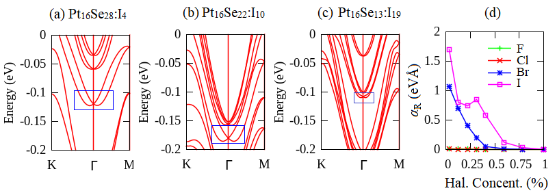
Next, we discuss the properties of the Rashba splitting in the impurity systems by considering the effect of the doping concentration. Similar to the case of single doping, the Rashba splitting is also visible in the case of multiple dopings, which is observed in the LIS near Fermi level around the point [Figs. 6(a)-(6c)]. We also find that the Rashba splitting tends to reduce as the doping concentration enhances, which is, in fact, consistent with decreasing the Rashba spin-orbit strength shown in Fig. 6(d). Therefore, the Rashba splitting in the impurity systems can be controlled by adjusting the doping concentration. It is expected that the zero (or very small) Rashba splitting can be achieved when the Se atom in the PtSe2 ML is fully replaced by the halogen atoms. Here, a new Pt structure, where is the halogen atom, is achieved, leading to the fact that the symmetry of the system returns to the centrosymmetric group of . When the Rashba splitting is extremely small, we can achieve a very long spin coherence. Thus this system can be used as an efficient spintronics device.
Thus far, we have found that the large Rashba spin splitting is achieved on the halogen-doped PtSe2 ML. Because the Rashba spin splitting is achieved on the LIS near Fermi level [Fig. 3(c)], -type doping for spintronics is expected to be realized. Therefore, it enables us to allow operation as a spin-field effect transistor device at room temperature Yaji et al. (2009); Yan et al. (2016); Danker and Dash (2017). We expect that our method for inducing and controlling the large Rashba splitting by using the halogen impurity can also be achieved on other 2D TMDs ML having ML systems such as the other platinum dichalcogenides (PtS2, PtTe2) Manchanda et al. (2016), vanadium dichalcogenide (VS2, VSe2, VTe2) Cudazzo et al. (2014), stanium dichalcogenide (SnS2, SnSe2Gonzalez and Oleynik (2016), and rhenium dichalcogenides (ReS2, ReSe2, ReTe2) Horzum et al. (2014) where the structural, symmetry, and electronic properties are similar. Therefore, this work provides a possible way to induce the large Rashba spin splitting in the 2D nanomaterials, which is very promising for future spintronics application.
IV CONCLUSION
We have investigated the effect of a substitutional halogen impurity on the electronic properties of the PtSe2 ML by employing the first-principles DFT calculations. Taking into account the effect of the SOC, we found that the large spin splitting is observed in the localized impurity states (LIS) near the Fermi level. We also found that depending on the number of the halogen dopants, enhancement of the spin splitting is achieved in the LIS, which is due to the increased contribution of the orbitals coupling. Importantly, we observed very large Rashba splitting in the LIS near Fermi level around the point exhibiting the hexagonal warping character of the Fermi surface. We showed that the Rashba spin-orbit strength could be controlled by adjusting the doping concentration. Recently, the doped TMDs ML has been extensively studied Guo et al. (2017); Ma et al. (2017); Noh et al. (2015). Our study clarified that the halogen doping plays an important role for inducing the strong Rashba effect in the electronic properties of the PtSe2 ML, which is useful for designing future spintronics device operating at room temperatures.
Acknowledgements.
This work was partly supported by PDUPT Research Grant (2018) funded by the ministry of research and technology and higher education (RISTEK-DIKTI), Republic of Indonesia. Part of this research was supported by BOPTN Research Grant (2018) founded by Faculty of Mathematics and Natural Sciences, Universitas Gadjah Mada. The computations in this research were performed using the high-performance computing facilities (DSDI) at Universitas Gadjah Mada.References
- Hasan and Kane (2010) M. Z. Hasan and C. L. Kane, Rev. Mod. Phys. 82, 3045 (2010).
- Psaroudaki et al. (2017) C. Psaroudaki, S. Hoffman, J. Klinovaja, and D. Loss, Phys. Rev. X 7, 041045 (2017).
- Manchon et al. (2015) A. Manchon, H. C. Koo, J. Nitta, S. M. Frolov, and R. A. Duine, Nat. Matter 14, 871 (2015).
- Rashba (1960) E. I. Rashba, Sov. Phys. Solid State 2, 1224 (1960).
- Dresselhaus (1955) G. Dresselhaus, Phys. Rev. 100, 580 (1955).
- Kuhlen et al. (2012) S. Kuhlen, K. Schmalbuch, M. Hagedorn, P. Schlammes, M. Patt, M. Lepsa, G. Güntherodt, and B. Beschoten, Phys. Rev. Lett. 109, 146603 (2012).
- Qi et al. (2006) X.-L. Qi, Y.-S. Wu, and S.-C. Zhang, Phys. Rev. B 74, 085308 (2006).
- Ganichev et al. (2002) S. D. Ganichev, E. L. Ivchenko, V. V. Bel’kov, S. A. Tarasenko, M. Sollinger, D. Weiss, W. Wegscheider, and W. Prettl, Nature 417, 153 (2002).
- Lu et al. (1998) J. P. Lu, J. B. Yau, S. P. Shukla, M. Shayegan, L. Wissinger, U. Rössler, and R. Winkler, Phys. Rev. Lett. 81, 1282 (1998).
- Nitta et al. (1997a) J. Nitta, T. Akazaki, H. Takayanagi, and T. Enoki, Phys. Rev. Lett. 78, 1335 (1997a).
- Datta and Das (1990) S. Datta and B. Das, Appl. Phys. Lett. 56, 665 (1990).
- Chuang et al. (2009) P. Chuang, S.-H. Ho, L. W. Smith, F. Sfigakis, M. Pepper, C.-H. Chen, J.-C. Fan, J. P. Griffiths, I. Farrer, H. E. Beere, G. A. C. Jones, D. A. Ritchie, and T.-M. Chen, Nature Nanotechnology 10, 35 (2009).
- Yaji et al. (2009) K. Yaji, Y. Ohtsubo, S. Hatta, H. Okuyama, K. Miyamoto, T. Okuda, A. Kimura, H. Namatame, M. Taniguci, and T. Aruga, Nat. Commn. 1, 1016 (2009).
- Zhu et al. (2011) Z. Y. Zhu, Y. C. Cheng, and U. Schwingenschlögl, Phys. Rev. B 84, 153402 (2011).
- Latzke et al. (2015) D. W. Latzke, W. Zhang, A. Suslu, T.-R. Chang, H. Lin, H.-T. Jeng, S. Tongay, J. Wu, A. Bansil, and A. Lanzara, Phys. Rev. B 91, 235202 (2015).
- Absor et al. (2016) M. A. U. Absor, H. Kotaka, F. Ishii, and M. Saito, Phys. Rev. B 94, 115131 (2016).
- Absor et al. (2017a) M. A. U. Absor, I. Santoso, Harsojo, K. Abraha, H. Kotaka, F. Ishii, and M. Saito, Journal of Applied Physics 122, 153905 (2017a).
- Cudazzo et al. (2014) P. Cudazzo, M. Gatti, and A. Rubio, Phys. Rev. B 90, 205128 (2014).
- LaMountain et al. (2018) T. LaMountain, H. Bergeron, I. Balla, T. K. Stanev, M. C. Hersam, and N. P. Stern, Phys. Rev. B 97, 045307 (2018).
- Cazalilla et al. (2014) M. A. Cazalilla, H. Ochoa, and F. Guinea, Phys. Rev. Lett. 113, 077201 (2014).
- Wu et al. (2016) Y. Wu, Q. Tong, G.-B. Liu, H. Yu, and W. Yao, Phys. Rev. B 93, 045313 (2016).
- Z.Gong et al. (2013) Z.Gong, G.-B. Liu, H. Yu, D. Xiao, X. Cui, X. Xu, and W. Yao, Nat.Commun. 4, 2053 (2013).
- Wang et al. (2015) Y. Wang, L. Li, W. Yao, S. Song, J. T. Sun, J. Pan, X. Ren, C. Li, E. Okunishi, Y.-Q. Wang, E. Wang, Y. Shao, Y. Y. Zhang, H.-t. Yang, E. F. Schwier, H. Iwasawa, K. Shimada, M. Taniguchi, Z. Cheng, S. Zhou, S. Du, S. J. Pennycook, S. T. Pantelides, and H.-J. Gao, Nano Letters 15, 4013 (2015), pMID: 25996311.
- Zhang et al. (2014a) W. Zhang, Z. Huang, W. Zhang, and Y. Li, Nano Research 7, 1731 (2014a).
- Yao et al. (2017) W. Yao, E. Wang, H. Huang, K. Deng, M. Yan, K. Zhang, K. Miyamoto, T. Okuda, L. Li, Y. Wang, H. Gao, C. Liu, W. duan, and S. Zhou, Nat. Commn. 8, 14216 (2017).
- Zhang et al. (2014b) X. Zhang, Q. Liu, J.-W. Luo, A. J. Freeman, and A. Zunger, Nat. Commn. 10, 387 (2014b).
- Razzoli et al. (2017) E. Razzoli, T. Jaouen, M.-L. Mottas, B. Hildebrand, G. Monney, A. Pisoni, S. Muff, M. Fanciulli, N. C. Plumb, V. A. Rogalev, V. N. Strocov, J. Mesot, M. Shi, J. H. Dil, H. Beck, and P. Aebi, Phys. Rev. Lett. 118, 086402 (2017).
- Perdew et al. (1996) J. P. Perdew, K. Burke, and M. Ernzerhof, Phys. Rev. Lett. 77, 3865 (1996).
- Ozaki et al. (2009) T. Ozaki, H. Kino, J. Yu, M. J. Han, N. Kobayashi, M. Ohfuti, F. Ishii, T. Ohwaki, H. Weng, and K. Terakura, http://www.openmx-square.org/ (2009).
- Troullier and Martins (1991) N. Troullier and J. L. Martins, Phys. Rev. B 43, 1993 (1991).
- Ozaki (2003) T. Ozaki, Phys. Rev. B 67, 155108 (2003).
- Ozaki and Kino (2004) T. Ozaki and H. Kino, Phys. Rev. B 69, 195113 (2004).
- Zhuang and Hennig (2013) H. L. Zhuang and R. G. Hennig, The Journal of Physical Chemistry C 117, 20440 (2013).
- Zulfiqar et al. (2016) M. Zulfiqar, Y. Zhao, G. Li, S. Nazir, and J. Ni, The Journal of Physical Chemistry C 120, 25030 (2016).
- Guo et al. (2017) S. Guo, Y. Wang, C. Wang, Z. Tang, and J. Zhang, Phys. Rev. B 96, 245305 (2017).
- Absor et al. (2017b) M. A. U. Absor, I. Santoso, Harsojo, K. Abraha, F. Ishii, and M. Saito, Phys. Rev. B 96, 115128 (2017b).
- Dolui et al. (2013) K. Dolui, I. Rungger, C. Das Pemmaraju, and S. Sanvito, Phys. Rev. B 88, 075420 (2013).
- (38) See Supplemental Material at [URL will be inserted by publisher] for the calculated results of the density of states projected to the atomic orbitals in the pristine system and symmetry analyses of the group of the wave vector in the localized impurity states of the impurity system .
- Nitta et al. (1997b) J. Nitta, T. Akazaki, H. Takayanagi, and T. Enoki, Phys. Rev. Lett. 78, 1335 (1997b).
- Zhong et al. (2013) Z. Zhong, A. Tóth, and K. Held, Phys. Rev. B 87, 161102 (2013).
- LaShell et al. (1996) S. LaShell, B. A. McDougall, and E. Jensen, Phys. Rev. Lett. 77, 3419 (1996).
- Koroteev et al. (2004) Y. M. Koroteev, G. Bihlmayer, J. E. Gayone, E. V. Chulkov, S. Blügel, P. M. Echenique, and P. Hofmann, Phys. Rev. Lett. 93, 046403 (2004).
- Sakano et al. (2013) M. Sakano, M. S. Bahramy, A. Katayama, T. Shimojima, H. Murakawa, Y. Kaneko, W. Malaeb, S. Shin, K. Ono, H. Kumigashira, R. Arita, N. Nagaosa, H. Y. Hwang, Y. Tokura, and K. Ishizaka, Phys. Rev. Lett. 110, 107204 (2013).
- Xiang et al. (2015) F.-X. Xiang, X.-L. Wang, M. Veldhorst, S.-X. Dou, and M. S. Fuhrer, Phys. Rev. B 92, 035123 (2015).
- Di Sante et al. (2013) D. Di Sante, P. Barone, R. Bertacco, and S. Picozzi, Advanced Materials 25, 509 (2013).
- Plekhanov et al. (2014) E. Plekhanov, P. Barone, D. Di Sante, and S. Picozzi, Phys. Rev. B 90, 161108 (2014).
- Liu et al. (2013) Q. Liu, Y. Guo, and A. J. Freeman, Nano Letters 13, 5264 (2013), pMID: 24127876.
- Singh and Romero (2017) S. Singh and A. H. Romero, Phys. Rev. B 95, 165444 (2017).
- Vajna et al. (2012) S. Vajna, E. Simon, A. Szilva, K. Palotas, B. Ujfalussy, and L. Szunyogh, Phys. Rev. B 85, 075404 (2012).
- Absor et al. (2018) M. A. U. Absor, H. Kotaka, F. Ishii, and M. Saito, Japanese Journal of Applied Physics 57, 04FP01 (2018).
- Fu (2009) L. Fu, Phys. Rev. Lett. 103, 266801 (2009).
- Altmann et al. (2016) P. Altmann, F. G. G. Hernandez, G. J. Ferreira, M. Kohda, C. Reichl, W. Wegscheider, and G. Salis, Phys. Rev. Lett. 116, 196802 (2016).
- Kunihashi et al. (2017) Y. Kunihashi, H. Sanada, Y. Tanaka, H. Gotoh, K. Onomitsu, K. Nakagawara, M. Kohda, J. Nitta, and T. Sogawa, Phys. Rev. Lett. 119, 187703 (2017).
- Yan et al. (2016) W. Yan, O. Txoperena, R. Llopis, H. Dery, L. E. Hueso, and F. Casanova, Nat. Commn. 7, 13372 (2016).
- Danker and Dash (2017) A. Danker and S. Dash, Nat. Commn. 8, 16093 (2017).
- Manchanda et al. (2016) P. Manchanda, A. Enders, D. J. Sellmyer, and R. Skomski, Phys. Rev. B 94, 104426 (2016).
- Gonzalez and Oleynik (2016) J. M. Gonzalez and I. I. Oleynik, Phys. Rev. B 94, 125443 (2016).
- Horzum et al. (2014) S. Horzum, D. Çak ır, J. Suh, S. Tongay, Y.-S. Huang, C.-H. Ho, J. Wu, H. Sahin, and F. M. Peeters, Phys. Rev. B 89, 155433 (2014).
- Ma et al. (2017) J. Ma, Z. G. Yu, and Y.-W. Zhang, Phys. Rev. B 95, 165447 (2017).
- Noh et al. (2015) J.-Y. Noh, H. Kim, M. Park, and Y.-S. Kim, Phys. Rev. B 92, 115431 (2015).