A simple embedded discrete fracture-matrix model for a coupled flow and transport problem in porous media
Abstract
Accurate simulation of fluid flow and transport in fractured porous media is a key challenge in subsurface reservoir engineering. Due to the high ratio between its length and width, fractures can be modeled as lower dimensional interfaces embedded in the porous rock. We apply a recently developed embedded finite element method (EFEM) for the Darcy problem. This method allows for general fracture geometry, and the fractures may cut the finite element mesh arbitrarily. We present here a velocity model for EFEM and couple the Darcy problem to a transport problem for a passive solute. The main novelties of this work is a locally conservative velocity approximation derived from the EFEM solution, and the development of a lowest order upwind finite volume method for the transport problem. This numerical model is compatible with EFEM in the sense that the same computational mesh may be applied, so that we retain the same flexibility with respect to fracture geometry and meshing. Hence, our coupled solution strategy represents a simple approach in terms of formulation, implementation and meshing. We demonstrate our model by some numerical examples on both synthetic and realistic problems, including a benchmark study for single-phase flow. Despite the simplicity of the method, the results are promising.
keywords:
Discrete fracture-matrix model , Embedded interface , Finite element method , Finite volume method , Porous media flow1 Introduction
Modeling fluid flow in fractured porous media is an important yet challenging problem in subsurface engineering. Fractures are characterized as thin layers with either very high or low conductivity. They can therefore act as preferential paths or barriers and be essential to the fluid flow. The fracture width is typically several orders of magnitude smaller than any other characteristic sizes in the reservoir, and the flow rate can be orders of magnitude larger or smaller than in the surrounding matrix. This pose great challenges to the fracture model and the numerical method.
In this work we consider a discrete fracture-matrix (DFM) model, where the fractures are modeled as lower dimensional interfaces embedded in the rock matrix. We assume Darcy flow both in the matrix and the fracture, and we only consider the case where the permeability in the fractures are orders of magnitude larger than in the matrix. As flow model we consider incompressible single-phase flow governed by conservation of mass and Darcy’s law. The flow problem is then coupled to a transport problem for a passive solute.
A common strategy to represent fractures in a DFM model is by averaging the governing equations across the fractures. The fracture width is then modeled as a coefficient in the equations rather than a geometrical property, and suitable coupling conditions between the fracture and matrix equations are applied. Common terminologies for such approximations are mixed-dimensional, hybrid-dimensional or reduced models. A method for the high permeability case was presented in [alboin2000ddf, alboin2002mfa], where the flow equations on mixed form are averaged over the interface assuming a continuous pressure. This model was later generalized by [faille2002anf] and [martin2005mfa] to also handle the low permeability case, where a Robin type condition on the pressure at the interface is enforced. More recent DFM models similar to [faille2002anf, martin2005mfa] can be found in, e.g., [angot2009aan, frih2012mfa, formaggia2014arm, schwenck2015drf, faille2016mra, boon2016rdo].
To account for more general fracture shapes, the model in [alboin2000ddf, alboin2002mfa] was extended to curved fractures in [morales2010tnf, capatina2016nef]. These models are derived by considering the asymptotic limit in the weak formulation as the fracture width tends to zero and the fracture permeability tends to infinity. In this limit, the condition of a continuous pressure follows. We mention that this model was extended to allow for pressure jumps across the interface in [capatina2016nef].
An embedded finite element method (EFEM) for the model in [capatina2016nef] was derived in [burman2017asf]. Fractures are allowed to cut through the elements arbitrarily, and the fracture solution is represented by the restriction of the basis functions for the higher dimensional matrix elements. Contributions from the fracture to the fluid flow is included by superposition. A great advantage of this method is that it handles very general fracture geometry, including curved interfaces, bifurcations and intersections, and it is also easy to implement. The assumption of a continuous pressure along the fracture interface is a key ingredient as it allows for continuous elements. However, the normal flux is discontinuous across the fracture interface leading to loss of regularity, which can be resolved by local refinement close to the fractures based on an a priori error estimate. In this work, we apply EFEM for the pressure problem.
For the family of lower dimensional DFM models where the pressure is not assumed to be continuous, a great variety of numerical methods are suggested. We mention for instance finite element methods [fard2003nso, martin2005mfa, angot2003amo], finite volume methods [angot2009aan, brenner2016gdo, karimi2016agg], discontinuous Galerkin methods [antonietti2016dga], mimetic finite difference methods [antonietti2016mfd, scotti2017aoa] and virtual element methods [fumagalli2017dve], all of which require a conforming mesh across the fracture interface. Different schemes with mortar coupling that allows for non-conforming meshes are presented in, e.g., [frih2012mfa, boon2016rdo], but still the mesh needs to explicitly represent the fractures. Fully non-conforming discretizations have been realized through extended finite elements [dangelo2012amf, huang2011otu, schwenck2015drf, capatina2016nef].
The embedded DFM (EDFM) introduced by [li2008efs] is another approach where the fractures are allowed to cut arbitrarily through the higher dimensional mesh, see also [hajibeygi2011ahf, moinfar2014doa, panfili2013ued, panfili2014som, filho2015ioa] for newer contributions. EDFM is based on the two-point flux approximation (TPFA) where the fracture-fracture and fracture-matrix transmissibilities are approximated from geometrical quantities. Similar to EFEM, they are only valid for high permeability fractures, but the recently introduced projection-based EDFM (pEDFM) [tene2017pbe, jiang2017aip] are also able to handle low permeability fractures. An important difference to EFEM is that the fractures are represented by their own lower dimensional elements along the fracture interface.
A comprehensive comparison of several DFM models for single-phase flow was conducted in a recent benchmark study [flemisch2018bfs]. We follow up on this study and evaluate EFEM on a selection of these benchmark problems.
The transport problem is also modeled by a reduced (or mixed-dimensional) model, see e.g., [alboin2002mfa, fumagalli2013arm, fumagalli2017dve], where a coupling term models flow between the fracture and the matrix. We assume advection dominated flow since we are primarily interested in the coupling with the flow problem. In this work we present a novel discretization that is compatible with EFEM in the sense that the same computational mesh can be applied. This ensures that we have the same flexibility in terms of fracture geometry and meshing for the coupled solution strategy as is the case for EFEM. More specifically, we apply a zeroth order upwind finite volume method (FVM), where the fracture solution is represented by elements cut by the fracture, and where the coupling term is approximated in a non-standard way by evaluating the normal velocity (flux) on the boundary of such elements. We mention here that an alternative approach is to use the CutFEM technology, see [burman2018cfe] for a stationary convection problem and [burman2015cdg] for a general introduction to CutFEM. For compatibility of the numerical solvers, we must require the velocity approximation from the flow problem to be locally conservative. This is not directly obtained by EFEM, but is achieved through a postprocessing step [odsaeter2016pon].
We mention that combining FEM and FVM for heterogeneous and fractured porous media have been studied before, e.g., the finite element–finite volume method [geiger2004cfe, paluszny2007hfe], where FEM is used for the flow problem and a node-centered finite volume method is used for transport. This method was extended in [nick2011ahf] to allow for a discontinuous solution across interfaces for the transport problem. However, this approach requires fractures to me aligned with element boundaries and uses a dual mesh for the transport solver.
This paper is organized as follows. In Section 2 we describe the discrete fracture-matrix models and the governing equations for the coupled flow and transport problem. Next, in Section 3, we define the numerical methods. This includes EFEM for the flow problem, FVM for the transport problem, and the velocity approximation which couples the two subproblems. In Section LABEL:sec:results some numerical results are presented, including a realistic problem with a complex fracture network. Finally, we make some concluding remarks in Section LABEL:sec:conclusion.
2 Model formulation
As model problem we consider incompressible single-phase flow with advective transport of a concentration in a fractured porous media. Let , with , be a convex polygonal domain with an embedded interface representing the fractures. The bulk domain will be referred to as the matrix. We denote by and the symmetric positive definite permeability tensor and porosity of the matrix, respectively. The fracture permeability is assumed to be isotropic and is denoted . We denote by and the fracture aperture and the porosity of the fractures, respectively. Moreover, is the effective (scaled by fracture aperture) fracture permeability. Next, and denotes source or sink terms in the matrix and fractures, respectively. The primary unknowns are the fluid pressure , from which we can derive the fluid velocity , and the concentration .
For the flow problem, the boundary is partitioned into a Dirichlet and Neumann part, denoted and , respectively. For the transport problem, we let denote the inflow boundary, and denote the outflow boundary, where is the outward pointing unit normal.
We use the standard notation for the Sobolev space of order on with the special cases and . The space of continuous functions on is denoted . For a normed vector space , we let denote the norm on . For , we use the notation , and denote by the scalar product.
In the following, we restrict this presentation to the two dimensional case, i.e., , but most of the theory and methods considered herein can by extended to three dimensions in a straight forward manner.
2.1 Fracture representation
We allow for bifurcating fractures and represent as a graph with nodes and edges , where and are finite index sets, and each is a curve between two nodes with indices . For each , we let be the set of indices corresponding to curves for which is an end point. Furthermore, let be a partition of into subdomains defined by . See Fig. 1a.
We fix an orientation of each such that the positive direction is from the node with lowest index towards the node with highest index. Then we define to be the unit normal on pointing from the left side towards the right when facing the positive direction of , see Fig 1b. For a scalar function , possibly discontinuous at , we define the jump as
| (2.1) |
where
| (2.2) | ||||
| (2.3) |
For a vector valued function , we define the jump in the normal component across as
| (2.4) |
where and .
2.2 Pressure problem
The fractures are modeled as embedded surfaces with high permeability. Our model is essentially the same as the one presented in [alboin2002mfa, capatina2016nef]. It was further studied in [burman2017asf], where it was extended to bifurcating cracks. The embedded model is derived as the asymptotic limit in the weak formulation as the fracture aperture goes to zero and the fracture permeability goes to infinity. We refer to [alboin2002mfa, capatina2016nef] for further details.
Boundary value problem
The governing equations for the pressure problem are
| (2.5a) | |||||
| (2.5b) | |||||
| (2.5c) | |||||
| where is the tangential gradient with . The first equation (2.5a) is the standard Darcy equation for single-phase flow describing conservation of mass. Eq. (2.5b) governs conservation of mass in the fractures, where the last term on the right hand side represents a coupling term for the normal velocity across . The last equation (2.5c) is another coupling term, and represents a reasonable assumption for high conductive fractures. The model can also be extended to a non-zero pressure jump [capatina2016nef]. | |||||
We equip the governing equations with Dirichlet and Neumann boundary conditions, i.e.,
| (2.5d) | |||||
| (2.5e) |
Furthermore, we enforce continuity of pressure at the interface nodes,
| (2.5f) |
and apply the Kirchhoff condition
| (2.5g) | |||||
| (2.5h) |
where is the exterior unit tangent to (see Fig. 1b) and is the set of indices whose corresponding nodes belong to . We remark that Eq. (2.5g) ensures mass balance at the interface nodes, while Eq. (2.5h) is a Neumann condition for the part of that intersects with , and where the fracture width is taken into account. Observe that Eq. (2.5g) implies a homogeneous Neumann condition at the fracture tip if the tip is in the interior of . This is a natural approximation that is commonly used, see e.g., [angot2009aan, frih2012mfa, formaggia2014arm, boon2016rdo].
The fluid velocity is defined by Darcy’s law as . We note that gives the flow rate through the cross section of the fracture rather than the velocity.
Weak formulation
We define the following function spaces,
| (2.6) | ||||
| (2.7) | ||||
| (2.8) |
Then multiply (2.5a) by a test function , integrate over and apply Green’s formula on each subdomain , to obtain
| (2.9) |
Notice that denotes the unit normal pointing out of . Then apply Green’s formula on and use the Kirchoff conditions, Eq. (2.5g)–(2.5h), to obtain
| (2.10) |
Combing these equations we get the following weak formulation. Find such that
| (2.11) |
where
| (2.12) | ||||
| (2.13) |
Observe that the contribution from the fractures are included by superposition, i.e., by evaluating lower dimensional integrals along .
Remark 2.1.
When applying Green’s formula in Eq. (2.9), we assume that there are no interfaces that terminates in the interior of (as is the case for in Fig. 1a). In such cases we can divide in two the domains with a terminating node such that the two new domains, denoted and , are separated by the interface with the terminating node and an artifical line connecting the terminating node with either or another interface. We can then replace the contribution from by the sum of the contributions from and in Eq. (2.9). For the situation in Fig. 1a, we may for instance divide into two subdomains, and , separated by and a line connecting with the upper left corner of . We mention that a similar approach was used in [angot2009aan].
2.3 Transport problem
Advective transport in the fractured domain is modeled by a reduced (or mixed-dimensional) model, see e.g., [alboin2002mfa, fumagalli2013arm, fumagalli2017dve],
| (2.14a) | |||||
| (2.14b) | |||||
| Initial and boundary conditions are given as | |||||
| (2.14c) | |||||
| (2.14d) | |||||
| (2.14e) | |||||
| (2.14f) | |||||
Here and are the initial concentrations in the matrix and fractures, respectively, while and are the inflow concentrations for the matrix and fractures, respectively. The right hand sides denote source terms, defined as
| (2.15a) | ||||
| (2.15b) | ||||
where and , and is the inflow concentration from the source term. The third term in the fracture equation (2.14b), , is a coupling term that models flow between the fracture and matrix. Here, is interpreted as
| (2.16) |
Observe that the transport problem is coupled to the pressure problem through the velocities and .
3 Numerical methods
3.1 Preliminaries
Domain discretization
Let be a partition of , and denote by an element of the partition. We let be open such that . The diameter of is denoted , while is the maximum diameter of all elements. We assume to be regular and quasi-uniform. By regular we mean that all elements are convex and that there exists such that each element contains a ball of radius in its interior. Furthermore, is quasi-uniform if there exists such that for all .
We denote by the set of all element faces. This set is then divided into the set of interior faces, , and boundary faces, . We assume that each face in is either completely on the Dirichlet or Neumann part of the boundary, such that can be split into and , i.e., the sets of faces on the Dirichlet and Neumann boundary, respectively. Similarly, let and be the set of boundary faces on the inflow and outflow boundary, respectively. For each face we choose an orientation and let denote the unit normal in this direction. The unit normal vector on is chosen to coincide with the outward unit normal. Furthermore, denotes the unit normal pointing out of . We will also use the notation for the measure of , and similarly for the measure of .
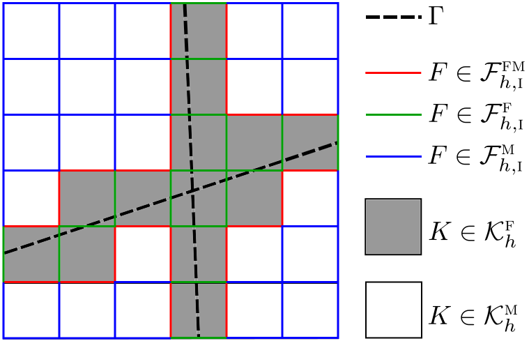
For the transport solver, we further divide into two subsets, and , where contains all fractured cells, , and , see Fig. 2a. The set of interior faces, are then partitioned into three subsets, , and , where are the set of faces between two fractured elements, is the set of faces between two matrix elements, and are the sets of faces between a fracture and a matrix element.
Remark 3.1.
In the situation where coincides with an element face , we need to choose which of the neighboring elements that belong to . One possibility is to choose the element for which is exterior, i.e., . For the numerical examples presented in Section LABEL:sec:results we have avoided this situation.
Jump and average operators
We define the jump operator over a face in the same way as we did for the jump over , see Eq. (2.1) and (2.4), where now defines the orientation. Furthermore, we denote by the weighted average operator on , defined as
| (3.1) |
where and . For we simply write without any subscript. For we define the jump and average operators as the one sided value, i.e.,
| (3.2) |
Finite dimensional function spaces
In our implementation we work with quadrilateral elements, but the all numerical methods can equally well be formulated on other elements, e.g., triangular. Denote by the reference element with coordinates , and by the mapping from to . With this, we denote by the tensor product of polynomial spaces of degree less than or equal to in each spatial direction, i.e.,
| (3.3) |
Next, denotes the reference element functions mapped to the actual element ,
| (3.4) |
We may now define the following function spaces of piecewise polynomials of order ,
| (3.5) | ||||
| (3.6) |
Moreover, we define the following spaces of piecewise constant functions (),
| (3.7) | |||
Finally, we denote by and the broken scalar products, i.e.,
3.2 Pressure problem
We follow [burman2017asf] and approximate the pressure solution with piecewise bilinear functions by restricting the weak formulation (2.11) to the finite dimensional subspace . Find such that
| (3.8) |
The following a priori error estimate for the pressure approximation was proved in [burman2017asf]. Let be the set of all elements which are node neighbors of , and let denote the mesh parameter in the vicinity of such that for all . Then it holds that
| (3.9) |
As a consequence, one should refine locally around the fractures until to obtain the optimal order of convergence in terms of .
Remark 3.2.
The estimate (3.9) was proved in [burman2017asf] for the simple geometry where is a smooth embedded interface in the interior of without boundary. It can be extended to the case where is represented as a graph. However, depending on the geometry of , we may loose some regularity of the solution (this is especially the case for terminating nodes in the interior of , e.g., in Fig. 1a), so that we must replace the term by for some . Yet, the condition is still sufficient to obtain the optimal convergence in terms of since refinement around also means refinement around the interface nodes.
3.3 Transport problem
We approximate the concentration solution by piecewise constants , and let on represent the concentration in the fractures, and on represent the concentration in the matrix. We use an upwind approximation of the concentration on element faces. The numerical scheme can be formulated as a zeroth order finite volume method (FV), or equivalently as a zeroth order Discontinuous Galerkin method (DG). We only express the FV formulation here, and refer to Appendix LABEL:app_DG for the DG formulation.
FV formulation
We integrate the matrix equation (2.14a) over to obtain the integral formulation
| (3.10) |
Similarly, for , we integrate the fracture equation (2.14a) over to obtain
| (3.11) |
The lowest order finite volume method is then obtained by replacing by . We use an upwind approximation on , i.e.,
| (3.12a) | |||
| where is a neighbor element of . If is a boundary face, we have | |||
| (3.12b) | |||
An equivalent upwind approximation of is used on .
Recall the definition of the vector valued jump in Eq. (2.4). The coupling term in Eq. (3.11), with replaced by , can be written as
| (3.13) |
Given a velocity approximation that is continuous in the interior of an element, we see that vanish as long as is not aligned with the element faces. This would result in no coupling between the fracture and the matrix. To overcome this, we approximate the flow between matrix and fracture by evaluating on the part of the element boundary that borders to matrix elements, i.e.,
| (3.14) |
where the upwind scheme (3.12) applies. Since on represents the approximation in the fracture, (3.14) is compatible with the condition (2.16). Given the low order method, the approximation (3.14) seems reasonable when combined with local refinement around .
We apply the implicit Euler (IE) method as time integrator. For simplicity, we use constant time steps , and let denote the approximation at , with , where is a projection operator from to .
To sum up, the FV-IE scheme can be formulated as follows. Find such that
| (3.15a) | |||||
| (3.15b) | |||||
Interpretation of solution
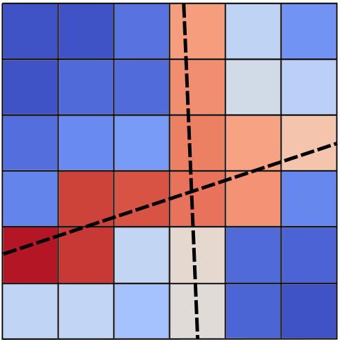
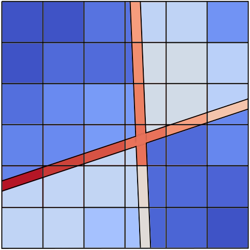
In the numerical method, , for , is represented by the value . However, also contains subdomains belonging to the matrix, whose concentration solution we represent by the solution in the neighboring matrix elements, see Fig. 2 for an illustrative example. For a single fracture the matrix concentration in to the left/right of is given by the solution in the left/right-neighboring matrix elements. For cells with intersecting or bifurcating fractures, this interpretation is slightly more complex, as divides into more than two subdomains. We refer to Appendix LABEL:app_interpretation for a well-defined interpretation.
3.4 Velocity model
We observe from the transport model, Eq. (3.15), that we need the flux (normal velocity) over the element faces. We denote the flux by and define it as
| (3.16) |
where is the unit tangent to oriented in the same direction as . Recall that so that gives the flow rate rather than the velocity. The reason for multiplying by for faces is that we want to work directly on so that when is integrated over we get the total flow rate through . With this definition of we can simplify two terms in Eq. (3.15b),
| (3.17) |
The term is either plus or minus depending on the orientation of .
For the coupled flow and transport problem, the velocity is derived from the pressure approximation . The pressure gradient, , is not continuous across element faces, so a naive flux approximation is to use the average value,
| (3.18) |
Recall the definition of the average operator in Eq. (3.1). As weights we follow [odsaeter2016pon] and use weights equal to the normal component of the permeability of the neighboring cell. Hence,
| (3.19) |
where are the permeabilities of the two cells sharing . For a fractured cell we use , and for , . In the case of isotropic permeability, i.e., , observe that such that
| (3.20) |
where is the effective face permeability (harmonic average).
We say that a flux approximation on is locally conservative if
| (3.21) |
As reported in [odsaeter2016pon], Eq. (3.18) does not define a locally conservative flux approximation. If coupled to the transport scheme one may get unphysical solutions due to artificial sinks and sources. To deal with this, we apply the postprocessing method presented in [odsaeter2016pon]. This method was shown to preserve accuracy of the velocity solution and was demonstrated to be especially beneficial for highly heterogeneous media.
Variationally consistent postprocessing of fluxes
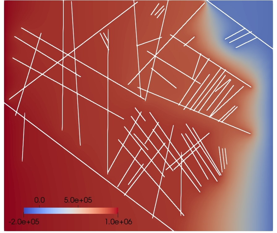
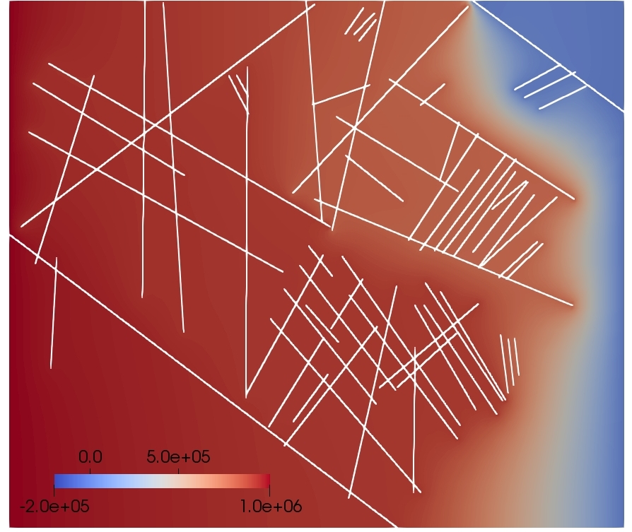
The core idea of the postprocessing method is to add a piecewise constant correction to under the constraint that the correction is minimized in a weighted norm, Figure 12: Benchmark 4 (pressure problem). Pressure approximations.


4.3 Coupled problems
We now couple the benchmark cases with the transport problem and solve for concentration. The coupled problem was not considered in [flemisch2018bfs].
4.3.1 Benchmark 1: Regular fracture network
For the transport problem we set , apply a boundary concentration on the inflow boundary (), and let . We consider the same computational meshes as for the pressure problem. In addition, we construct a reference mesh with 182674 elements where the fractures are fully resolved, i.e., at the fractures and away from the fractures. A reference solution is then obtained by a standard FV method on a continuous fracture model (no lower dimensional embedding), i.e., Eq. (LABEL:eq:FV-IE_pp_matrix) with and in the elements in the fracture domain. Time steps for the reference solution is .
Fig. 4.3.1 shows the velocity approximations in each of the six fractures for the different meshes. We see a very good agreement, in particular for the LR meshes. This is as expected since the velocity is derived from the pressure solution, which was shown earlier to have higher accuracy when refining around the fractures.
For the transport problem, we define a quantity of interest, QOI, as the flux of concentration out of the two fractures on the right boundary face,
| (4.37a) | ||||
| (4.37b) | ||||
For the reference solution, these quantities are calculated as
| (4.38a) | ||||
| (4.38b) | ||||
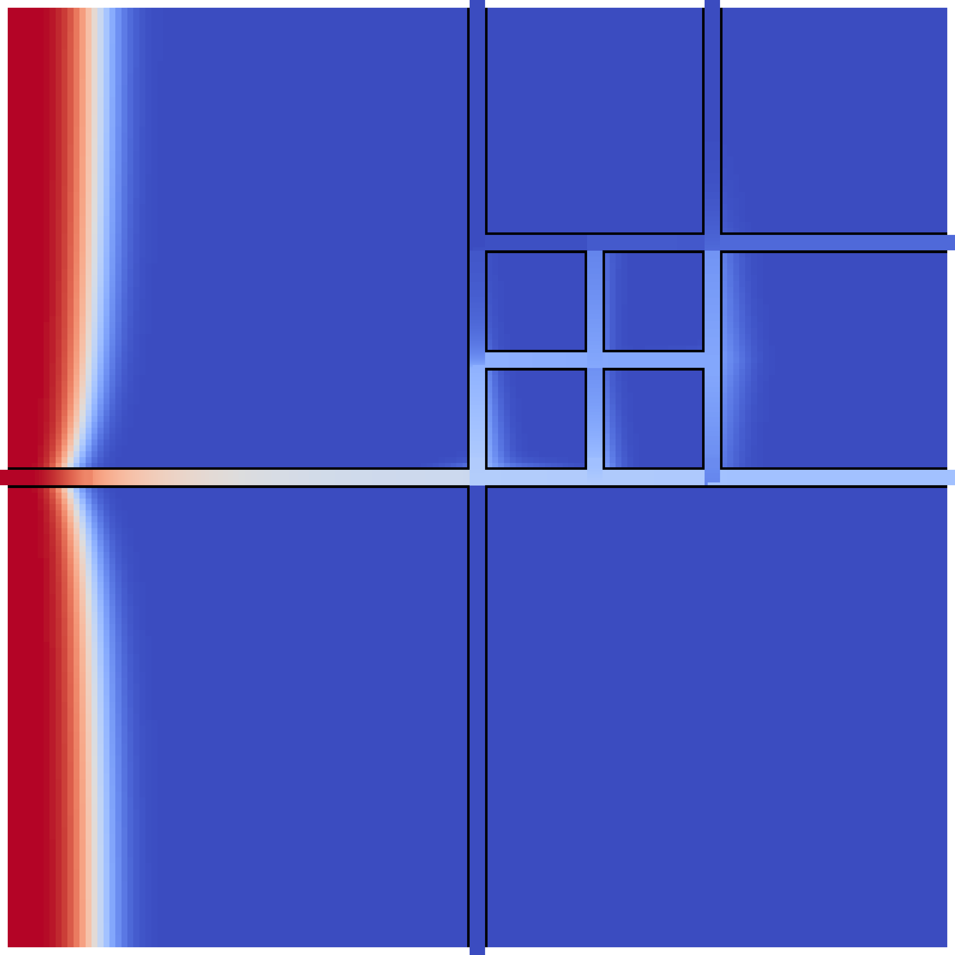
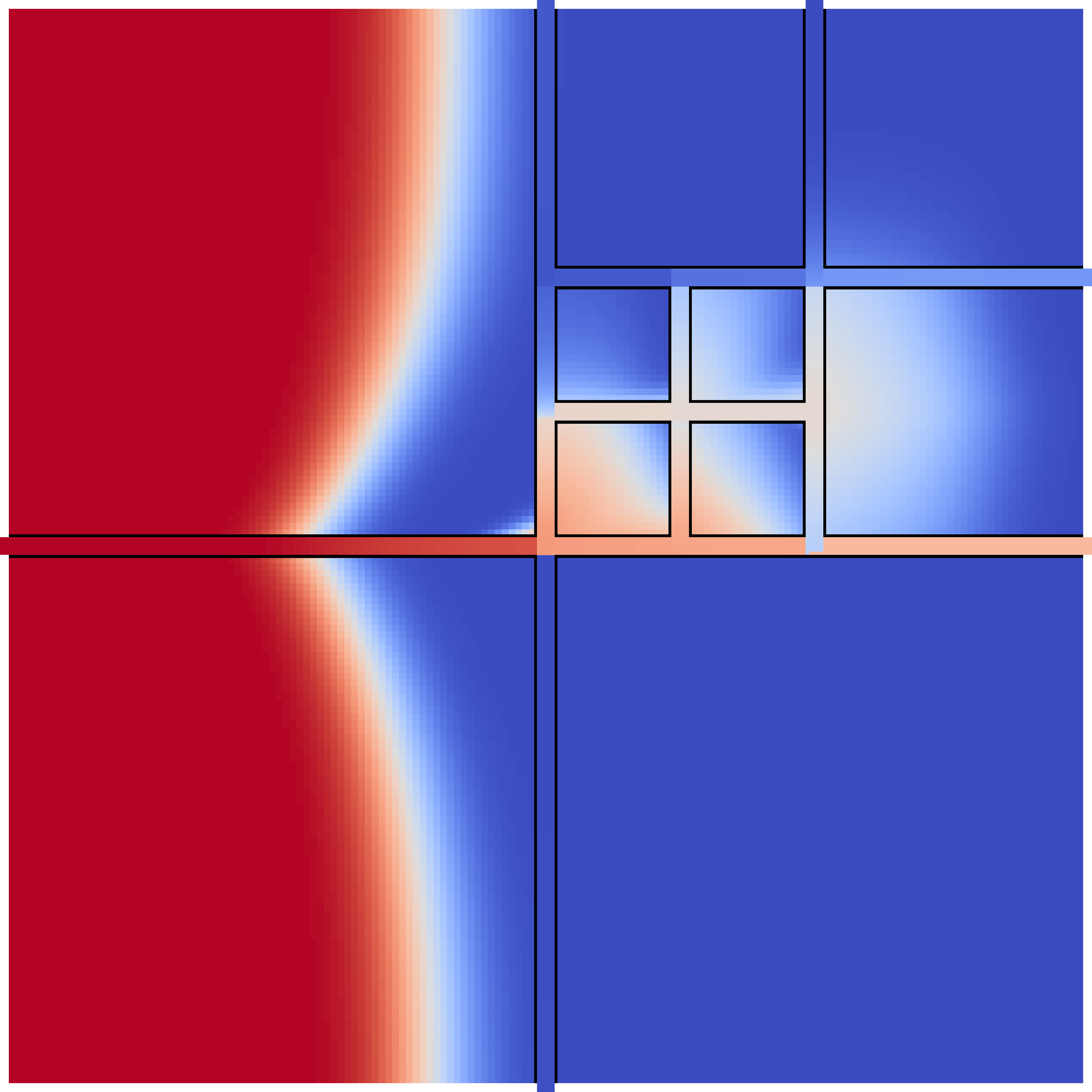
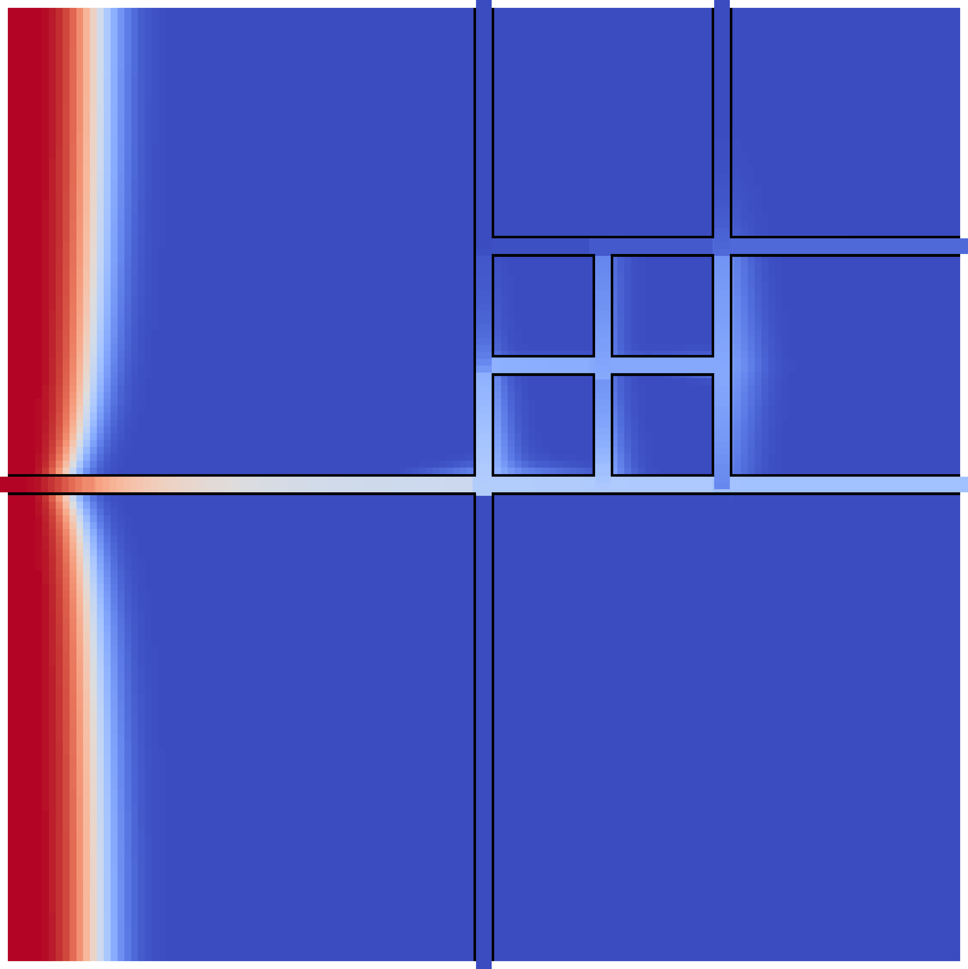
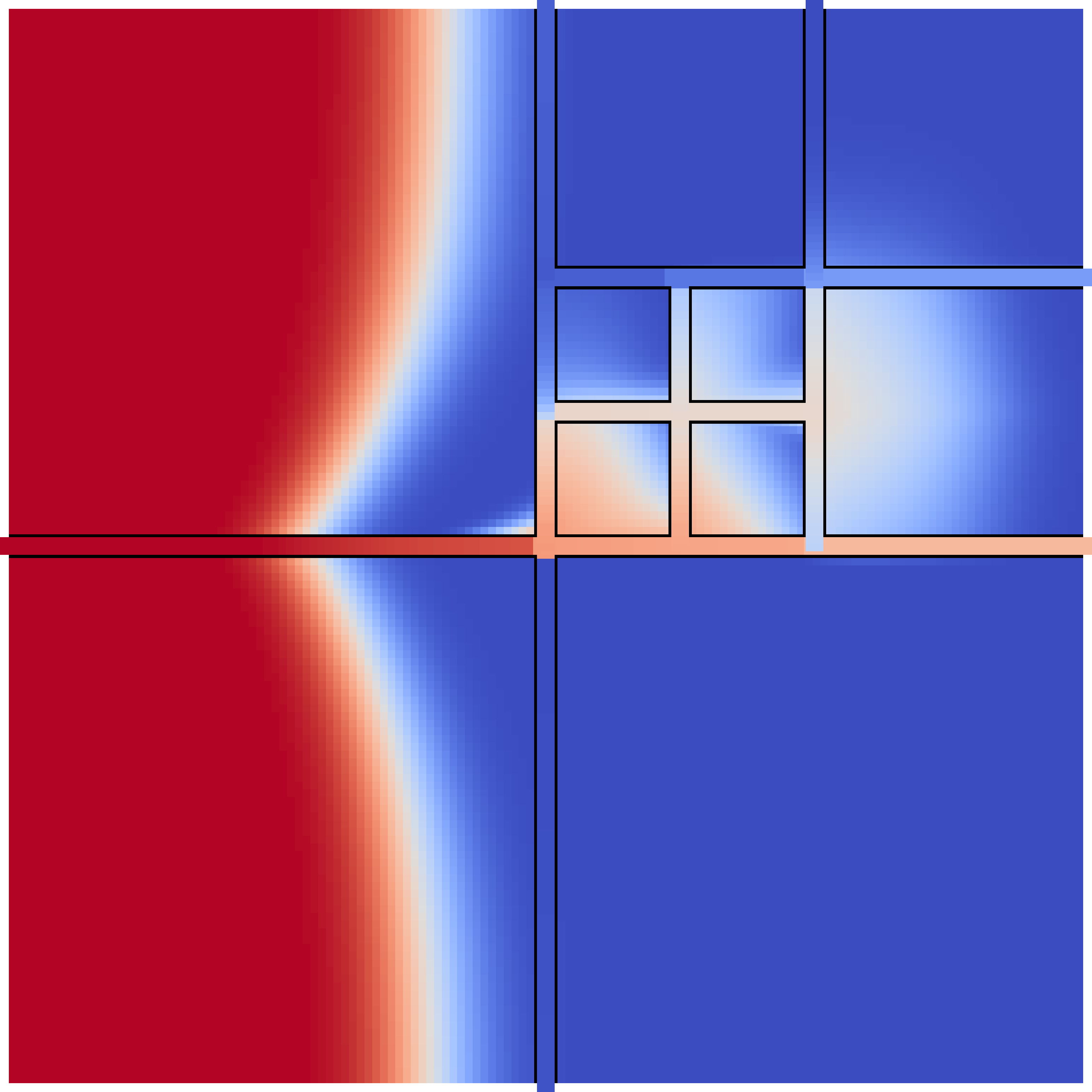
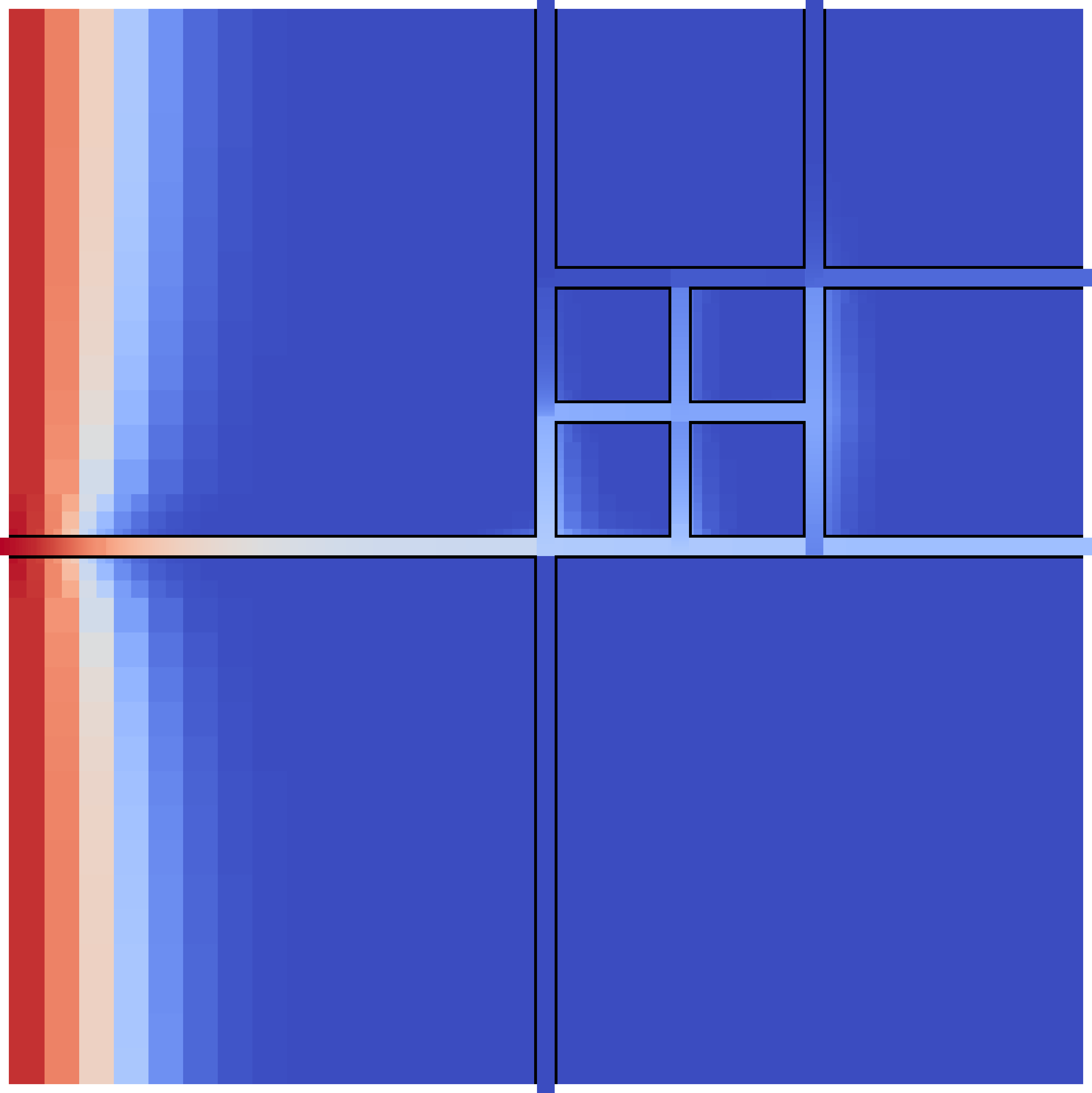
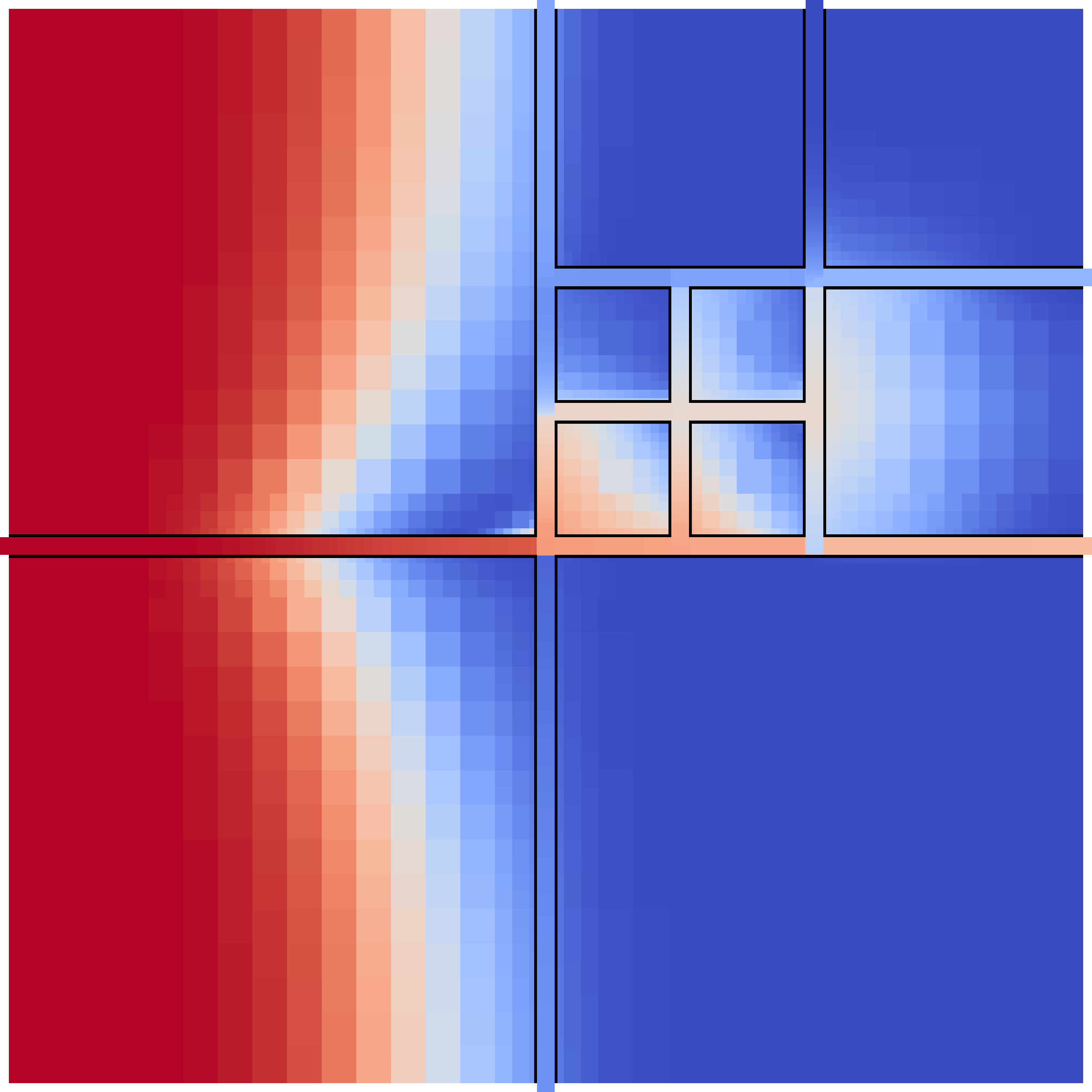
First, we solve the coupled problem on the four uniform meshes with , , , and , respectively, and on the three LR meshes with , , and , respectively. The concentration solution on the finest meshes are displayed in Figs. 4.3.1 and 17, while QOI is plotted against time for all meshes in Fig. 18.
We observe similar solutions for all meshes. At early times and in fracture 1 (), we have the best results on the LR meshes. However, the LR meshes are relatively coarse in the matrix. This causes large numerical diffusion and with time the concentration front in the matrix reaches the first vertical fracture (). This explains why the solution on the LR meshes becomes inaccurate at large times. A better meshing for the coupled problem would be to refine both close to the fractures and in the left half of .
At last, we ran a series of simulations on the UMR meshes with and compared to the reference solution by a norm over the fractures, see Fig. 19. We get a higher convergence than what is expected from the lowest order FV method.




4.3.2 Benchmark 4: A realistic case
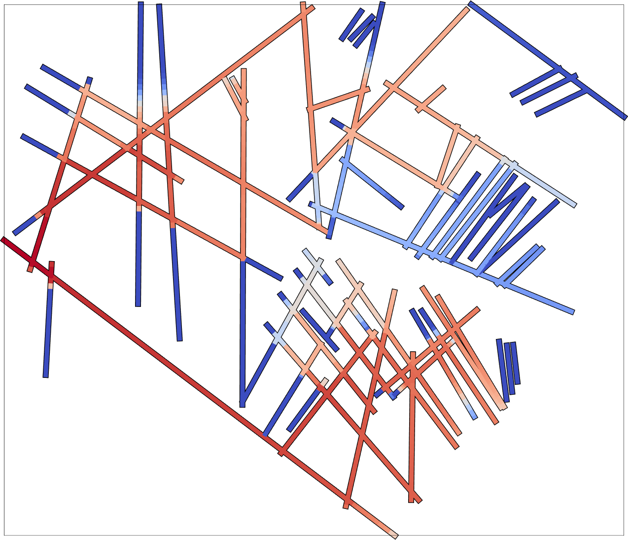
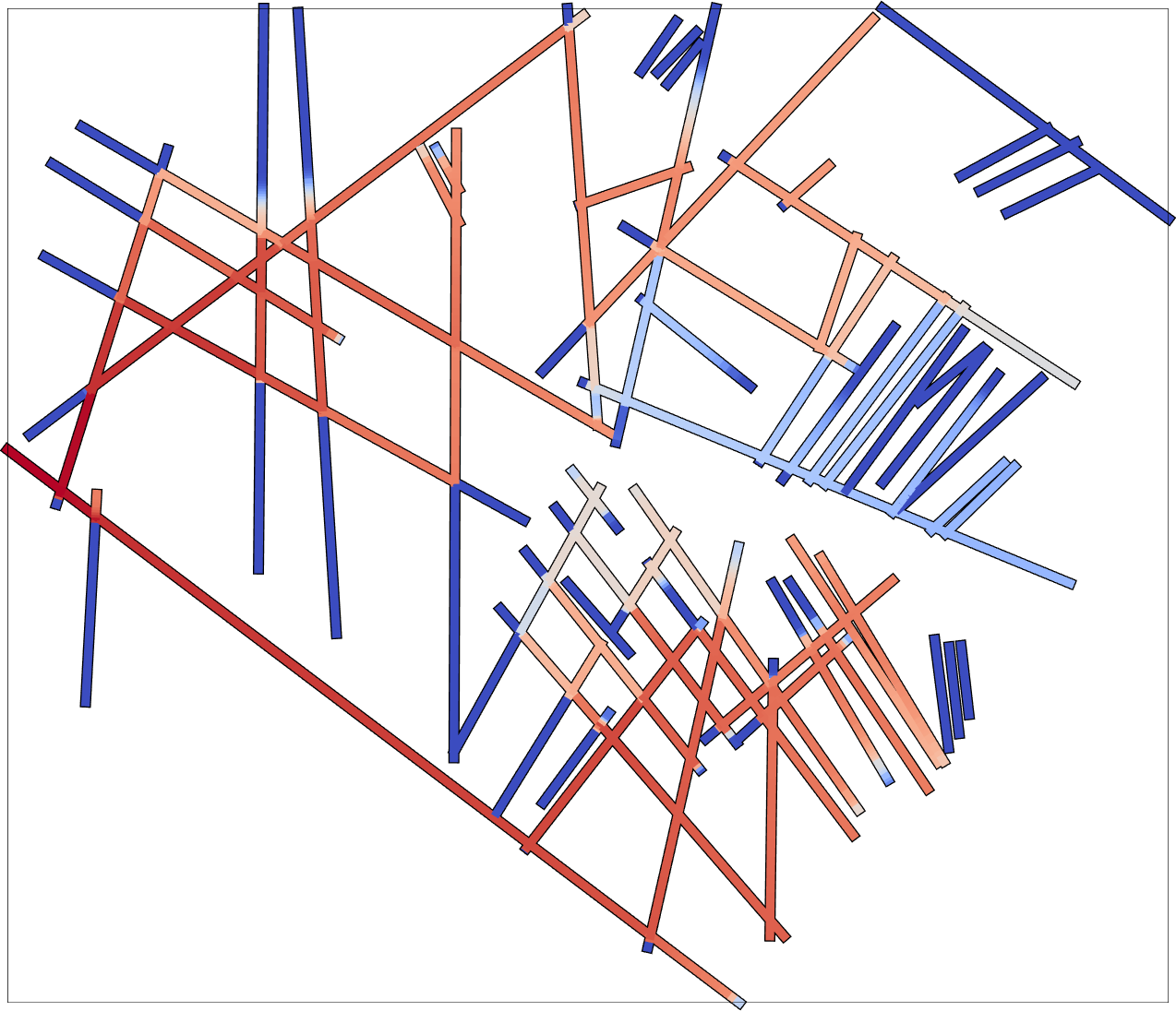
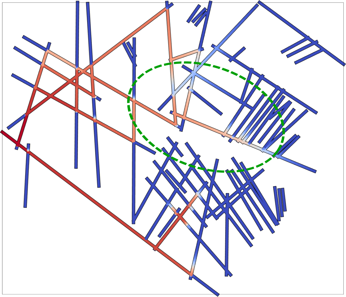
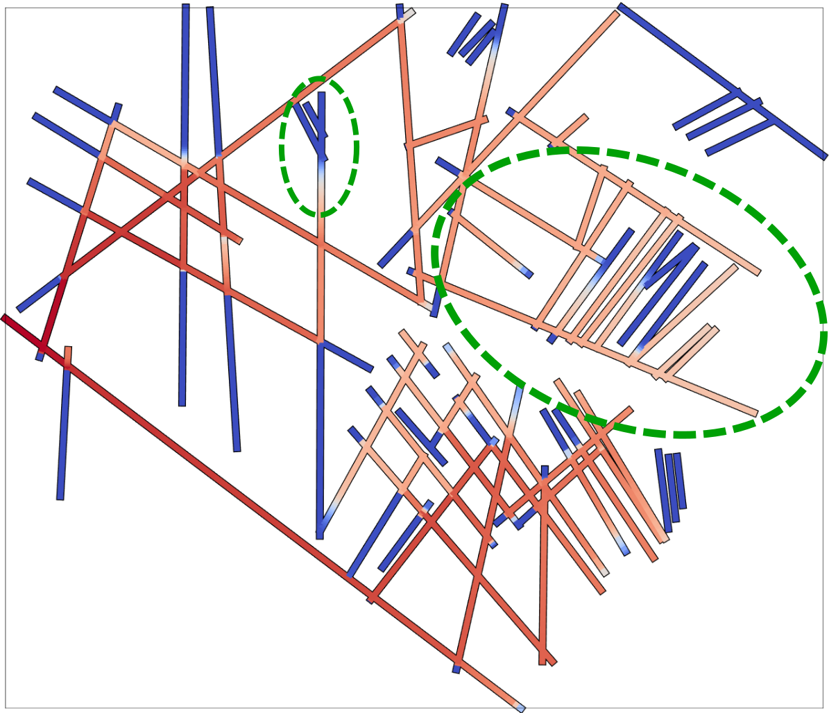
We now couple benchmark 4 to the transport problem, where and an inflow concentration is set on the left boundary face. Such problem was also considered in [fumagalli2017dve], but with different permeabilities. We set the end time for the simulations to years222..
First, we set hour (36500 time steps), and consider the meshes . Concentration solutions in the fractures are displayed in Fig. LABEL:fig:benchmark4_conc. Furthermore, convergence of the concentration in the fractures is demonstrated in Fig. LABEL:fig:benchmark4_conc_conv_space. Due to the high fracture permeability, nearly all transport take place in the fractures, and hence we do not display the matrix solution. We observe that we get reasonable good results even for the coarsest mesh. Furthermore, the results for clearly illustrates the importance of resolving the geometry, as the solution is far off in some of the fractures, even compared to which has much less DoFs. Convergence is rather slow due to the low order method.
Next, we ran a series of simulations on with days and compared to the solution with on the same mesh. The error over at is plotted against in Fig. LABEL:fig:benchmark4_conc_conv, and we observe linear convergence in time as expected.

