Revealing the formation and electrochemical properties of bis(trifluoromethanesulfonyl) imide intercalated graphite with first-principles calculations
Abstract
Graphite has been reported to have anion as well as cation intercalation capacities as both cathode and anode host materials for the dual ion battery. In this work, we study the intercalation of bis(trifluoromethanesulfonyl) imide (TFSI) anion from ionic liquid electrolyte into graphite with first-principles calculations. We build models for TFSI-Cn compounds with systematically increasing unit cell sizes of graphene sheet and investigate their stabilities by calculating the formation energy, resulting in the linear decrease and arriving at the limit of stability. With identified unit cell sizes for stable compound formation, we reveal that the interlayer distance and relative volume expansion ratio of TFSI-Cn increase as increasing the concentration of TFSI intercalate during the charge process. The electrode voltage is determined to be ranged from 3.8 V to 3.0 V at the specific capacity ranging from 30 mAh g-1 to 54 mAh g-1 in agreement with experiment. Moreover, a very low activation barrier of under 50 meV for TFSI migration and good electronic conductivity give a proof of using these compounds as a promising cathode. Through the analysis of charge transfer, we clarify the mechanism of TFSI-Cn formation, and reveal new prospects for developing graphite based cathode.
keywords:
Graphite intercalation compound , Dual ion battery , First-principles method , Ionic liquid anion , Cathode1 Introduction
Since the issue of global warming and climate change, originated from human activities of massively mining and consuming fossil fuels, is one of the greatest challenges of our time [1], clean energy technologies are becoming increasingly important. More and more peoples are interested in the clean energy sources, such as wind and solar power, and electric vehicles or hybrid electric vehicles. In such intermittent energy systems and electrified drive transporters, electrochemical energy storage devices like rechargeable batteries are indispensable components. Lithium ion batteries (LIBs) have been dominating battery markets for portable electronic devices since their commercialization in 1991, due to their high specific capacity (low weight) and high energy density (low volume). However, the growing demand of LIBs and their introduction into vehicles have raised concerns about the low abundance and thus high cost of lithium resources [2, 3], together with other technical problems of safety, minimum charging time and cycle life [4]. In recent years, therefore, numerous research studies have been made on alternatives with the same operational mechanism to LIBs based on high abundant and low cost elements such as sodium [5, 6, 7] and potassium [8, 9] towards a large-scale energy storage device with a reasonable cost.
Electrodes (cathode and anode) are the key components that determine the performance of alkali ion batteries, where alkali cations (, , ) intercalate/de-intercalate into/from the electrodes during the charge/discharge process. The standard anode widely used in commercial alkali ion batteries might be graphite because of its well-layered structure, composed of two-dimensional (2D) graphene layers bound through the weak van der Waals (vdW) attraction, which allows easy formation of graphite intercalation compounds (GICs) [10]. As electron donors, alkali metals (AMs) can form donor-acceptor type AM-GICs with the ionic bonding between AM and graphene layer, of which strength decreases as decreasing the atomic number (increasing the electropositivity) from Cs to Na, with the exception of Li due to the strong covalent bonding of LiC [11, 12, 13]. From the theoretically calculated formation energies, it was found that for the stage 1 GICs the stability is in the order of , while is thermodynamically unstable [11]. Moreover, the redox potential for K/ ( V) vs. standard hydrogen electrode is lower than for Na/ ( V) and close to Li/ ( V), suggesting higher cell voltage for K-ion battery (KIB) compared to Na-ion battery (NIB) and similar value to LIB. On the other hand, the larger radius ion was found to diffuse more smoothly in graphite due to the activation barriers in the order of Li Na K [12, 14]. Together with a relatively high abundance, a low cost and environmental friendliness of potassium, these indicate more potentiality of KIB rather than NIB and LIB.
For KIB to become competitive with LIB in battery markets, however, suitable cathode material with a high capacity and a high cell voltage should be developed. As for LIBs and NIBs, many kinds of materials, such as layered metal oxides [15, 16] and polyanionic compounds [17, 18], have shown promising properties. Alternatively, based on the unique amphoteric character of graphite that can accommodate both cations (electron donor) and anions (acceptor), graphite was suggested to be used as the cathode host as well, namely dual-ion battery (DIB) or dual-graphite battery (DGB), where AM cations and complex anions simultaneously intercalate/de-intercalate into the graphite based anode and cathode during the charge/discharge process [19, 20, 21, 22, 23, 24, 25, 26]. Here, the anions are from ionic liquids used as electrolyte in ion batteries, which are typically hexafluorophosphate () [22], perchlorate () [27], fluorosulfonyl imide (FSI, ), and bis(trifluoromethanesulfonyl) imide (TFSI, ) [28, 29, 30, 31, 32, 33, 34, 35, 36]. Recently, Beltrop et al. [37] reported a novel potassium-based DGB (K-DGB), composed of -butyl--methyl-pyrrolidinium TFSI () + 0.3 M potassium TFSI () + 2 wt% ethylene sulfite (ES) as electrolyte and graphite as both the anode and cathode hosts, showing a relatively high reversible capacity of 230 mAh g-1 and a high potential range from 3.4 V to 5.0 V vs. K/. This requires to reveal the mechanism of formation and electrochemical properties of TFSI-GICs by applying the theoretical and computational method. To the best of our knowledge, however, there is no theoretical study on TFSI-GICs, although some simulation works for TFSI molecule [28, 29, 33, 34] and first-principles work for other anion GICs such as - and -GICs [38] have been reported.
In this study, we apply the first-principles method within the density functional theory (DFT) framework to TFSI-GICs, together with graphite and TFSI molecule, aiming to reveal energetics, structures, electrochemical properties, and formation mechanism. Supercells of TFSI-Cn, where the carbon atom number is determined from unit cells of graphene sheet with various sizes, are built, and their formation and interlayer binding energies are calculated. The electrode voltage, activation barrier for TFSI migration, and electronic conductance are considered. To obtain insights for GIC formation, we perform an analysis of electronic density difference and atomic charge.
2 Computational methods
The DFT calculations were performed with the pseudopotential plane wave method as implemented in Quantum ESPRESSO code (version 5.3.0) [39], using the ultrasoft pseudopotentials provided in the package. 111We used the Vanderbilt-type ultrasoft pseudopotentials C.pbe-van_ak.UPF, N.pbe-van_ak.UPF, S.pbe-van_bm.UPF, O.pbe-van_ak.UPF, and F.pbe-n-van.UPF, which are provided in the package. Here, valence electrons of C 2s22p2, N 2s22p3, O 2s22p4, S 3s23p4, and F 2s22p5 were explicitly considered. For exchange-correlation (XC) interaction between the valence electrons, Perdew-Burke-Ernzerhof (PBE)[40] functional within the generalized gradient approximation (GGA) was used, and using the vdW-DF2 functional [41], the dispersive energy was added. The cutoff energies were set to be 40 Ry for a plane wave basis set and 400 Ry for an electronic density. An isolated TFSI molecule was simulated using the cubic supercell with a lattice constant of 17 Å, which is large enough to prevent the artificial interaction between the neighbouring images. Only point in the Brillouin zone (BZ) was used for this isolated molecule. To make modelling stage 1 GICs, TFSI-Cn, one TFSI molecule is placed between the graphene sheets in -stacked graphite with various cell sizes of , , , , , and , which give the carbon atom number as = 18, 24, 32, 40, 50, 60 and 72, respectively. The special -points for the BZ sampling were constructed using the and Monkhorst-Pack meshes for the and cells for atomic relaxations, while denser -points using the and meshes for DOS calculations. These computational parameters of cutoff energy and -point mesh could produce the absolute total energy convergence better than 1 meV per atom. In the atomic relaxations, the forces on each atom converged to within Ry Bohr-1.
In order to study of the TFSI intercalation into graphite, we assumed the following process [38],
| (1) | |||
| (2) |
The formation energy of TFSI-Cn compound per formula unit (four carbon atoms) can be calculated as follows,
| (3) |
where , , and are the DFT total energies of TFSI-Cn supercell, graphite unit cell, and isolated TFSI supercell, respectively. The negative formation energy indicates that the GIC is thermodynamically stable, i.e. exothermic formation of the GIC from graphite and TFSI molecule. The interlayer binding energy (or exfoliation energy) per carbon atom can be calculate as follows [42],
| (4) |
where is the interlayer distance, the equilibrium interlayer distance, and might be 20 Å over which the total energy is little changed. To calculate the activation barrier for TFSI migration inside graphite, the climbing image nudged elastic band (CI-NEB) method [43] was applied to TFSI- compound using seven image points and convergence threshold of 0.05 eV Å-1 for the force on band orthogonal to path. The supercell dimensions were fixed at the optimized one, while all atoms were relaxed.
3 Results and discussion
3.1 Structure and energetics
In compliance with the well-known fact that standard XC functionals within GGA or LDA poorly describe graphite and other carbon layered materials, and therefore, vdW functional should be adopted [14, 42, 44, 45], we first assessed the reliability of various vdW functionals by calculating lattice constants of graphite. Table S1 shows that all PBE + vdW functionals adopted in this work, even PBE itself, reproduced the experimental in-plane lattice constant (2.461 Å [46]), governed by the covalent ( and ) bonding, while vdW-DF2 functional [41] (relative error 1.64%) yielded the best agreement with the experimental interlayer distance (3.353 Å [46]). As the interlayer distance is perpendicular to the graphene sheet and along the direction of the vdW interaction, vdW-DF2 functional was decided to be the most reliable one for graphite and further GICs. For a check of the stability of graphite, the interlayer binding energy was calculated to be 78 meV per atom. When compared with the experimental values in the range of 35 52 meV [47, 48], our calculation gave a slight overestimation, but close to other theoretical results, such as 69 meV with the inclusion of vdW energy by Tasaki [38], and 61 74 meV with the combination of DFT and perturbation theory by Dapper et al. [49].
| TFSI-Cn | ||||||
| TFSI | 18 | 24 | 32 | 40 | 50 | |
| Bond length (Å) | ||||||
| SN | 1.642 | 1.644 | 1.623 | 1.618 | 1.616 | 1.614 |
| SO | 1.463 | 1.453 | 1.451 | 1.449 | 1.448 | 1.447 |
| SC | 2.027 | 1.901 | 1.905 | 1.901 | 1.901 | 1.900 |
| CF | 1.343 | 1.370 | 1.377 | 1.379 | 1.381 | 1.383 |
| Bond angle (degree) | ||||||
| SNS | 130.06 | 126.07 | 126.19 | 125.64 | 125.68 | 125.26 |
| NSO | 112.28 | 116.52 | 115.57 | 115.73 | 115.88 | 115.98 |
| 105.61 | 106.55 | 107.67 | 108.09 | 108.21 | 108.51 | |
| NSC | 107.81 | 100.60 | 103.46 | 103.33 | 103.31 | 103.20 |
| OSC | 105.44 | 105.73 | 104.23 | 104.02 | 103.86 | 103.69 |
| OSO | 119.59 | 119.58 | 119.65 | 119.53 | 119.51 | 119.46 |
| SCF | 105.97 | 109.38 | 110.45 | 110.90 | 111.12 | 111.33 |
| FCF | 112.74 | 109.56 | 108.47 | 108.00 | 107.77 | 107.54 |
| Dihedral angle (degree) | ||||||
| SNSC | 55.74 | 84.94 | 88.28 | 87.77 | 87.87 | 87.70 |
| Molecular volume (Å3) | ||||||
| 164.4 | 161.6 | 163.7 | 162.6 | 163.7 | 163.3 | |
We then considered the isolated TFSI molecule, as assumed in this work according to Eq. 2, although TFSI exists in the anion state in the form of room-temperature ionic liquids, such as [29, 30, 35], [37] and [30, 33, 34, 35, 36, 37], used as electrolyte for polymer batteries and alkali ion batteries. The molecular structure was optimized after conformation search and analysed with a comparion to those of TFSI-Cn compounds. In addition, the electrostatic potential and frontier molecular orbitals such as the highest occupied molecular orbitals (HOMO) and the lowest unoccupied molecular orbitals (LUMO) were calculated. Since TFSI has the molecular structure of and the terminal group can rotate along the bond to give rotational isomers, there are typically two conformations according to the dihedral angles; () and () [28, 29]. In accordance with the previous theoretical works employing the Gaussian orbital method [28, 29] and force-field molecular dynamics [33, 34], it turned out from conformation search with the systematic grid scan method that the conformer is the energetically lowest conformer.
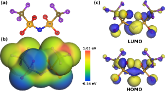
This conformer was placed within the cubic supercell with a lattice constant of 17 Å to perform atomic relaxation using the vdW-DF2 functional. Effective screening medium method [50] was applied to this isolated molecule as implemented in the code. The optimized molecular structure of TFSI molecule is depicted in Figure 1(a), and the chemical bonding properties such as bond length, bond angle and dihedral angle are presented in Table 1. When compared with those by Gaussian method [28, 29], the bond lengths were calculated to be slightly larger in overall, especially bond length, possibly due to the inclusion of vdW interaction. To obtain qualitative insight for the electrochemical reduction stability, we present electrostatic potential maps in Figure 1(b). The regions of lowest electrostatic potential (Figure 1(b), bluest region) are found in the vicinity of O atoms, whilst the regions of highest electrostatic potential (Figure 1(b), reddest region) around the F, C and S atoms, indicating the electrochemical reduction will be occurred by oxygen atoms. We also plotted the frontier molecular orbitals including HOMO and LUMO, as presented in Figure 1(c). It is interesting that around S atoms neither HOMO nor LUMO is found, indicating a different role of S atom from other atoms. In addition, the intra-molecular charge separation upon excitation can not be said to occur due to no clear separation between HOMO and LUMO distribution regions.
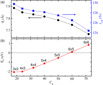
With the structural and energetic characteristics of graphite and TFSI molecule, next, we applied the same DFT scheme to the TFSI-Cn compounds under study. Due to a certain amount of TFSI molecular volume, the minimum cell size of 2D graphene sheet should be determined to intercalate it into graphite. The molecular volume of TFSI was calculated to be 152.9 or 164.4 Å3 based on the vdW or Connolly surface, which gives a radius of 5.35 or 5.48 Å when reduced to the sphere. Then, the graphene sheet with a cell width of 7.41 Å should be minimal for TFSI to be fully placed inside the sheet. On the other hand, it was found that the stability of ternary GICs with the co-intercalate consisted of AM atom and diglyme solvent molecule, as estimated by the formation energy, reduces as decreasing the concentration of intercalate, and even the GIC becomes unstable under a certain value of concentration [42]. Thus, we calculated the formation energies of TFSI-Cn as systematically increasing the number of carbon atom in graphene sheet, i.e., increasing the cell size of graphene sheet from ( = 18) to ( = 72) (decreasing the TFSI concentration). Figure 2 shows the formation energy as a function of carbon atom number, together with the interlayer distances and volume expansion ratios relative to pristine graphite. It is seen that the formation energy has the minimum value as 2.07 eV in the compound, and increases linearly as increasing the carbon atom number from = 24 (similar value of 2.01 eV to ), becoming positive over cell ( = 60). This indicates that TFSI-Cn formation over = 60, from graphite and TFSI molecule, is not suitable thermodynamically, and therefore, TFSI-Cn with = 18, 24, 32, 40, and 50 were considered for further calculation and analysis.
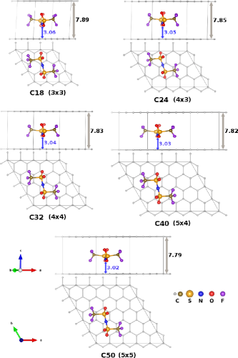
Figure 3 shows the atomistic structures of these GICs, optimized with PBE + vdW-DF2 functional. It was shown that the interlayer distance has the maximum value in TFSI- as 7.89 Å, determined through the variable cell optimization, and decreases as a linear function of carbon atom number, while the relative volume expansion ratio also decreases from 130% () to 127% () (see Figure 2(a)). The height of N atom to the bottom graphene sheet decreases monotonically as increasing the carbon atom number. When compared with the experimental values of Å and % [23, 37], our calculation gave underestimation in accordance with the above-mentioned slight overestimation of interlayer binding. In Table 1, we present the bond length, bond angle, dihedral angle and molecular volume of TFSI molecule intercalated into graphite, in comparison with those in isolated state. It was observed that the bond lengths of , and lessens upon the intercalation of TFSI into graphite, whilst the bond lengthens. The bond angles changes also systematically in overall, and in particular, the dihedral angle of changed greatly from 56 degree in isolated state to over 84 degree in TFSI-Cn GICs. These correlate well with the molecular volume contraction from 164.4 Å3 in isolated state to 161.6 163.7 Å3 in GICs. Note that the contraction of TFSI molecular volume upon intercalation is the most remarkable in the cell (), the highest concentration of intercalate.

As the another energetic property of GICs in addition to formation energy, we calculated the interlayer binding energy (Eq. 4), representing the strength of binding between graphene sheets, as shown in Figure 4. The interlayer binding energy of TFSI-Cn compounds decreases in magnitude as increasing the cell size of graphene sheet, indicating a decrease of binding strength, which correlates well with the tendency of formation energy. Moreover, those with = 18 (148 meV), 24 (122 meV), 32 (93 meV) are bigger than that of graphite (78 meV), indicating that the GIC formation in these cases enhances the interlayer binding compared with graphite due to a change of bonding from vdW characteristics to ionic one. If the number of carbon atom is over 32, i.e. =40 (73 meV) and 50 (58 meV), however, those are smaller than that of graphite, indicating a weakening of interlayer binding.
3.2 Electrochemical characteristics
In this subsection, we consider typical electrochemical characteristics of TFSI-Cn compounds, such as electrode voltage, intercalate diffusion and electronic conductivity. As the electrode voltage is one of the most crucial electrochemical properties, better cathode material should possess higher electrode voltage. Providing that, during the charge process in DIB, TFSI-GIC transforms from the compound of higher carbon atom number (lower concentration of TFSI intercalate) to that of lower one (higher concentration of TFSI intercalate), we can change the notation of TFSI-GICs from TFSI-Cn to TFSI-C60, where using C60 GIC as the starting compound. Then, using the total energies of the compounds, the electrode voltage can be calculated as follows,
| (5) |
where is the elementary charge of electron. It should be noted that, although TFSI- compound was estimated to be unstable, it can be used as a reference compound due to its low positive formation energy as 0.10 eV (Figure 2(b)).
| SC | ||||||
|---|---|---|---|---|---|---|
| Cn | (Å) | (%) | (eV) | (meV) | (mAh g-1) | (V) |
| 18 | 7.89 | 129.76 | 2.07 | 148 | 54.0 | 3.00 |
| 24 | 7.85 | 128.44 | 2.01 | 122 | 47.2 | 3.42 |
| 32 | 7.83 | 128.39 | 1.61 | 93 | 40.3 | 3.56 |
| 40 | 7.82 | 128.11 | 1.15 | 73 | 35.2 | 3.64 |
| 50 | 7.79 | 127.47 | 0.55 | 58 | 30.4 | 3.81 |
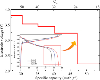
Figure 5 shows the electrode voltage step as progressing the charge process, i.e. increasing the number of carbon atom of graphene sheet and accordingly the specific capacity. It was found that as decreasing the carbon atom number, i.e. cell size of graphene sheet, the specific capacity increases from 30.4 mAh g-1 (TFSI-) to 54.0 mAh g-1 (TFSI-), yielding the voltage steps from 3.81 V to 2.23 V. When compared with the experimental voltage range from 5.0 V to 3.4 V vs. K/ and specially from 4.4 V to 3.4 V corresponding to the capacity range from 30 to 45 mAh g-1, our calculated values were in reasonable agreement with the experiment. Table 2 presents an overview of structural, energetic, and electrochemical characteristics of TFSI-Cn compounds with from 18 to 50, including interlayer distance, relative volume expansion ratio, formation energy, interlayer binding energy, specific capacity and average electrode voltage.

The mobility of intercalate inside space formed between graphene sheets can determine the rate capability and cycling stability of graphite based electrode. In this respect, we calculated the activation barriers for TFSI migrations along possible paths across one carbon hexagon by applying the CI-NEB method [43] to TFSI- GICs. The activation barrier was calculated to be very low like at most 35 meV, as shown in Figure 6 (see Figure S1-S3 for those along other paths). When compared with those for alkali cation (0.2 - 0.4 eV) [12] and co-intercalate composed of AM and solvent molecule (0.1 0.6 eV) [14, 42] migrations inside graphite, this is surprisingly so low that TFSI can migrate almost freely with a very long diffusion length. This suggests a very fast charging time and very long cycling life in DIB. However, it should be noted that much higher activation energy can be required for the first anion uptake, due to the initial widening of the interlayer distance between graphene sheet against the attracting vdW forces.

The electronic conductivity is also an important property for understanding the battery operation. As we assumed for anion intercalation into graphite, the anion releases an electron before stating the intercalation, and the electron can be transmitted through GICs to the current collector. Therefore, TFSI-Cn compound should be an electronic conductor like many other electrode materials. The electron conductivity of materials can be judged qualitatively by analysing the electronic density of states (DOS). Figure 7 presents the total DOS in isolated TFSI molecule, graphite, and TFSI-Cn compounds, with angular momentum projected DOS for the case of graphite and atom resolved partial DOS for the cases of GICs. As already being well-known, graphite was confirmed to have good in-plane electronic conductivity due to an existence of electron states over the Fermi level, but no inter-plane conductivity due to and or states away from the Fermi level. Upon TFSI intercalation into graphite, the in-plane conductivity of graphene sheet was observed to preserve well due to electronic states of graphene sheets around the Fermi level in TFSI-Cn compounds. When increasing the concentration of TFSI intercalate (decreasing the carbon atom number), the unoccupied states of graphene are getting further away from Fermi level, indicating a reduction of electronic conductivity. In addition, the overlap of electronic states between graphene sheet and TFSI molecule was observed below and above the Fermi level, indicating hybridization between bonding orbitals of graphene sheet and molecular orbitals of TFSI molecule.
3.3 Electronic charge transfer
Finally, we performed an analysis of electronic density difference and atomic charge to obtain insights into the charge transfer occurred upon TFSI intercalation into graphite forming TFSI-Cn compounds and the chemical bonding between TFSI and graphene layer. This can be meaningful for understanding the mechanism of TFSI-GIC formation. The electronic density difference () is obtained as the difference between the electronic densities of the TFSI-Cn compounds () and those of the graphene sheet () and TFSI molecule () as follows,
| (6) |
where the atomic positions are fixed as the optimized one.
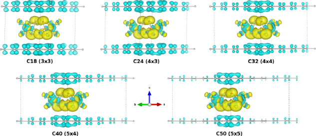
Figure 8 shows the electronic density differences with an isosurface plot at the value of 0.002 Å-3. On condition that the positive value (yellow colour) indicates the electronic density accumulation and the negative value (cyan colour) the density depletion, it was found that the valence electronic density of the graphene layer has transferred almost totally to the TFSI molecule, and the extent of charge transfer decreases gradually as increasing the cell size of graphene layer due to an intuitive gradual reduction in the amount of charge depletion on the graphene layer. Nevertheless, the amount of electronic density difference around the carbon atoms facing the oxygen and nitrogen atoms of TFSI is kept almost to be constant. Moreover, the distribution of electronic density difference around the TFSI molecule also seems to be little changed. Inside the TFSI molecule, the major portion of charge accumulation is found around the O and N atoms, confirming the ionic character of the bonding between the nitrogen as well as oxygen atoms of TFSI molecule and the facing carbon atoms of graphene layer.
To quantitatively estimate the amount of transferred charge, the atomic charges calculated by using the Löwdin method were analysed. As shown in Table S2, upon the intercalation of TFSI into graphite, graphene layer donates electrons due to a decrease of its average Löwdin charge per atom from 3.962 in graphite to 3.936 () 3.902 () in GICs, while TFSI molecule plays a role of electron acceptor due to an increase of its Löwdin charge from 5.973 in the isolated state to 6.036 in GICs. As increasing the cell size of graphene sheet in the cases of GICs, the amount of donated electron by graphene layer decreases due to an increase of Löwdin charge per carbon atom, but the average charge of TFSI molecule per atom keeps a constant, which are in good agreement with the intuitive observation of electronic density differences. Inside the TFSI molecule, only the charge of S atom decreases upon the intercalation, while those of other atoms increase, indicating that S atoms also donate electrons, as already mentioned in the analysis of molecular orbitals.
4 Conclusions
With first-principles calculations using the PBE + vdW-DF2 functional, we studied the intercalation of TFSI anion into graphite, aiming to identify the atomistic structures, energetics, electrochemical properties, and electronic charge transfer of TFSI-Cn compounds for dual ion battery application. We made modelling of these compounds using various sizes of graphene unit cells from to , producing the number of carbon atoms from 18 to 72, and checked their formation energies, clarifying the linear increase of formation energy as increasing the cell size and thermodynamic instability of GICs over = 60 due to positive formation energies. Together with the decrease of interlayer binding energy as well, this indicates that at low concentration of TFSI intercalate TFSI-Cn compounds can not be formed. As increasing the carbon atom number in TFSI-Cn compounds, the interlayer distance was found to decrease from 7.89 Å () to 7.79 Å (), and accordingly the volume expansion ratio relative to graphite also decreases from 130 % to 127% in slight underestimation compared with experiment. The average electrode potential during the charge process was determined to be ranged from 3.8 V to 3.0 V at the specific capacity range from 30 mAh g-1 to 54 mAh g-1 in reasonable agreement with experiment. In particular, the activation barrier for TFSI migration inside graphite was calculated to be quite low like under 50 meV, suggesting the very fast charging time. The analysis of DOS indicates that these compounds can be electron conductors and the conductivity seems to decrease as increasing the concentration of intercalate. Through the analysis of electronic density difference and atomic charges, the graphene layer and TFSI molecule in these compounds play role of electron donor and acceptor, respectively. The calculation results clarify the mechanism of TFSI-Cn formation and reveal new prospects for developing graphite based cathode materials of alkali ion batteries.
Acknowledgments
This work was supported partially from the State Committee of Science and Technology, Democratic People’s Republic of Korea, under the fundamental research project “Design of Innovative Functional Materials for Energy and Environmental Application” (No. 2016-20). The calculations in this work were carried out on the HP Blade System C7000 (HP BL460c) that is owned by Faculty of Materials Science, Kim Il Sung University.
Appendix A. Supplementary data
Supplementary data related to this article can be found at URL.
Notes
The authors declare no competing financial interest.
References
- Par [2015] EUROPEAN COMMISSION Climate Action. Annual Conference of Parties (COP) at COP21 at Stade de France (Gate E) in Paris, http://ec.europa.eu/clima/policies/international/negotiations/paris/index_en.htm, 2015.
- Tarascon [2010] J.-M. Tarascon, Is lithium the new gold?, Nature Chemistry 2 (2010) 510.
- Goodenough and Kim [2010] J. B. Goodenough, Y. Kim, Challenges for Rechargeable Li Batteries, Chem. Mater. 22 (2010) 587–603.
- Zhang et al. [2017] H. Zhang, C. Mao, J. Li, R. Chen, Advances in electrode materials for Li-based rechargeable batteries, RSC Adv. 7 (2017) 33789–33811.
- Hwang et al. [2017] J.-Y. Hwang, S.-T. Myung, Y.-K. Sun, Sodium-ion batteries: present and future, Chem. Soc. Rev. 46 (2017) 3529–3614.
- Yabuuchi et al. [2014] N. Yabuuchi, K. Kubota, M. Dahbi, S. Komaba, Research Development on Sodium-Ion Batteries, Chem. Rev. 114 (2014) 11636–11682.
- Sawicki and Shaw [2015] M. Sawicki, L. L. Shaw, Advances and challenges of sodium ion batteries as post lithium ion batteries, RSC Adv. 5 (2015) 53129–53154.
- Pramudita et al. [2017] J. C. Pramudita, D. Sehrawat, D. Goonetilleke, N. Sharma, An Initial Review of the Status of Electrode Materials for Potassium-Ion Batteries, Adv. Energy Mater. (2017) 1602911.
- Ji et al. [2017] B. Ji, F. Zhang, X. Song, Y. Tang, A Novel Potassium-Ion-Based Dual-Ion Battery, Adv. Mater. 29 (2017) 1700519–1700525.
- Dresselhaus and Dresselhaus [2002] M. S. Dresselhaus, G. Dresselhaus, Intercalation compounds of graphite, Adv. Phys. 51 (2002) 1–186.
- Moriwake et al. [2017] H. Moriwake, A. Kuwabara, C. A. J. Fisher, Y. Ikuhara, Why is sodium-intercalated graphite unstable?, RSC Adv. 7 (2017) 36550–587.
- Nobuhara et al. [2013] K. Nobuhara, H. Nakayama, M. Nose, S. Nakanishi, H. Iba, First-principles study of alkali metal-graphite intercalation compounds, J. Power Sources 243 (2013) 585–587.
- Wang et al. [2014] Z. Wang, S. M. Selbach, T. Grande, Van der Waals density functional study of the energetics of alkali metal intercalation in graphite, RSC Adv. 4 (2014) 4069–4079.
- Ri et al. [2016] G.-C. Ri, C.-J. Yu, J.-S. Kim, S.-N. Hong, U.-G. Jong, M.-H. Ri, First-principles study of ternary graphite compounds cointercalated with alkali atoms (Li, Na, and K) and alkylamines towards alkali ion battery applications, J. Power Sources 324 (2016) 758–765.
- Vaalma et al. [2016] C. Vaalma, G. A. Giffin, D. Buchholz, S. Passerini, Non-Aqueous K-Ion Battery Based on Layered and Hard Carbon/Carbon Black, J. Electrochem. Soc. 163 (2016) A1295–A1299.
- Ren et al. [2017] X. Ren, Q. Zhao, W. D. McCulloch, Y. Wu, as a long-life host material for potassium ion intercalation, Nano Res. 10 (2017) 1313–1321.
- Han et al. [2017] J. Han, G.-N. Li, F. Liu, M. Wang, Y. Zhang, L. Hu, C. Dai, M. Xu, Investigation of /C nanocomposites as high-potential cathode materials for potassium-ion batteries, Chem. Commun. 53 (2017) 1805–1808.
- Recham et al. [2012] N. Recham, G. l. Rousse, M. T. Sougrati, J.-N. Chotard, C. Frayret, S. Mariyappan, B. C. Melot, J.-C. Jumas, J.-M. Tarascon, Preparation and Characterization of a Stable -Based Framework for Alkali Ion Insertion Electrodes, Chem. Mater. 24 (2012) 4363–4370.
- Wang et al. [2007] Y. Wang, K. Zaghib, A. Guerfi, F. F. C. Bazito, R. M. Torresi, J. R. Dahn, Accelerating rate calorimetry studies of the reactions between ionic liquids and charged lithium ion battery electrode materials, Electrochim. Acta 52 (2007) 6346–6352.
- Abu-Lebdeh et al. [2006] Y. Abu-Lebdeh, A. Abouimrane, P.-J. Alarco, M. Armand, Ionic liquid and plastic crystalline phases of pyrazolium imide salts as electrolytes for rechargeable lithium-ion batteries, J. Power Sources 154 (2006) 255–261.
- Carlin et al. [1994] R. T. Carlin, H. C. D. Long, J. Fuller, P. C. Trulove, Dual Intercalating Molten Electrolyte Batteries, J. Electrochem. Soc. 141 (1994) L73–L76.
- Seel and Dahn [2000] J. A. Seel, J. R. Dahn, Electrochemical Intercalation of PF6 into Graphite, J. Electrochem. Soc. 147 (2000) 892–898.
- Schmuelling et al. [2013] G. Schmuelling, T. Placke, R. Kloepsch, O. Fromm, H.-W. Meyer, S. Passerini, M. Winter, X-Ray Diffraction Studies of the Electrochemical Intercalation of Bis(trifluoromethanesulfonyl)imide Anions into Graphite for Dual-Ion Cells, J. Power Sources 239 (2013) 563–571.
- Beltrop et al. [2016] K. Beltrop, P. Meister, S. Klein, A. Heckmann, M. Grünebaum, H.-D. Wiemhöfer, M. Winter, T. Placke, New Insights into the Intercalation Behavior of Anions into a Graphite-Based Positive Electrode for Dual-Ion Batteries, Electrochim. Acta 209 (2016) 44–55.
- Rothermel et al. [2014] S. Rothermel, P. Meister, G. Schmuelling, O. Fromm, H. W. Meyer, S. Nowak, M. Winter, T. Placke, Dual-Graphite Cells based on the Reversible Intercalation of Bis (trifluoromethanesulfonyl) imide Anions from an Ionic Liquid Electrolyte, Energy Environ. Sci. 7 (2014) 3412–3423.
- Meister et al. [2014] P. Meister, V. Siozios, J. Reiter, S. Klamor, S. Rothermel, O. Fromm, H. W. Meyer, M. Winter, T. Placke, Dual-Ion Cells based on the Electrochemical Intercalations of Asymmetric Fluorosulfonyl (trifluoromethanesulfonyl) imide Anions into Graphite, Electrochim. Acta 130 (2014) 625–633.
- Santhanam and Noel [1998] R. Santhanam, M. Noel, Electrochemical Intercalation of Cationic and Anionic Species from a Lithium Perchlorate-Propylene Carbonate System–a Rocking-Chair Type of Dual-Intercalation System, J. Power Sources 76 (1998) 147–152.
- Fujii et al. [2006] K. Fujii, T. Fujimori, T. Takamuku, R. Kanzaki, Y. Umebayashi, S. Ishiguro, Conformational Equilibrium of Bis(trifluoromethanesulfonyl) Imide Anion of a Room-Temperature Ionic Liquid: Raman Spectroscopic Study and DFT Calculations, J. Phys. Chem. B 110 (2006) 8179–8183.
- Umebayashi et al. [2007] Y. Umebayashi, T. Mitsugi, S. Fukuda, T. Fujimori, K. Fujii, R. Kanzaki, M. Takeuchi, S. Ishiguro, Lithium Ion Solvation in Room-Temperature Ionic Liquids Involving Bis(trifluoromethanesulfonyl) Imide Anion Studied by Raman Spectroscopy and DFT Calculations, J. Phys. Chem. B 111 (2007) 13028–13032.
- Henderson and Passerini [2004] W. A. Henderson, S. Passerini, Phase Behavior of Ionic Liquid-LiX Mixtures: Pyrrolidinium Cations and TFSI- Anions, Chem. Mater. 16 (2004) 2881–2885.
- Henderson et al. [2006] W. A. Henderson, M. Herstedt, V. G. Young, S. Passerini, H. C. D. Long, P. C. Trulove, New Disordering Mode for TFSI- Anions: The Nonequilibrium, Plastic Crystalline Structure of Et4NTFSI, Inorg. Chem. 45 (2006) 1412–1414.
- Bhatt et al. [2006] A. I. Bhatt, N. W. Duffy, D. Collison, I. May, R. G. Lewin, Cyclic Voltammetry of Th(IV) in the Room-Temperature Ionic Liquid [Me3NnBu][], Inorg. Chem. 45 (2006) 1677–1682.
- Siqueira and Ribeiro [2007] L. J. A. Siqueira, M. C. C. Ribeiro, Molecular Dynamics Simulation of the Ionic Liquid N-Ethyl-N,N-dimethyl-N-(2-methoxyethyl)ammonium Bis(trifluoromethanesulfonyl)imide, J. Phys. Chem. B 111 (2007) 11776–11785.
- Borodin and Smith [2006] O. Borodin, G. D. Smith, Structure and Dynamics of N-Methyl-N-propylpyrrolidinium Bis(trifluoromethanesulfonyl)imide Ionic Liquid from Molecular Dynamics Simulations, J. Phys. Chem. B 110 (2006) 11481–11490.
- Borodin et al. [2006] O. Borodin, G. D. Smith, W. Henderson, Li+ Cation Environment, Transport, and Mechanical Properties of the LiTFSI Doped N-Methyl-N-alkylpyrrolidinium+TFSI- Ionic Liquids, J. Phys. Chem. B 110 (2006) 16879–16886.
- Nicotera et al. [2005] I. Nicotera, C. Oliviero, W. A. Henderson, G. B. Appetecchi, S. Passerini, NMR Investigation of Ionic Liquid-LiX Mixtures: Pyrrolidinium Cations and TFSI- Anions, J. Phys. Chem. B 109 (2005) 22814–22819.
- Beltrop et al. [2017] K. Beltrop, S. Beuker, A. Heckmann, M. Winter, T. Placke, Alternative electrochemical energy storage: potassium-based dual-graphite batteries, Energy Environ. Sci. 10 (2017) DOI: 10.1039/c7ee01535f.
- Tasaki [2014] K. Tasaki, Density Functional Theory Study on Structural and Energetic Characteristics of Graphite Intercalation Compounds, J. Phys. Chem. C 118 (2014) 1443–1450.
- P. Giannozzi and S. Baroni and N. Bonini and M. Calandra and R. Car, et al. [2009] P. Giannozzi and S. Baroni and N. Bonini and M. Calandra and R. Car, et al., QUANTUM ESPRESSO: a modular and open-source software project for quantum simulations of materials, J. Phys.:Condens. Matter 21 (2009) 395502.
- Perdew et al. [1996] J. P. Perdew, K. Burke, M. Ernzerhof, Generalized Gradient Approximation Made Simple, Phys. Rev. Lett. 77 (1996) 3865.
- Lee et al. [2010] K. Lee, E. D. Murray, L. Kong, B. I. Lundqvist, D. C. Langreth, High-accuracy van der Waals density functional, Phys. Rev. B 82 (2010) 081101(R).
- Yu et al. [2017] C.-J. Yu, S.-B. Ri, S.-H. Choe, G.-C. Ri, Y.-H. Kye, S.-C. Kim, Ab initio study of sodium cointercalation with diglyme molecule into graphite, Electrochim. Acta 253 (2017) 589–598.
- Henkelman et al. [2000] G. Henkelman, B. P. Uberuaga, H. Jónsson, A climbing image nudged elastic band method for finding saddle points and minimum energy paths, J. Chem. Phys. 113 (2000) 9901–9904.
- Yu et al. [2014] C.-J. Yu, G.-C. Ri, U.-G. Jong, Y.-G. Choe, S.-J. Cha, Refined phase coexistence line between graphite and diamond from density-functional theory and van der Waals correction, Physica B 434 (2014) 185–193.
- Tsai et al. [2015] P.-C. Tsai, S.-C. Chung, S.-K. Linb, A. Yamada, Ab initio study of sodium intercalation into disordered carbon, J. Mater. Chem. A 3 (2015) 9763–9768.
- Boettiger [1997] J. C. Boettiger, All-electron full-potential calculation of the electronic band structure, elastic constants, and equation of state for graphite, Phys. Rev. B 55 (1997) 11202.
- Zacharia et al. [2004] R. Zacharia, H. Ulbricht, T. Hertel, Interlayer Cohesive Energy of Graphite from Thermal Desorption of Polyaromatic Hydrocarbons, Phys. Rev. B 69 (2004) 155406–155412.
- Benedict et al. [1998] L. X. Benedict, N. G. Chopra, M. L. Cohen, A. Zettl, S. G. Louie, V. H. Crespi, Microscopic Determination of the Interlayer Binding Energy in Graphite, Chem. Phys. Lett. 286 (1998) 490–496.
- Dappe et al. [2006] Y. J. Dappe, M. A. Basanta, F. Flores, J. Ortega, Reflection Second Harmonic Generation on a z-Cut Congruent Lithium Niobate Crystal, Phys. Rev. B 74 (2006) 205424–205430.
- Otani and Sugino [2006] M. Otani, O. Sugino, First-principles calculations of charged surfaces and interfaces: A plane-wave nonrepeated slab approach, Phys. Rev. B 73 (2006) 115407.