Modelling of laser-plasma acceleration of relativistic electrons in the frame of ESCULAP project
Résumé
We present numerical simulations results on the injection and acceleration of a 10 MeV, 10 pC electrons beam in a plasma wave generated in a gas cell by a 2J, 45 fs laser beam. This modeling is related to the ESCULAP project in which the electrons accelerated by the PHIL photo-injector is injected in a gas cell irradiated by the laser beam of the LASERIX system. Extensive modeling of the experiment was performed in order to determine optimal parameters of the laser plasma configurations. This was done with the newly developed numerical code WakeTraj . We propose a configuration that benefits of a highly compressed electron bunch and for which the injected electron beam can be efficiently coupled to the plasma wave and accelerated up to 140 MeV, with an energy spread lower than 5%.
keywords:
LPA , Modeling , WAKE-EP , WakeTraj1 Introduction
The objective of the ESCULAP (ElectronS CoUrts pour L’Accélération Plasma) project is the experimental study of Laser-Plasma Acceleration (LPA) of an injected relativistic electron bunch generated by a photo-injector. The experimental configuration of ESCULAP is presented in [1] and the optimization of the ESCULAP beam line is described in details in [2]. Here we analyze, through numerical simulation, the coupling of the electron beam, as produced by the ESCULAP beam line, with a plasma wave generated in a gas cell by irradiation of the 2J laser beam of the LASERIX system. A parametric study over many parameters has to be performed in order to define an optimized configuration. Here we present a first phase of this optimization process, where some simplifications are introduced, such as a perfect gaussian laser beam and a uniform density target.
The parametric study, which concerns a large number of parameters, can require very heavy calculations. We have developed numerical tools in order to perform more efficiently such parametric studies. This will be discussed in the next section. In section 3 we will present selected results concerning the influence of the laser focal plane position and the delay between the laser and the electron beam from which we proposed an optimized configuration.
2 Numerical modeling
2.1 Numerical setup
Numerical modelings have being developed to optimize the experimental configuration of the accelerating plasma cell in the framework of the ESCULAP project through parametric studies. This modeling effort is integrated within the simulation part of the ESCULAP project [1] in order to get a global start-to-end numerical simulation of the electrons beam dynamics. Considering the interaction of an injected electron beam with a plasma wakefield, the properties of the injected electrons beam are extracted from an ASTRA file related to the optimized configurations of the longitudinally compressed bunch presented in [2]. In these configurations, the electron bunch has an average energy of 10 MeV, a total charge of 10 pC, a duration (both for the RMS and FWHM values) close to 100 fs, and a transverse size between 30 and 50 µm at focus. Due to the relatively high value of this transverse size, preliminaries studies have shown that the electron bunch should be focused at the entrance of the plasma cell. The laser properties are those of the LASERIX system (see [1]), with a wavelength of = 0.8 µm, a maximum of energy of 2J and a FWHM duration of 45 fs, leading to a maximum power of = 41 TW, the laser profile being assumed to have a Gaussian form both in its longitudinal and transverse dimensions. The focalisation of laser is determined so as to have a large enough waist, in order to capture the maximum of the injected electrons but also to provide the highest intensity to get a maximum of the accelerating field. Preliminary studies have shown that a waist around 50 µm at focus provides a good compromise. In the presented results we fix the value of the waist at 50.46 µm which corresponds to a Rayleigh length of 1 cm and a maximum intensity in vacuum of cm2. The position of the laser focus plane is an important parameter, which influence will be analyzed in the next section. A second important parameter is the density of the plasma cell. Here, due to the high intensity of the laser, we can assume that the plasma is fully ionized, and to simplify the analysis, we assume a uniform density profile. The equilibrium density of the plasma is chosen so that the plasma period is much larger than the duration of the electron bunch, still keeping large transverse and longitudinal fields in order to efficiently trap and accelerate the electrons. For all numerical studies in this paper we choose a density cm-3, which offers a good compromise. At this density, = 249 fs, while the maximum accelerating field, as predicted by the linear theory [3], is of 56 MeV/cm. At this density, the critical power for relativistic self-focusing is three times larger than , therefore relativistic self-focusing does not play an important role. In fact the perturbation parameter of , with the perturbation of density induced by the interaction with the laser, has a maximum value of 0.13, corresponding to the so-called quasi-linear interaction domain, in which non-linear effects are expected to be small, but non-negligible. This point will be addressed below.
The most accurate simulation tools related to LPA are based on the Particle-In-Cell (PIC) method. 3D effects have to be taken into account in LPA modeling and even with the most advances technics [4], 3D PIC simulations lead to very heavy calculations, preventing to perform parametric studies over a large ensemble of parameters. In our case however, some suitable approximations can be introduced in order to reduce the computing time. The considered densities correspond to under-dense plasmas, at which the three parameters , and , with the critical density, are all much smaller than one : , and . For these conditions, the physical model used in the WAKE numerical code [5], where a quasi-static approach is used to described the plasma electrons dynamics and an enveloppe equation for the laser propagation, is fully justified. In the present calculation we used an improved version of WAKE, named WAKE_EP [6], in which the fields generated by the relativistic electrons bunch are taken into account following the same procedure as in [7], where it was demonstrated that, for conditions similar to our cases, WAKE-EP results are in good agreement with full PIC ones. In our conditions, WAKE-EP is, at least, three orders of magnitude faster than a PIC code.
2.2 Beam loading effects
We have investigated whether the beam loading effect can have a significant contribution in our conditions. Starting from an ASTRA file corresponding to an optimal electron bunch configuration described in [2], we have performed two calculations. One with no beam loading (total charge of 0 pC) and a second one with a total charge of 100 pC. In Fig. 1-a we have reported the value of the longitudinal field for the 100 pC case at a position close to the focal plane of the laser, being given by , while and are the mass and charge of an electron, is the speed of light in vacuum and is the plasma frequency; in our conditions = 430 MeV/cm. In Fig. 1-b is reported, for the same position, the difference in the longitudinal field values with and without beam loading. We observe that this difference, which yields the field generated by the electron bunch, is non-zero only at the position of the electron bunch and behind it, the electron bunch generating its own plasma wave. The amplitude of this wave is however quite small, its amplitude being 500 times smaller than the one of the full plasma wave. At 10 pC it will be even 10 times smaller.
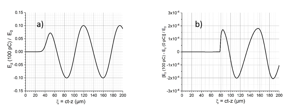
From these results, we can conclude that, in our conditions the beam loading effect can be neglected. Note that in a WAKE-EP calculation, when including the beam loading effect, the computing time increases by nearly a factor of five, because one needs a high number of macro-particles in order to reduce the numerical noise. Without beam loading, the electrons trajectories can be calculated in a fixed external field, which can be determined independently. This favorable feature has been implemented in the numerical code WakeTraj in which the calculation of the electrons trajectories is performed through a post-treatment of one WAKE-EP calculation. Practically, during a WAKE-EP calculation, tables of values of the field amplitude on a grid are periodically save on disk. A WakeTraj calculation will use these tables to extrapolate the field values at the electron positions. In the quasi-linear regime, the typical length of variation of the field amplitude during propagation is given by , which is rather large (1 cm in our case). We have verified that with a propagation length of , between two disk records, we get nearly no-difference between the WAKE-EP and the WakeTraj results. In WakeTraj, there is also the possibility to determine the electric field by applying linear theory formulas [3], allowing to quantify the contribution of non-linear effects, as it will be discussed in the next section.
3 Results of parametric studies
3.1 Optimization of the LPA
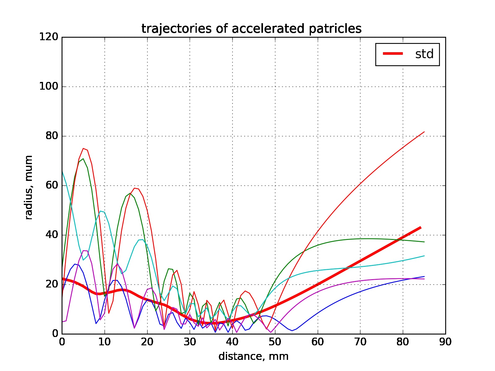
Our three main criteria for optimizing the electron plasma interaction process is to obtain the largest amount of trapped electrons, with the highest energy and the minimum energy spread. This is accomplished by starting the interaction process well before the laser focal plane, where the longitudnal plasma field is relatively small, but the transverse one is large enough to focus the electron bunch. This is illustrated in Fig. 2, in which few electrons trajectories are represented, for a laser focal plane situated at 3 cm of the plasma entrance. We observe first that even electrons with a relatively large initial radius can be captured by the plasma wave. This is due to the fact that at 3 cm from the focal plane, the laser waist reaches 160 µm. We observe also that, during the focusing phase, the electrons perform some betatron oscillations, showing that the focusing is not too strong, so that there will be no large increase of the electron emittance. Finally we can also see that at the end of the interaction there is some re-focusing of the electrons due to the transverse part of the plasma field, which yields a reduction of the final divergence.
Although the electron bunch has been efficiently compressed before entering the plasma (see [2]) its duration should be reduced before being accelerated by the highest fields close to the focal plane. Therefore, the focusing phase is also used to realize a phase rotation in the plane , with , being the position on the laser axis, the duration of propagation and the electron momentum, which value is, in our relativistic regime, close to the Lorentz factor .
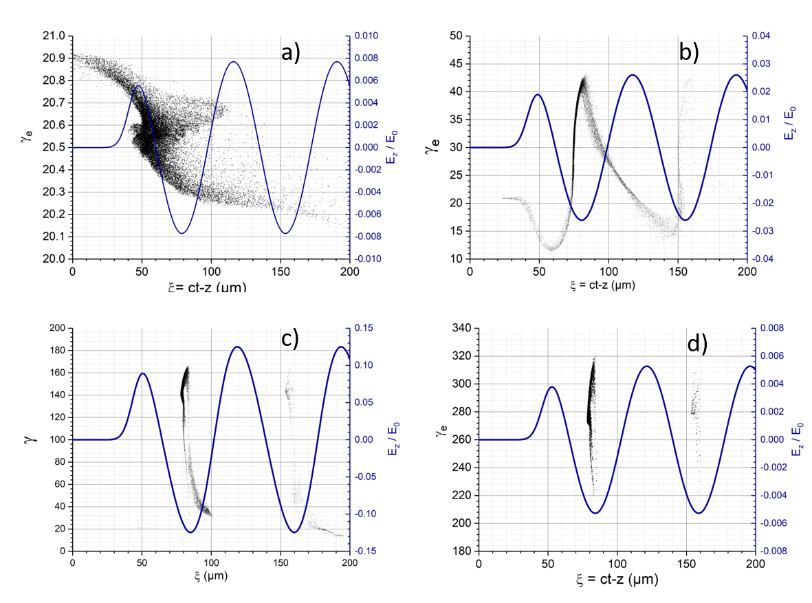
In Fig. 3, is reported the phase space ( of the electron (left axis) together with the values of (right axis) at four different positions. The front part of the laser is at . At the entrance of the plasma (Fig.3-a), and at the central position of the bunch the longitudinal field is close to 0, which corresponds to a maximum of the focusing transverse field. Note that positive values of correspond to an accelerating field, while the transverse field has a difference of phase of with it. The first half period behind the laser is focusing, and the second one defocusing. We observe that around its central part, the electron bunch has a relatively long tail. A part of this tail, interacting with a defocusing field will be lost, a second small part will be trapped in the second period. After 2 cm of propagation (Fig.3-b), some rotation of the phase space has occurred, reducing the duration of the main part of the bunch. We see that the bunch is situated close to the back of the first period, where the accelerating field is maximum and its derivative is minimum. At the focal plane, ( Fig.3-c)) here situated 4 cm from the plasma entrance, a short bunch of high energy electrons is clearly identified. As this bunch is situated at a position where the variation of is small, this bunch will be further accelerated up to the plasma exit with a small increase of his energy spread, as seen in ( Fig.3-d). Emittance of the injected electron bunch at the plasma entrance are mm*mrad, mm*mrad, the emittance at the exit of the plasma mm*mrad, mm*mrad for the horizontal and vertical planes respectively. One of the reasons of the emittance growth is related to multi-bunching, which takes place during the electrons capturing and acceleration by consecutive periods of wake field (See Fig.3-d).
As can been seen from the results of Fig.3 the focusing phase has a strong influence on the final properties of the bunch electrons. For a given configuration two parameters can be used to control the dynamics of the electrons in this phase: the laser focal plane position and the delay between the incoming electron bunch and the laser pulse. These two points are investigated in the next two sections.
3.2 Influence of the laser focal plane position
In this sub-section we analyze the influence of the focal plane position. Test electron bunch of about 20% longer than the plasma wavelength is used in order to uniformly fill the plasma period with electrons and reduce the sensitivity of the results to the delay between the laser and the electron bunch, which is discussed in the next section 3.3. In Fig. 4 are represented the energy distribution of the electrons at the exit of the plasma cell for a focal plane distance from the entrance of the plasma ranging from 1 cm up to 4 cm. The total plasma cell length is fixed to be 9 cm, the delay between the laser and the electron bunch is kept fixed. Although the largest accelerating fields are obtained close to the focal plane, we observe a significant modification of the energy at the peak of the distribution even at distances of several This can be explained by looking at the ratio between the focusing and the dephasing lengths. is defined as the required transport distance so as to change the relative distance between the laser and the electron by that is to go from the position where the accelerating field is zero up to the point where it is maximum. At 10 MeV, cm. Starting at large distances, , the electrons have the time, before being strongly accelerated, to slip up to the position of maximum accelerating field, at it was observed in Fig. 3(b-c). However, if this distance is too large, a significant part of the electrons, in the back of the bunch, will go into the defocusing zone and will be lost. In this case the final energy distribution is rather sharp, but the accelerated charge is reduced. This is the case of the blue curve in Fig. 4, corresponding to a focal plane at 4 cm of the cell entrance. On contrary, if we start close to the focal plane, the electrons are quickly accelerated before changing their relative positions. As they are not initially situated at the maximum of the accelerating field, the final acceleration will be lower. Furthermore, the phase rotation mentioned in the previous sub-section cannot occur, yielding a large energy spread, as observed in the black curve of 4 corresponding to a 1 cm distance of the focal plane.

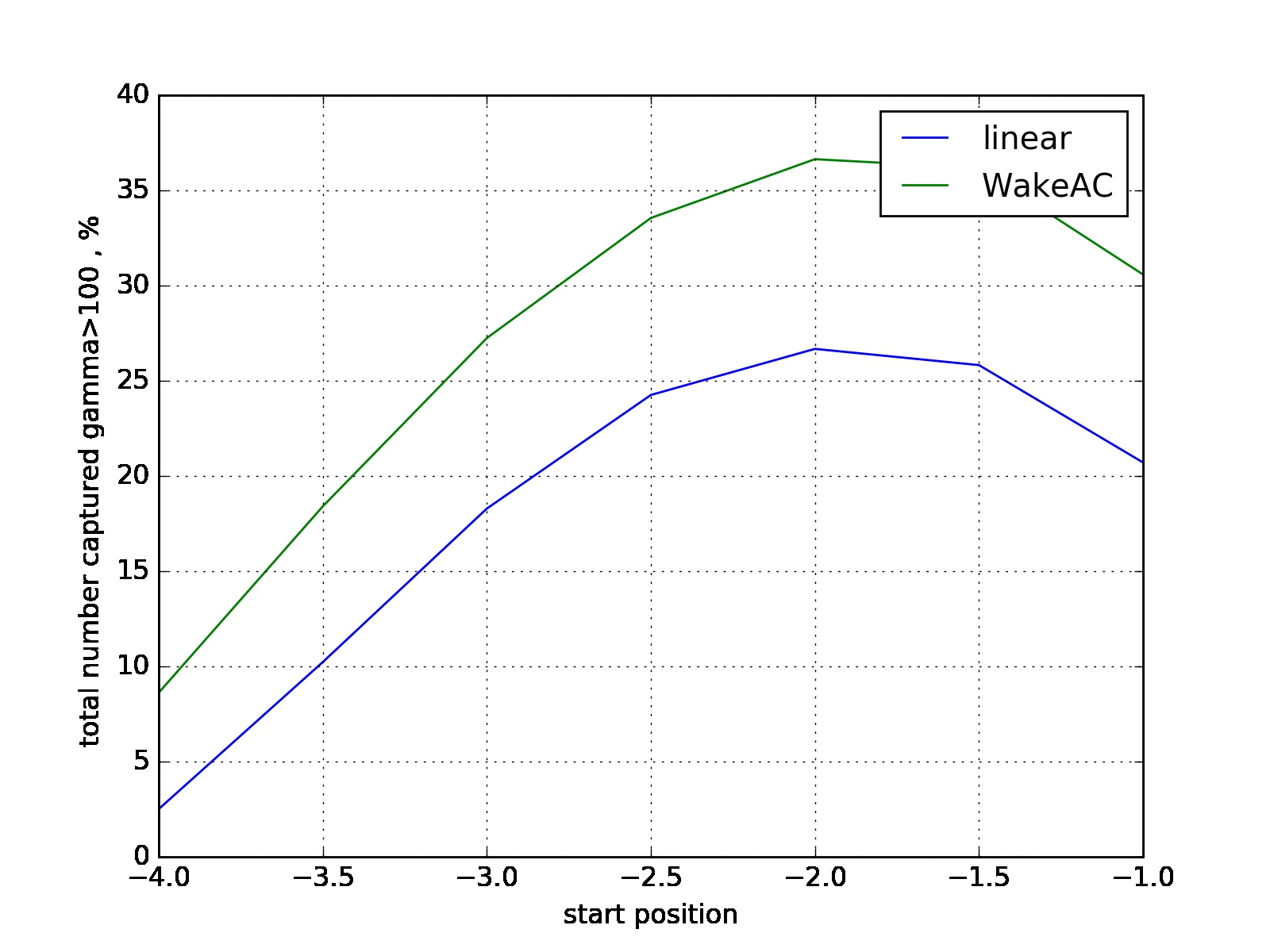
In order to analyze the importance of the non-linear effects the same calculations were also performed using the linear expression of the electric field. In Fig. 5 are represented the percentage of electron accelerated at , calculated by the WakeTraj code using either the WAKE-EP electric field or the linear theory one. We can observe a significant difference between the two results. In fact, in our case, non-linear effects lead to a slight increase of the dimension of the accelerating zone, which increases the amount of trapped electrons and also their energies. This increase is larger at large values of when the percentage of captured electrons is the smallest. In Fig. 5, we observe also that the amount of accelerated charge is decreasing when the plasma entrance becomes close to the focal plane. This is due to the fact that, close to the focal plane, the waist of the laser has its lowest value, as a consequence, electrons with the largest radius can no more be trapped.
3.3 Influence of the delay between the laser and the electron bunch
In Fig. 4 we can observe that the energy spread is decreasing when is increased. Further optimization requires to increase also the amount of accelerated electrons. A first step has been performed through an additional compression of the electron bunch, as obtained in the fully optimized configuration of the ESCULAP beam line described in [2]. The second step relies on a careful optimization of the delay between the maximum amplitude of the laser and the maximum of the electron bunch density. This delay has been modified between 14 and 93 fs. A summary of the obtained results is reported in Table 1 for an injected charge of 10 pC. From this table we see that the reduction of the bunch duration together with an optimization of the delay provide a very strong increase of the accelerated charge reaching up to 86 % of the injected one, with an rms energy spread as low as 4.1 %, a duration that has be reduced by a factor 10 and a divergence around two mrad.
| delay | charge | <> | |||
|---|---|---|---|---|---|
| fs | pC | MeV | % | mrad | fs |
| 13.85 | 8.6 | 139.5 | 5 | 2.4 | 5.2 |
| 23.76 | 8.4 | 140.7 | 4.5 | 2.2 | 6.0 |
| 33.67 | 8.3 | 141.8 | 4.2 | 1.9 | 6.7 |
| 43.57 | 8.2 | 142.6 | 4.1 | 1.8 | 7.5 |
| 53.48 | 7.9 | 143 | 4.2 | 1.7 | 7.5 |
| 63.39 | 7.6 | 143.7 | 4.4 | 1.6 | 7.1 |
| 73.30 | 7.1 | 144.6 | 4.6 | 1.6 | 6.9 |
| 83.21 | 6.6 | 146.1 | 4.9 | 1.7 | 7.8 |
| 93.12 | 5.9 | 147.4 | 5.0 | 1.7 | 8.5 |
In Fig. 6 is reported the energy spectrum of the accelerated bunch for a delay of 43.57 fs. We observe a very sharp peak, with a maximum value of 2 pC/MeV and a relative FWHM width of only 2 %.

4 Conclusion
A parametric study of the laser plasma acceleration process have been performed within the framework of the ESCULAP project. This has been done using the numerical code WakeTraj, which allows through very fast numerical calculations to investigate the influence of several parameters. Results concerning the laser focal plane position and the delay between the laser and the electrons bunch have presented. From these results an optimized configuration has been found which leads to an efficient coupling between the 10 pC, 10 MeV electron bunch and the plasma wave generated by the 2 J LASERIX laser. Using a 9 cm long gas cell more than 75 % of the bunch electrons can be trapped in the plasma wave and accelerated up to an average energy close to 150 MeV, with a dispersion in energy as small as 4 % a divergence of 1.7 mrad and a duration of 7.5 fs, which offers interesting perspectives, in particular for further acceleration in a guiding structure.
Références
- [1] E. Baynard, C. Bruni, K. Cassou, V. Chaumat, N. Delerue, J. Demailly, D. douillet, N. El Kamchi, D. Garzella, O. Guilbaud, S. Jenzer, S. Kazamias, V. Kubytskyi, P. Lepercq, G. Lucas, O. Neveu, M. Pittman, R. Prazeres, H. Purvar, D. Ros, K. Wang, The esculap project at orsay: External injection of low energy electrons in a plasma., in: these proceedings, 2017.
- [2] K. Wang, E. Baynard, C. Bruni, K. Cassou, V. Chaumat, N. Delerue, J. Demailly, D. douillet, N. El Kamchi, D. Garzella, O. Guilbaud, S. Jenzer, S. Kazamias, V. Kubytskyi, P. Lepercq, G. Lucas, O. Neveu, M. Pittman, R. Prazeres, H. Purvar, D. Ros, Longitudinal compression and transverse matching of electron bunch for external injection lpwa at esculap, in: these proceedings, 2017.
-
[3]
E. Esarey, C. B. Schroeder, W. P. Leemans,
Physics of
laser-driven plasma-based electron accelerators, Reviews of Modern Physics
81 (3) (2009) 1229–1285.
doi:10.1103/RevModPhys.81.1229.
URL http://link.aps.org/doi/10.1103/RevModPhys.81.1229 -
[4]
J. L. Vay, R. Lehe, H. Vincenti, B. B. Godfrey, I. Haber, P. Lee,
Recent
advances in high-performance modeling of plasma-based acceleration using the
full PIC method, Nuclear Instruments and Methods in Physics Research
Section A: Accelerators, Spectrometers, Detectors and Associated Equipment
829 (2016) 353–357.
doi:10.1016/j.nima.2015.12.033.
URL http://www.sciencedirect.com/science/article/pii/S0168900215016046 -
[5]
P. Mora, J. Thomas M. Antonsen,
Kinetic modeling of intense, short
laser pulses propagating in tenuous plasmas, Physics of Plasmas 4 (1) (1997)
217.
doi:10.1063/1.872134.
URL http://dx.doi.org/10.1063/1.872134 - [6] B. S. Paradkar, B. Cros, P. Mora, G. Maynard, Numerical modeling of multi-gev laser wakefield electron acceleration inside a dielectric capillary tube, Physics of Plasmas 20 (2013) 083120.
- [7] S. Morshed, T. M. Antonsen, J. P. Palastro, Efficient simulation of electron trapping in laser and plasma wakefield acceleration, Physics of Plasmas 17 (2010) 063106.