On the Achievability Region of Regenerating Codes for Multiple Erasures
Abstract
We study the problem of centralized exact repair of multiple failures in distributed storage. We describe constructions that achieve a new set of interior points under exact repair. The constructions build upon the layered code construction by Tian et al in [1], designed for exact repair of single failure. We firstly improve upon the layered construction for general system parameters. Then, we extend the improved construction to support the repair of multiple failures, with varying number of helpers. In particular, we prove the optimality of one point on the functional repair tradeoff of multiple failures for some parameters. Finally, considering minimum bandwidth cooperative repair (MBCR) codes as centralized repair codes, we determine explicitly the best achievable region obtained by space-sharing among all known points, including the MBCR point.
I Introduction
Driven by the growth of data-centric applications, efficient data storage and retrieval has become of crucial importance for several service providers. Distributed storage systems (DSS) are currently widely employed for large-scale storage. DSS provide scalable storage and high level of resiliency in the face of server failures. To maintain the desired level of failure tolerance, DSS utilize a replacement mechanism for out-of-access nodes, known also as the repair mechanism, that allows to recover the content of inaccessible/failed nodes. The repair process of a failed node is performed by downloading data from accessible nodes (or a subset thereof) in the system and recovering the lost data. Efficiency of a DSS is determined by two parameters, namely, the overhead required for reliability and the amount of data being transferred for a repair process. The seminal work in [2] proposed a new class of erasure codes, called regenerating codes, that optimally solve the repair bandwidth problem. It is shown in [2] that one can significantly reduce the amount of bandwidth required for repair and the bandwidth decreases as each node stores more information. Regenerating codes, as presented in [2], achieve functional repair. In this case, the replacement nodes are not required to be exact copies of the failed nodes, but the repaired code should satisfy reliability constraints. However, in practice, it is often more desirable to recover the exact same information as the failed node, which is called exact repair. Exact repair codes are easier to implement and maintain, and thus are of more interest.
There has been a flurry of interest in designing exact repair regenerating codes [3, 4, 5, 6, 7, 8, 9, 10, 11]. Moreover, there is a growing literature focused on understanding the fundamental limits of exact repair regenerating codes [12, 13, 14, 15], as opposed to the well-understood functional regenerating codes [2].
I-A Multi-node recovery
In many practical scenarios, such as in large scale storage systems, multiple failures are more frequent than a single failure. Moreover, many systems apply a lazy repair strategy, which seeks to limit the repair cost of erasure codes. Indeed, it has been demonstrated that jointly repairing multiple failures reduces the overall bandwidth compared to repairing each failure individually [16, 17, 18, 19]. We distinguish between two ways of repairing multiple failures.
Cooperative regenerating codes: In this framework, each replacement node first downloads information from nodes (helpers). Then, the replacement nodes exchange information between themselves before regenerating the lost nodes. Of interest to our work, we note that codes corresponding to the extreme points on the cooperative tradeoff have been developed: minimum storage cooperative regenerating (MSCR) codes [20, 17] and minimum bandwidth cooperative regeneration (MBCR) codes[21].
Centralized regenerating codes: Upon failure of nodes, the repair is carried out in a centralized way by contacting any helpers out of the available nodes, , and downloading amount of information from each helper. The content of any out of nodes in the system is sufficient to reconstruct the entire data. Let be the size of each node, and be the size of the entire data. A code satisfying the centralized repair constraints is referred to as an code. We also say it is a code of the system. In our previous work [19], we characterized the functional repair tradeoff for multi-node recovery. Let . The normalized functional tradeoff can then be written as follows
| (1) |
where . Inequality (1) gives linear bounds:
| (2) |
In this work, we are interested in designing centralized exact repair regenerating codes for recovering multiple failures. When , the tradeoff reduces to a single point, which is trivially achievable [19]. We hereafter focus on the case .
In [18], it is argued that cooperative regenerative codes can be used to construct centralized repair codes. The total bandwidth in this case is obtained by taking into account the bandwidth obtained from the helper nodes and disregarding the communication between the replacement nodes. In particular, MSCR codes achieve the same performance as centralized minimum storage multi-node repair (MSMR) codes [18, 11]. Additionally, MBCR codes can be used as centralized repair codes, which do not correspond to centralized minimum bandwidth codes on the functional tradeoff [19]. These points are given by
| (3) | ||||
| (4) |
Contributions of the paper: We improve upon the layered construction presented in [1], which is concerned with single node repair, to construct a family of regenerating codes that is capable of repairing multiples failures. In particular, for the system, we first prove the optimality of a particular constructed point using the functional repair tradeoff; combining the achievable points via our construction and also the MBCR point, we then characterize the best achievable region obtained by space-sharing between all known points.
The remainder of the paper is organized as follows. A description of our first code construction is provided in Section II. In Section III, we analyze the achievability region of the system. We describe our second code construction in Section IV, before concluding in Section V.
Notation: we denote by the set of integers for .
II Code Construction
Exact repair regenerating codes are characterized by parameters . We consider a distributed storage system with nodes storing amount of information. The data elements are distributed across the storage nodes such that each node can store up to amount of information. We use to denote the normalized storage size and repair bandwidth, respectively. The system should satisfy the following two properties:
Reconstruction property: by connecting to any nodes it should be sufficient to reconstruct the entire data.
Repair property: upon failure of nodes, a central node is assumed to contact helpers, , and download amount of information from each of them. The exact content of the failed nodes is determined by the central node. is called the repair bandwidth.
We first describe the code construction which is an improvement upon [1]. The construction is based on a collection of subsets of , called a Steiner system. Information is first encoded within each subset, and then distributed among the nodes. We recall the definition of Steiner systems.
Definition 1.
A Steiner system , , is a collection of subsets of size , included in , such that any subset of of size appears exactly once across all the subsets.
Steiner systems do not exist for all design parameters. When , Steiner systems always exist, and the blocks in this case are all combinations of the set . The family of codes we describe below is parameterized by , for , where
| (5) |
Construction 1.
Precoding step: We consider a Steiner system and generate blocks such that each block is indexed by a set . Block corresponds to information symbols over an alphabet of size , which is then encoded using an MSMR code with length and dimension over an alphabet of size . The codeword symbols, called the repair group , is comprised of . Moreover, we assume that the MSMR code possesses the optimal repair bandwidth (3) for any number of erasures , , and any number of helpers , . The total number of information symbols is .
The code matrix: The code structure can be described by a code matrix , of size . The rows of are indexed by integers in , corresponding to the different storage nodes, and its columns are indexed by sets in , arranged in some arbitrary chosen order. We formally define as
| (6) |
where denotes an empty symbol. Node stores all the non-empty symbols of row in the code matrix . It can be checked that the storage per node is given by .
By abuse of notation, the terms block and repair group are used interchangeably. The requirement on the alphabet size is dictated by the existence of an MSMR code with the required property in (3). Such MSMR codes are known to exist [9].
Example 1.
Consider a Steiner system . So the number of blocks is and each node number appears times in the blocks. The 14 blocks are given by
The code matrix is given by (7) in Figure 1.
| (7) |
Let . Then we can repair nodes 1 and 2 simultaneously, by downloading
symbols from nodes 4 and 8, respectively. These help repair symbols and ,
symbols from nodes 5 and 7, respectively. These help repair symbols and ,
symbols from nodes 3 and 6, respectively. These help repair symbols and ,
symbol from each of the nodes and , to repair ,
symbol from each of the nodes and , to repair ,
symbol from each of the nodes and , to repair ,
symbol from each of the nodes and , to repair ,
and similarly for node 2 to repair and .
In total, we download symbols. Each helper transmits symbols.
From the example above, we see that each repair group tolerates the failure of nodes. Therefore, the code also tolerates the failure of up to any nodes. Thus, it can be checked that for Construction 1 from any nodes, we can recover the data, which is the reconstruction parameter. Moreover, the code can recover from any failures. Therefore, it is possible to repair simultaneously any failures. The number of helpers is flexible, and satisfies . The repair bandwidth is given in Propositions 1 and 2 for two different scenarios.
Proposition 1.
Using Construction 1 with , it is possible to repair simultaneously any set of nodes, using helpers, such that the contribution of each helper, denoted by , is given by
| (8) |
Proof:
In the repair procedure, any subset of missing symbols belonging to the same repair group is repaired via MSMR repair procedure, using all available helpers from the same group among the chosen helper nodes. Fixing the set of helper nodes, we argue that the repair is feasible. Indeed, let be the set of helpers. For each repair group , we denote the set of remaining nodes in as . Using and , it follows that
| (9) |
Thus, for each repair group, we have enough information across the set of helpers to recover the missing components.
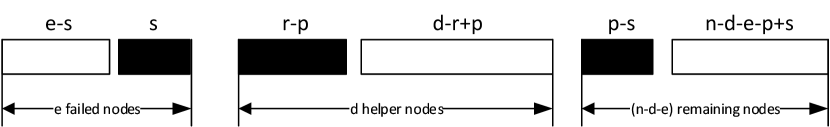
We now analyze the contribution of a single helper : helps in the simultaneous repair of missing symbols of the same repair group, such that . For each size , we count all possible cases in which the repair can be done through the help of coded symbols among all the helpers, because the number of available coded symbols determines the contribution of each helper, as dictated by the MSMR repair bandwidth (3). It follows that, for the corresponding repair group, can be chosen from the set of helpers (helper already belongs to the repair group by assumption), while the remaining elements of the repair group can be chosen from the remaining nodes. Figure 2 summarizes the repair situation for given parameters and . Summing over all repair contributions, and analyzing the limit cases of for a given , (1) follows.
∎
Remark 1.
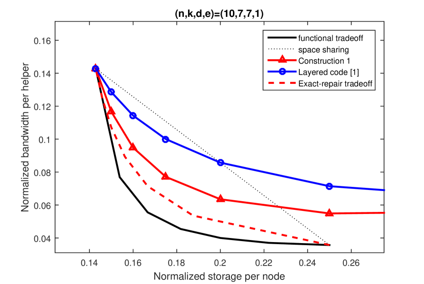
It can be seen that the repair procedure can benefit from the MSMR repair property in the case . In particular, the advantages of using MSMR codes in our construction over maximum distance separable (MDS) codes as in [1] are: 1) lower repair bandwidth, 2) symmetric repair among helper nodes, which obviates the need for the expensive procedure of duplicating the block design as in [1], and 3) adaptability, meaning non-trivial repair strategies for multiple erasures, with the help of varying number of helpers , such that . Figure 3 shows a comparison between the performance of the layered code in [1] and Construction 1, for an system. The MSR repair property clearly helps reduce the bandwidth.
The technique of using MSMR codes as building blocks for outer code constructions has been used in the literature, for instance in constructing codes with local regeneration [22, 23].
Remark 2.
We argue that one can use a regenerating code corresponding to an interior point instead of an MSMR code as the inner code per repair group. Consider the case . Let in (5). The code structure is given by
| (10) |
Thus, the code per column of is of length and dimension . We use the interior code: per repair group. Let be the information size per column. Thus, and . It follows that . To repair node 1, we download a total bandwidth of . Thus, . We obtain the achievable point . The same point is equally achievable using Construction 1 with with an MSMR code as the interior code. This point is optimal on the exact-repair tradeoff of the system [24, 10], and is the optimal point next to the minimum bandwidth regenerating point.
In Proposition 1, we considered Construction 1 with Steiner systems such that . We study next the use of a general Steiner system for the specific ) system.
Proposition 2.
Construction 1 generates an code such that
| (11) | ||||
| (12) |
Proof:
We consider a Steiner system and let . From (5), we obtain and as in (11). To analyze the repair bandwidth per helper, we distinguish two cases:
Case : If the helper node shares a block with both failed nodes, then, by design, does not share any other block with either of the failed nodes. Thus, contributes a single symbol ( bits) that is useful for the repair of the missing symbols of the shared repair group. Otherwise, shares exclusively two blocks with each of the failed nodes. In each of the shared repair group, node contributes symbol ( bits) to help repair the corresponding missing symbol, by virtue of the MSMR repair property (i.e., the missing symbol is repaired with helpers).
Case : For a helper , the number of blocks he shares with both failed nodes is given by The number of blocks node shares exclusively with either of the failed nodes is given by Therefore, the contribution of each helper node is
∎
The repair in Example 1 is an illustration of Proposition 2. Similar to Proposition 1, the repair bandwidth is identical among the helper nodes, and independent of the choice of the failed nodes and helpers.
Remark 3.
We note here that do not depend on by (12). The advantage of using Steiner systems with smaller , whenever they exist, is that they induce smaller and , for the same normalized parameters. Indeed, it can be shown that , as given by (11), is strictly increasing in . Therefore, to reduce the storage size per node, and therefore the repair bandwidth, it is advantageous to use a Steiner System with the smallest , . Moreover, when , Proposition 1 and Proposition 2 give the same .
III Analysis of the achievability for an system
In this section, we analyze the achievable region for an system by means of Construction 1, using, for simplicity, a Steiner system with .
Proposition 3.
Construction 1 with generates a set of achievable points for an system, such that
| (13) | ||||
| (14) |
Proof:
When , is chosen such that , the general expression in (1) is given by
| (15) |
where the last equality follows from Vandermonde’s identity. ∎
III-A Optimality of one achievable point
Proposition 4.
For the system, the point achieved in (13) for is an optimal interior point.
Proof:
From (13) when , we achieve . Thus,
| (16) |
Substituting (16) in (2) and setting , we obtain
Therefore, the above point lies on the functional repair lower bound and hence is optimal. It lies on the first segment of the bound near the MSMR point, and it is not the MSMR point nor the MBCR point, as indicated by (3) and (4). ∎
III-B Optimal extension property
From Proposition 4, Construction 1 gives us an optimal point for any system. Construction 1 also offers the following property.
Proposition 5.
Proof:
Let , for , refer to the parameters of the old and the new systems, respectively. Then, . Moreover, the number of blocks is increased by 1. Let be the index of the new node to be added. The new code is obtained by simply adding another block, whose set is , and adding to the old sets the element to each of them, and thus generating another coded symbol for the corresponding repair group. A key requirement is to assume the use of an MSMR code that can accommodate the addition of extra coded symbols, when needed. This can be done by choosing the number of nodes of the MSMR code to be as large as needed (this may result in an increase in the underlying field size). Each old node will store an extra symbol coming from the new repair group, while the new node stores the newly generated coded symbols from the old repair groups. ∎
Example 2.
We illustrate the process of extending a system to a system. Initially, each repair group is of size 3. The code blocks are given by
The code matrix is given by
Adding node 5 to the system, we add another block , whose symbols will be distributed across the old nodes . The old blocks become
The new node stores newly generated coded symbols of each of the old repair groups . The new code matrix is given by
The above property is useful for systems for which the fault tolerance may be deemed insufficient. Therefore, one can increase the fault tolerance of the system without sacrificing the optimality on the exact repair tradeoff, or changing the existing data. We note also that by a successive application of Proposition 5, we can increase the fault tolerance of the system by any desirable factor.
III-C Acheivability region for the system
In this subsection, we seek to determine the convex hull of the known achievable points for the system. The convex hull, denoted by , is the smallest convex set containing all known achievable points, obtained by all convex combinations (i.e., space-sharing) among the points achieved by Construction 1, described in (14), and also the MBCR point given by (4). The objective is therefore to determine which points are sufficient to describe . We refer to these points as corner points of .
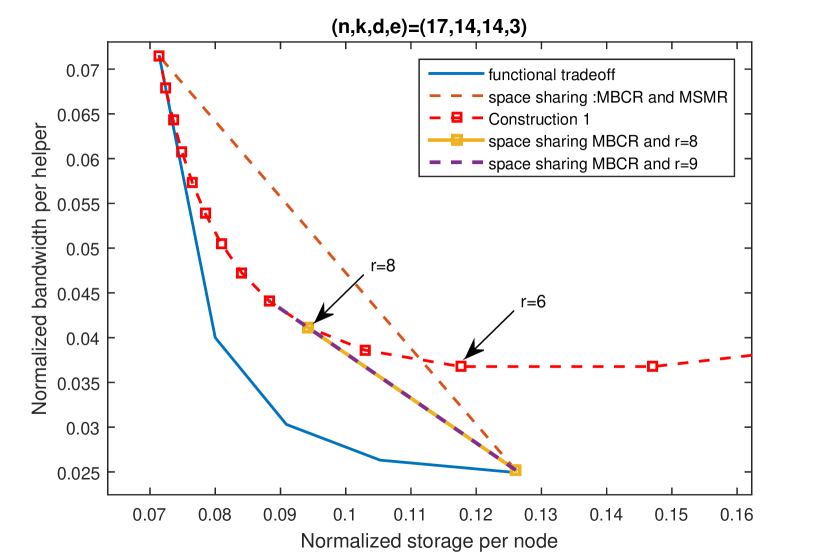
Figure 4 presents the achievable points for an system. The achievable points of (13) are parameterized by , such that . For each , we denote the corresponding point as . As decreases, the storage increases. By abuse of notation, we refer to the point as point . We state some guiding observations for our subsequent analysis. First, one can eliminate some of the achievable points obtained by Construction 1. For instance, point , with , achieves a similar bandwidth as the neighbor point , but at a larger storage size. Points to the right of , such that , can be also immediately eliminated, because they can be outperformed by space-sharing between the MBCR point and some interior point. Interestingly, we observe that point lies exactly on the segment joining point and the MBCR point. This means that, while point is not outperformed by space-sharing, it is nonetheless not necessary for the description of , and thus it is not considered as a corner point. In the following, we show that the observations from Figure 4 can be generalized and we explicitly determine the corner points of , depending on the system’s parameters and .
Lemma 1.
The achievable points in (13), with , are not corner points in .
Proof:
From (13), it can be seen that , seen as a function of , is decreasing. is a fractional function in , with a pole at . For , is convex in . It can be shown that it decreases and then increases monotonically. Therefore, as is decreasing, the points of interest are those for which increases. Moreover, by noticing that , it follows that points with do not contribute to the acheivability region , as these points are outperformed by the point in terms of both, storage and bandwidth. ∎
Lemma 1 implies that it is sufficient to consider the range . We define the non-negative integer such that . We now show that the achievable points can not be eliminated by space-sharing between themselves, when not considering the MBCR point.
Lemma 2.
The achievability region of the points has points with as corner points, when not considering the MBCR point.
Proof:
By virtue of Lemma 1, points with can be eliminated. We consider the segment joining the points and . The slope of the segment, denoted , is given by
The slope is strictly decreasing in for . This means, for any three consecutive points , and , the point lies below the segment joining the other two extreme points. Therefore, space-sharing between and is suboptimal. ∎
Now, we analyze the achievability region when adjoining the MBCR point to the points in (13) with .
Lemma 3.
The MBCR point is a corner point for .
Proof:
Noting that and , along with Lemma 2 concludes the result. ∎
By Lemma 3, we only need to analyze whether space-sharing between the MBCR point and any other point may outperform some of the other achievable points .
Lemma 4.
If a point , , is not outperformed by space-sharing between the point and the MBCR point, then, all points such that , are corner points of the achievability region.
Proof:
The assumption of the lemma implies that the slope of the segment joining the points and is smaller than the slope of the segment between and . As from Lemma 2, the slope of the segment between and is decreasing in , it follows that no point can be outperformed by space-sharing across any two other achievable points, including the MBCR point. ∎
Therefore, to determine the corner points of , we need to successively test for increasing values of , such that , whether the point is outperformed by space-sharing of MBCR and point . Let denote the smallest such that is not outperformed by space-sharing, it follows by Lemma 4 the following achievability region.
Proposition 6.
The achievability region is given by the corner points
| (17) |
where , and is given by
| (18) |
Proof:
Consider . We consider space-sharing between the MBCR point and the point . We compute the normalized bandwidth, denoted by , achieved by the considered space-sharing, at the intermediate point , and then determine whether . Using (14) and (4), we obtain after simplification
| (19) | ||||
| (20) |
We regard as a function of , for fixed and , and as a function of , for fixed and . In this proof, we are interested in analyzing . We analyze in a later proof.
Clearly . Thus, . Therefore, it suffices to study the sign of . We note that implies that point can be eliminated by space-sharing and thus it is a not a corner point. is a quadratic function in . Let denote the discriminant of . It can be checked that
Thus, there exists such that . As the leading coefficient of is positive, and , it follows that one solution, say , is negative and the other solution is non-negative. That is, and . Then, it follows that , which implies that the set can be eliminated. In particular, is always eliminated. Let , as in (18). Thus, outperforms space-sharing and so do all . As , it follows that , and thus . ∎
Proposition 6 agrees with known particular cases. 1) When , we have and the only eliminated point coincides with the MBCR point, in agreement with [1]. 2) The optimal point in Proposition 4 () is not a corner point for , because of and Proposition 6. Indeed, the point with lies exactly on the segment joining the MBCR and the MSMR point. 3) When , the optimal point in Proposition 4 is a corner point, as .
While Proposition 6 characterizes exactly , it does not give insight into when a particular point is a corner point or not. We focus on the analysis of the sign of in (III-C). is linear in . Depending on the sign of its the leading coefficient , there may exist an integer such that when space sharing enhances the achievability region (i.e., ) and does not enhance it when . That is, a point with the same may be a corner point for some systems and may be not a corner point for other systems, with higher reconstruction parameter .
For example, when , we have . It follows that, for systems with , the point is outperformed by space-sharing. For systems with , the point is a corner point.
The next proposition addresses the cases in which a particular point is a corner point, using a similar argument as the above example.
Proposition 7.
Consider the achievable point , for fixed . Let and . Then, Table I specifies the scenarios in which is a corner point in .
| ✗ | ||
Proof:
We examine . First, we note that when , the point is a corner point for all systems. Indeed, as , we have . It follows that, for a fixed , we need to determine the sign of . We have
| (21) | ||||
| (22) | ||||
| (23) |
We note that RHS of (23) can not be an integer, as otherwise should be an odd integer, implying , which leads to a contradiction as . This also implies that the slope of cannot be 0, for . The maximum value of satisfying (23) is given by
| (24) |
Thus, a point is a corner point for any system such that . For each , the point is a corner point if and only if . From (III-C), Let be the solution to the linear equation . Then, after simplification, we have
| (25) | ||||
| (26) |
As , we have , which also implies that . As , we have , with equality iff . It can be checked from (26) that when , . For , point is not a corner point. As is an integer and is not necessarily an integer, it follows that .
∎
Corollary 1.
For a system with , we have
-
•
in (18) can also be expressed as
(27) (28) -
•
The number of corner points in is given by .
-
•
As a function of , levels out at and its final value is given by .
IV Code construction 2
In this section, we present another family of codes improved upon [1] that encapsulates Construction 1 as a special case.
Let denote the generator matrix after vectorization of the code in (6), with . Every node corresponds to a set of columns of . Different from Construction 1, we allow , hence we may feed dependent symbols to the generator matrix. Let be columns of corresponding to out of the nodes. Let be the submatrix of consisting of the columns of . Then the rank of , denoted by , is independent of the choice of the nodes, and is given by [1]
| (29) |
The maximum amount of information that can be stored in the system, , is upper bounded by , i.e., . For instance, when , it can be checked that .
To generate the dependent symbols, we add another layer of inner code to Construction 1. Moreover, the information symbols are assumed to be over , for the finite field and an appropriately chosen positive integer .
Construction 2.
For an system, similarly to Construction 1, the code construction is parameterized by , such that and (we assume ). For each pair , let be given by (29), . First, the information symbols , , are used to construct a linearized polynomial
| (30) |
The linearized polynomial is then evaluated at elements of to obtain , which when viewed as vectors over , are linearly independent. Finally, the evaluation points are fed to the encoder in Construction 1.
We note that the elements in Construction 1 are defined over an alphabet of size , while the evaluation points are defined over . This difference can be resolved by viewing as vectors over and applying Construction 1 to each of their components. Similarly, the repair is carried out component-wise. The linearized polynomial evaluations are an instance of rank-metric codes. In [1, Proposition 5], it is shown that the use of rank-metric codes guarantees the reconstruction property of the regenerating code. Moreover, [1] shows that when , the symbols can be made independent over . In fact, rank metric codes may be replaced by other linear codes, as long as the reconstruction property is satisfied, so as to reduce the field size [1]. Furthermore, we note that when , the use of rank-metric codes is not needed, and the code obtained is simply the code in Construction 1.
Remark 4.
Construction 2 generalizes the non-canonical construction in [1], which is designed for repairing single erasures. Moreover, the non-canonical construction in [1] is based on MDS codes, rather than MSMR codes, and its repair scheme is based on the naive repair scheme of MDS codes. Finally, non-canonical codes in [1] set , while in Construction 2, takes arbitrary values, such that .
Remark 5.
The repair process in Construction 2 does not take into account the dependency introduced by rank-metric codes among the intermediate symbols. It may be possible to reduce further the repair bandwidth by leveraging such dependency.
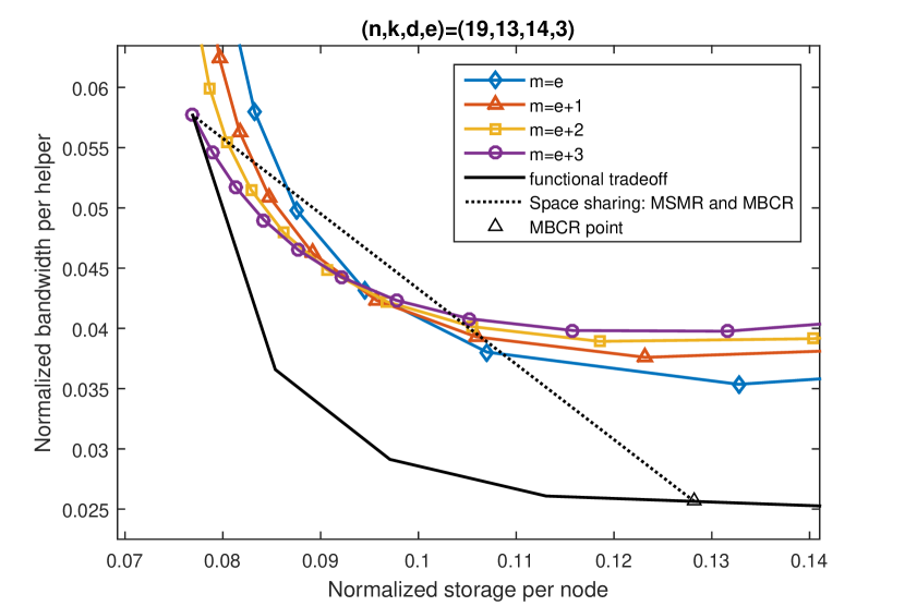
By varying and in Construction 2, we obtain various achievability points. Construction 1 is a special case of Construction 2, corresponding to . In particular, when , Constructions 1 and 2 coincide as . For other parameters, simulation shows that Construction 1 performs better closer to the MSMR point while Construction 2 with performs better closer to the MBCR point. Figure 5 plots the achievable points by Construction 2 for an system, for various values of .
V Conclusion
We studied the problem of centralized exact repair of multiple failures in distributed storage. We first described a construction that achieves a new set of interior points. In particular, we proved the optimality of one point on the functional centralized repair tadeoff. Moreover, considering minimum bandwidth cooperative repair codes as centralized repair codes, we determined explicitly the best achievable region obtained by space-sharing among all known points, for the system. Finally, we described another construction, that includes the first construction as a special case, and that generates various achievable points for a general system. Future work includes investigating outer bounds for the centralized exact repair problem.
References
- [1] C. Tian, B. Sasidharan, V. Aggarwal, V. A. Vaishampayan, and P. V. Kumar, “Layered exact-repair regenerating codes via embedded error correction and block designs,” IEEE Trans. Inf. Theory, vol. 61, no. 4, pp. 1933–1947, 2015.
- [2] A. G. Dimakis, P. Godfrey, Y. Wu, M. J. Wainwright, and K. Ramchandran, “Network coding for distributed storage systems,” IEEE Trans. Inf. Theory, vol. 56, no. 9, pp. 4539–4551, 2010.
- [3] N. B. Shah, K. Rashmi, P. V. Kumar, and K. Ramchandran, “Interference alignment in regenerating codes for distributed storage: Necessity and code constructions,” IEEE Trans. Inf. Theory, vol. 58, no. 4, pp. 2134–2158, 2012.
- [4] C. Suh and K. Ramchandran, “Exact-repair MDS code construction using interference alignment,” IEEE Trans. Inf. Theory, vol. 57, no. 3, pp. 1425–1442, 2011.
- [5] A. S. Rawat, O. O. Koyluoglu, and S. Vishwanath, “Progress on high-rate msr codes: Enabling arbitrary number of helper nodes,” in Information Theory and Applications Workshop (ITA), 2016.
- [6] S. Goparaju, A. Fazeli, and A. Vardy, “Minimum storage regenerating codes for all parameters,” IEEE Trans. Inf. Theory, vol. 63, no. 10, pp. 6318–6328, Oct 2017.
- [7] V. R. Cadambe, S. A. Jafar, H. Maleki, K. Ramchandran, and C. Suh, “Asymptotic interference alignment for optimal repair of MDS codes in distributed storage,” IEEE Trans. Inf. Theory, vol. 59, no. 5, pp. 2974–2987, May 2013.
- [8] I. Tamo, Z. Wang, and J. Bruck, “Zigzag codes: MDS array codes with optimal rebuilding,” IEEE Trans. Inf. Theory, vol. 59, no. 3, pp. 1597–1616, March 2013.
- [9] M. Ye and A. Barg, “Explicit constructions of high-rate MDS array codes with optimal repair bandwidth,” IEEE Trans. Inf. Theory, vol. 63, no. 4, pp. 2001–2014, April 2017.
- [10] M. Elyasi and S. Mohajer, “Determinant coding: A novel framework for exact-repair regenerating codes,” IEEE Trans. Inf. Theory, vol. 62, no. 12, pp. 6683–6697, 2016.
- [11] M. Zorgui and Z. Wang, “Centralized multi-node repair for minimum storage regenerating codes,” in IEEE International Symposium on Information Theory (ISIT), June 2017, pp. 2213–2217.
- [12] B. Sasidharan, K. Senthoor, and P. V. Kumar, “An improved outer bound on the storage-repair-bandwidth tradeoff of exact-repair regenerating codes,” in IEEE International Symposium on Information Theory (ISIT). IEEE, 2014, pp. 2430–2434.
- [13] I. M. Duursma, “Outer bounds for exact repair codes,” arXiv preprint arXiv:1406.4852, 2014.
- [14] B. Sasidharan, N. Prakash, M. N. Krishnan, M. Vajha, K. Senthoor, and P. V. Kumar, “Outer bounds on the storage-repair bandwidth trade-off of exact-repair regenerating codes,” International Journal of Information and Coding Theory, vol. 3, no. 4, pp. 255–298, 2016.
- [15] I. M. Duursma, “Shortened regenerating codes,” arXiv preprint arXiv:1505.00178, 2015.
- [16] A.-M. Kermarrec, N. Le Scouarnec, and G. Straub, “Repairing multiple failures with coordinated and adaptive regenerating codes,” in International Symposium on Network Coding (NetCod). IEEE, 2011, pp. 1–6.
- [17] K. W. Shum and Y. Hu, “Cooperative regenerating codes,” IEEE Trans. Inf. Theory, vol. 59, no. 11, pp. 7229–7258, Nov 2013.
- [18] A. S. Rawat, O. O. Koyluoglu, and S. Vishwanath, “Centralized repair of multiple node failures with applications to communication efficient secret sharing,” arXiv preprint arXiv:1603.04822, 2016.
- [19] M. Zorgui and Z. Wang, “Centralized multi-node repair in distributed storage,” in 2016 54th Annual Allerton Conference on Communication, Control, and Computing (Allerton), Sept 2016, pp. 617–624.
- [20] J. Li and B. Li, “Cooperative repair with minimum-storage regenerating codes for distributed storage,” in INFOCOM, 2014 Proceedings IEEE. IEEE, 2014, pp. 316–324.
- [21] A. Wang and Z. Zhang, “Exact cooperative regenerating codes with minimum-repair-bandwidth for distributed storage,” in 2013 Proceedings IEEE INFOCOM, April 2013, pp. 400–404.
- [22] G. M. Kamath, N. Prakash, V. Lalitha, and P. V. Kumar, “Codes with local regeneration and erasure correction,” IEEE Trans. Inf. Theory, vol. 60, no. 8, pp. 4637–4660, 2014.
- [23] A. S. Rawat, N. Silberstein, O. O. Koyluoglu, and S. Vishwanath, “Optimal locally repairable codes with local minimum storage regeneration via rank-metric codes,” in Information Theory and Applications Workshop (ITA), 2013. IEEE, 2013, pp. 1–8.
- [24] C. Tian, “A note on the rate region of exact-repair regenerating codes,” arXiv preprint arXiv:1503.00011, 2015.