Non-degenerate wavelength computational ghost imaging with thermal light

Deyang Duan, Zhongxiao Man, Yunjie Xia
College of Physics and Engineering, Qufu Normal University, Qufu 273165, China
Shandong Provincial Key Laboratory of Laser Polarization and Information
Technology, Research Institute of Laser, Qufu Normal University, Qufu 273165, China
Corresponding author: duandy2015@qfnu.edu.cn
Abstract

Non-degenerate wavelength computational ghost imaging with thermal light source is studied theoretically and experimentally. The acquired computational ghost images are of high quality when the wavelength of computed light is different from the light detected by bucket detector. Compared to the necessary light of short wavelength in previous ghost imaging, the use of longer wavelength light is demonstrated to bring about ghost images with higher spatial resolution, in strong atmospheric turbulence.

1 Introduction

Ghost imaging is a transverse active-imaging technique that exploits the correlation between two light beams to image an object without spatially resolving measurements of the light beam that has undergone object interaction [1]. Over the past two decades, GI has been found to have some unique advantages over conventional optical imaging technologies, such as super-resolution [2,3], good imaging quality in harsh optical environment [4,5]. Recently, the experiments of GI with X-ray and electronics sources [6-8] have been reported, indicating that GI has become a powerful comprehensive tool in exploring and analyzing the internal characteristics of complex material, e.g. biomolecular structures and nanomaterials.

GI is considered to have broad applied prospects [9-13], especially in remote sensing and laser radar. One of the key reasons that many applications have not yet realized in practice is the complexity of the optical path structure of conventional GI. Fortunately, in 2008, Shapiro proposed a novel GI scheme-computational ghost imaging (CGI)[14], in which the image is reconstructed by correlating a calculated pattern with the signal of a bucket detector located behind the object illuminated by modulated light by spatial light modulator (SLM). Deterministic modulation of a laser beam with an SLM can provide the signal field used for target interrogation, while the on-target intensity pattern needed for the reference field can then be calculated via diffraction theory [15,16].

CGI is currently the most promising imaging solution for remote sensing and laser radar because it has only one optical path, which is different from the conventional GI essentially. Although GI can bring about good imaging quality in harsh optical environment, it is not negligible that the ghost image will be significantly degraded with strong turbulence and large propagation distance. 2011, Meyers et al proposed turbulence-free GI, which played a crucial role in applications [4]. Previous works have shown that the resolution of non-degenerate wavelength GI is higher than that of degenerate wavelength GI [17,18]. In addition, the source with shorter wavelength illuminating the object is effective for ghost images with higher resolution in atmospheric turbulence [19,20].

Non-degenerate wavelength CGI with thermal light source relies on a modification of the conventional CGI set-up (Fig.1). A binocular charge-coupled device (CCD) camera is employed to replace the bucket detector, compared to the conventional CGI scheme. The binocular CCD camera can not only output the bucket signal but also be used as a tool to measure the distance between the SLM and the object [21,22].

2 Theory

In the following, we theoretically illustrate the concept of nondegenerate wavelength CGI with thermal light source. The collected light by the detector is named as signal light, while the calculated patterns by the SLM is named as reference light. To explore the properties of nondegenerate wavelength CGI, a continuous laser beam Essubscript𝐸𝑠E_{s} is projected to an SLM and the modulated light illuminates the object after propagating a distance of z𝑧z in free space. The light field detected by the binocular CCD camera can be expressed as [5,23]

Es​(xs)=βˆ’1Ξ»1​z1​z2β€‹βˆ«π‘‘u​𝑑y​Es′​(Ξ»s,u)​ei​πλs​z1​(yβˆ’u)​T​(y)​ei​πλs​z2​(xsβˆ’y),subscript𝐸𝑠subscriptπ‘₯𝑠1subscriptπœ†1subscript𝑧1subscript𝑧2differential-d𝑒differential-d𝑦superscriptsubscript𝐸𝑠′subscriptπœ†π‘ π‘’superscriptπ‘’π‘–πœ‹subscriptπœ†π‘ subscript𝑧1𝑦𝑒𝑇𝑦superscriptπ‘’π‘–πœ‹subscriptπœ†π‘ subscript𝑧2subscriptπ‘₯𝑠𝑦E_{s}(x_{s})=\frac{-1}{\lambda_{1}\sqrt{z_{1}z_{2}}}\int dudyE_{s}^{{}^{\prime}}\left(\lambda_{s},u\right)e^{\frac{i\pi}{\lambda_{s}z_{1}}\left(y-u\right)}\,T(y)e^{\frac{i\pi}{\lambda_{s}z_{2}}\left(x_{s}-y\right)}, (1)

where T​(y)𝑇𝑦T(y) represents the information of object. The quantities u𝑒u, y𝑦y, xπ‘₯x represent the transverse coordinates of the SLM, the object plane and the bucket detector plane, respectively. z1subscript𝑧1z_{1} is the distance from the SLM to the object. z2subscript𝑧2z_{2} represents the distance from object to the binocular CCD camera.
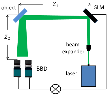
Refer to caption
Figure 1: Setup of the non-degenerate-wavelength computational ghost imaging with thermal light source. SLM: spatial light modulator, BBD: binocular bucket detector.

In practice, z1subscript𝑧1z_{1} and z2subscript𝑧2z_{2} need to be measured in real time to get the calculated light field according to the diffraction principle. Fortunately, the distance from the object to detector can be accurately measured by the binocular parallax principle without adding other equipments [21,22]. For simplicity and practicality, we assume z1=z2=L1subscript𝑧1subscript𝑧2subscript𝐿1z_{1}=z_{2}=L_{1}. In order to obtain a nondegenerate-wavelength computational ghost image, the wavelength of the calculated light E2subscript𝐸2E_{2} should be different from that of the detected light Essubscript𝐸𝑠E_{s}, i.e., Ξ»sβ‰ Ξ»rsubscriptπœ†π‘ subscriptπœ†π‘Ÿ\lambda_{s}\neq\lambda_{r}. Furthermore, the propagation distance L2=z3subscript𝐿2subscript𝑧3L_{2}=z_{3} of the calculated light is determined by the optimal imaging conditions of the non-degenerate GI (Ξ»s​L1=Ξ»r​L2subscriptπœ†π‘ subscript𝐿1subscriptπœ†π‘Ÿsubscript𝐿2\lambda_{s}L_{1}=\lambda_{r}L_{2}) [17]. Thus, the distribution of the computed light is given by

Er​(xr)=(βˆ’iΞ»r​z3)1/2β€‹βˆ«π‘‘u​Er′​(Ξ»r,u)​ei​πλr​z3​(uβˆ’xr).subscriptπΈπ‘Ÿsubscriptπ‘₯π‘Ÿsuperscript𝑖subscriptπœ†π‘Ÿsubscript𝑧312differential-d𝑒superscriptsubscriptπΈπ‘Ÿβ€²subscriptπœ†π‘Ÿπ‘’superscriptπ‘’π‘–πœ‹subscriptπœ†π‘Ÿsubscript𝑧3𝑒subscriptπ‘₯π‘ŸE_{r}(x_{r})=\left(\frac{-i}{\lambda_{r}\sqrt{z_{3}}}\right)^{1/2}\int duE_{r}^{{}^{\prime}}\left(\lambda_{r},u\right)e^{\frac{i\pi}{\lambda_{r}z_{3}}\left(u-x_{r}\right)}\,. (2)

In order to reconstruct the image, the calculated patterns at the object plane are cross-correlated with the signal output by the detector, i.e.,

G​(xs,xr)=⟨Is​(xs)​Ir​(xr)βŸ©βˆ’βŸ¨Is​(xs)βŸ©β€‹βŸ¨Ir​(xr)⟩𝐺subscriptπ‘₯𝑠subscriptπ‘₯π‘Ÿdelimited-⟨⟩subscript𝐼𝑠subscriptπ‘₯𝑠subscriptπΌπ‘Ÿsubscriptπ‘₯π‘Ÿdelimited-⟨⟩subscript𝐼𝑠subscriptπ‘₯𝑠delimited-⟨⟩subscriptπΌπ‘Ÿsubscriptπ‘₯π‘Ÿ\displaystyle G(x_{s},x_{r})=\left\langle I_{s}\left(x_{s}\right)I_{r}\left(x_{r}\right)\right\rangle-\left\langle I_{s}\left(x_{s}\right)\right\rangle\left\langle I_{r}\left(x_{r}\right)\right\rangle
=⟨Esβˆ—β€‹(xs)​Es​(xs)​Erβˆ—β€‹(xr)​Er​(xr)βŸ©βˆ’βŸ¨Esβˆ—β€‹(xs)​Es​(xs)βŸ©β€‹βŸ¨Erβˆ—β€‹(xr)​Er​(xr)⟩absentdelimited-⟨⟩superscriptsubscriptπΈπ‘ βˆ—subscriptπ‘₯𝑠subscript𝐸𝑠subscriptπ‘₯𝑠superscriptsubscriptπΈπ‘Ÿβˆ—subscriptπ‘₯π‘ŸsubscriptπΈπ‘Ÿsubscriptπ‘₯π‘Ÿdelimited-⟨⟩superscriptsubscriptπΈπ‘ βˆ—subscriptπ‘₯𝑠subscript𝐸𝑠subscriptπ‘₯𝑠delimited-⟨⟩superscriptsubscriptπΈπ‘Ÿβˆ—subscriptπ‘₯π‘ŸsubscriptπΈπ‘Ÿsubscriptπ‘₯π‘Ÿ\displaystyle=\left\langle E_{s}^{\ast}\left(x_{s}\right)E_{s}\left(x_{s}\right)E_{r}^{\ast}\left(x_{r}\right)E_{r}\left(x_{r}\right)\right\rangle-\left\langle E_{s}^{\ast}\left(x_{s}\right)E_{s}\left(x_{s}\right)\right\rangle\left\langle E_{r}^{\ast}\left(x_{r}\right)E_{r}\left(x_{r}\right)\right\rangle
=1Ξ»s2​λr​z1​z2​z3β€‹βˆ«π‘‘u1​𝑑u1′​𝑑u2​𝑑u2′​𝑑y​𝑑y′​C​(Ξ»s,Ξ»r;u1,u1β€²,u2,u2β€²)​T​(y)​Tβˆ—β€‹(y)absent1superscriptsubscriptπœ†π‘ 2subscriptπœ†π‘Ÿsubscript𝑧1subscript𝑧2subscript𝑧3differential-dsubscript𝑒1differential-dsuperscriptsubscript𝑒1β€²differential-dsubscript𝑒2differential-dsuperscriptsubscript𝑒2β€²differential-d𝑦differential-dsuperscript𝑦′𝐢subscriptπœ†π‘ subscriptπœ†π‘Ÿsubscript𝑒1superscriptsubscript𝑒1β€²subscript𝑒2superscriptsubscript𝑒2′𝑇𝑦superscriptπ‘‡βˆ—π‘¦\displaystyle=\frac{1}{\lambda_{s}^{2}\lambda_{r}z_{1}z_{2}z_{3}}\int du_{1}du_{1}^{{}^{\prime}}du_{2}du_{2}^{{}^{\prime}}dydy^{{}^{\prime}}C\left(\lambda_{s},\lambda_{r};u_{1},u_{1}^{{}^{\prime}},u_{2},u_{2}^{{}^{\prime}}\right)T(y)T^{\ast}(y) (3)
Γ—ei​πλs​z1​[(yβˆ’u1)2βˆ’(yβ€²βˆ’u1β€²)2]​ei​πλs​z2​[(xsβˆ’y)2βˆ’(xsβ€²βˆ’yβ€²β€²)2]​ei​πλr​z3​[(u2βˆ’xr)2βˆ’(u2β€²βˆ’xrβ€²)2],absentsuperscriptπ‘’π‘–πœ‹subscriptπœ†π‘ subscript𝑧1delimited-[]superscript𝑦subscript𝑒12superscriptsuperscript𝑦′superscriptsubscript𝑒1β€²2superscriptπ‘’π‘–πœ‹subscriptπœ†π‘ subscript𝑧2delimited-[]superscriptsubscriptπ‘₯𝑠𝑦2superscriptsuperscriptsubscriptπ‘₯𝑠′superscript𝑦′′2superscriptπ‘’π‘–πœ‹subscriptπœ†π‘Ÿsubscript𝑧3delimited-[]superscriptsubscript𝑒2subscriptπ‘₯π‘Ÿ2superscriptsuperscriptsubscript𝑒2β€²superscriptsubscriptπ‘₯π‘Ÿβ€²2\displaystyle\times e^{\frac{i\pi}{\lambda_{s}z_{1}}\left[\left(y-u_{1}\right)^{2}-\left(y^{{}^{\prime}}-u_{1}^{{}^{\prime}}\right)^{2}\right]}e^{\frac{i\pi}{\lambda_{s}z_{2}}\left[\left(x_{s}-y\right)^{2}-\left(x_{s}^{{}^{\prime}}-y^{{}^{\prime\prime}}\right)^{2}\right]}e^{\frac{i\pi}{\lambda_{r}z_{3}}\left[\left(u_{2}-x_{r}\right)^{2}-\left(u_{2}^{{}^{\prime}}-x_{r}^{{}^{\prime}}\right)^{2}\right]},

where

C​(Ξ»s,Ξ»r;u1,u1β€²,u2,u2β€²)𝐢subscriptπœ†π‘ subscriptπœ†π‘Ÿsubscript𝑒1superscriptsubscript𝑒1β€²subscript𝑒2superscriptsubscript𝑒2β€²\displaystyle C\left(\lambda_{s},\lambda_{r};u_{1},u_{1}^{{}^{\prime}},u_{2},u_{2}^{{}^{\prime}}\right)
=⟨Esβˆ—β€²β€‹(Ξ»s,u1)​Es′​(Ξ»s,u1β€²)​Erβˆ—β€²β€‹(Ξ»r,u2)​Er′​(Ξ»r,u2β€²)⟩\displaystyle=\left\langle E_{s}^{{}^{\prime}\ast}\left(\lambda_{s},u_{1}\right)E_{s}^{{}^{\prime}}\left(\lambda_{s},u_{1}^{{}^{\prime}}\right)E_{r}^{{}^{\prime}\ast}\left(\lambda_{r},u_{2}\right)E_{r}^{{}^{\prime}}\left(\lambda_{r},u_{2}^{{}^{\prime}}\right)\right\rangle (4)
=⟨Esβˆ—β€²β€‹(Ξ»s)​Es′​(Ξ»s)βŸ©β€‹βŸ¨Erβˆ—β€²β€‹(Ξ»r)​Er′​(Ξ»r)βŸ©β€‹βŸ¨V​(u1)​Vβˆ—β€‹(u2β€²)βŸ©β€‹βŸ¨V​(u2)​Vβˆ—β€‹(u1β€²)⟩\displaystyle=\left\langle E_{s}^{{}^{\prime}\ast}\left(\lambda_{s}\right)E_{s}^{{}^{\prime}}\left(\lambda_{s}\right)\right\rangle\left\langle E_{r}^{{}^{\prime}\ast}\left(\lambda_{r}\right)E_{r}^{{}^{\prime}}\left(\lambda_{r}\right)\right\rangle\left\langle V\left(u_{1}\right)V^{\ast}\left(u_{2}^{{}^{\prime}}\right)\right\rangle\left\langle V\left(u_{2}\right)V^{\ast}\left(u_{1}^{{}^{\prime}}\right)\right\rangle

is the intensity cross-correlation function of the light beams in the spatial and temporal frequency domain evaluated at the output plane of the SLM. Ea​(Ξ»a,ua)=Ea′​(Ξ»a)​V​(ua)subscriptπΈπ‘Žsubscriptπœ†π‘Žsubscriptπ‘’π‘ŽsuperscriptsubscriptπΈπ‘Žβ€²subscriptπœ†π‘Žπ‘‰subscriptπ‘’π‘ŽE_{a}\left(\lambda_{a},u_{a}\right)=E_{a}^{{}^{\prime}}\left(\lambda_{a}\right)V\left(u_{a}\right), a=s,rπ‘Žπ‘ π‘Ÿa=s,r. Esβ€²superscriptsubscript𝐸𝑠′E_{s}^{{}^{\prime}} and Erβ€²superscriptsubscriptπΈπ‘Ÿβ€²E_{r}^{{}^{\prime}} are the independent light fields at the input plane of the SLM. In order to simplify the calculation, we assume that ⟨Eβˆ—β€‹(Ξ»)​E​(Ξ»)⟩=I0=1delimited-⟨⟩superscriptπΈβˆ—πœ†πΈπœ†subscript𝐼01\left\langle E^{\ast}\left(\lambda\right)E\left(\lambda\right)\right\rangle=I_{0}=1. In addition, the SLM mask function V​(u)𝑉𝑒V\left(u\right) possesses spatial correlations that follow Gaussian statistics.

⟨V​(u1)​Vβˆ—β€‹(u2β€²)⟩=eβˆ’u12+u12β€²+u22+u22β€²4​ω​eβˆ’(u1βˆ’u2β€²)2+(u2βˆ’u1β€²)22​lc2,\left\langle V\left(u_{1}\right)V^{\ast}\left(u_{2}^{{}^{\prime}}\right)\right\rangle=e^{-\frac{u_{1}^{2}+u_{1}^{{}^{\prime}2}+u_{2}^{2}+u_{2}^{{}^{\prime}2}}{4\omega}}e^{-\frac{\left(u_{1}-u_{2}^{{}^{\prime}}\right)^{2}+\left(u_{2}-u_{1}^{{}^{\prime}}\right)^{2}}{2l_{c}^{2}}}, (5)

where Ο‰πœ”\omega is the transverse size of the laser beam and lcsubscript𝑙𝑐l_{c} is the correlation parameter of the random amplitude caused by the SLM. Substituting Eq.(5) into Eq.(3), we can thus write the ghost image of Eq.(3) as

G​(xr)=Ο€2Ξ»s​λr​z1​z3​A​B​C​Dβ€‹βˆ«π‘‘y​O​(y)​exp⁑(S24​A+P24​B+Q24​C+R24​D),𝐺subscriptπ‘₯π‘Ÿsuperscriptπœ‹2subscriptπœ†π‘ subscriptπœ†π‘Ÿsubscript𝑧1subscript𝑧3𝐴𝐡𝐢𝐷differential-d𝑦𝑂𝑦superscript𝑆24𝐴superscript𝑃24𝐡superscript𝑄24𝐢superscript𝑅24𝐷G(x_{r})=\frac{\pi^{2}}{\lambda_{s}\lambda_{r}z_{1}z_{3}\sqrt{ABCD}}\int dyO\left(y\right)\exp\left(\frac{S^{2}}{4A}+\frac{P^{2}}{4B}+\frac{Q^{2}}{4C}+\frac{R^{2}}{4D}\right), (6)

where,

A𝐴\displaystyle A =14​ω2+12​lc2βˆ’i​πλs​z1,B=14​ω2+12​lc2+i​πλs​z1,formulae-sequenceabsent14superscriptπœ”212superscriptsubscript𝑙𝑐2π‘–πœ‹subscriptπœ†π‘ subscript𝑧1𝐡14superscriptπœ”212superscriptsubscript𝑙𝑐2π‘–πœ‹subscriptπœ†π‘ subscript𝑧1\displaystyle=\frac{1}{4\omega^{2}}+\frac{1}{2l_{c}^{2}}-\frac{i\pi}{\lambda_{s}z_{1}},B=\frac{1}{4\omega^{2}}+\frac{1}{2l_{c}^{2}}+\frac{i\pi}{\lambda_{s}z_{1}},
C𝐢\displaystyle C =14​ω2+12​lc2βˆ’i​πλr​z3βˆ’14​B​lc4,D=14​ω2+12​lc2+i​πλr​z3βˆ’14​A​lc4,formulae-sequenceabsent14superscriptπœ”212superscriptsubscript𝑙𝑐2π‘–πœ‹subscriptπœ†π‘Ÿsubscript𝑧314𝐡superscriptsubscript𝑙𝑐4𝐷14superscriptπœ”212superscriptsubscript𝑙𝑐2π‘–πœ‹subscriptπœ†π‘Ÿsubscript𝑧314𝐴superscriptsubscript𝑙𝑐4\displaystyle=\frac{1}{4\omega^{2}}+\frac{1}{2l_{c}^{2}}-\frac{i\pi}{\lambda_{r}z_{3}}-\frac{1}{4Bl_{c}^{4}},D=\frac{1}{4\omega^{2}}+\frac{1}{2l_{c}^{2}}+\frac{i\pi}{\lambda_{r}z_{3}}-\frac{1}{4Al_{c}^{4}},
S𝑆\displaystyle S =2​i​π​yΞ»s​z1,P=2​i​π​yΞ»s​z1,Q=i​π​yB​lc2​λs​z1βˆ’2​i​π​x2Ξ»r​z3,R=2​i​π​x2Ξ»r​z3βˆ’i​π​yA​lc2​λs​z1,formulae-sequenceabsent2π‘–πœ‹π‘¦subscriptπœ†π‘ subscript𝑧1formulae-sequence𝑃2π‘–πœ‹π‘¦subscriptπœ†π‘ subscript𝑧1formulae-sequenceπ‘„π‘–πœ‹π‘¦π΅superscriptsubscript𝑙𝑐2subscriptπœ†π‘ subscript𝑧12π‘–πœ‹subscriptπ‘₯2subscriptπœ†π‘Ÿsubscript𝑧3𝑅2π‘–πœ‹subscriptπ‘₯2subscriptπœ†π‘Ÿsubscript𝑧3π‘–πœ‹π‘¦π΄superscriptsubscript𝑙𝑐2subscriptπœ†π‘ subscript𝑧1\displaystyle=\frac{2i\pi y}{\lambda_{s}z_{1}},P=\frac{2i\pi y}{\lambda_{s}z_{1}},Q=\frac{i\pi y}{Bl_{c}^{2}\lambda_{s}z_{1}}-\frac{2i\pi x_{2}}{\lambda_{r}z_{3}},R=\frac{2i\pi x_{2}}{\lambda_{r}z_{3}}-\frac{i\pi y}{Al_{c}^{2}\lambda_{s}z_{1}},

⟨T​(y)​Tβˆ—β€‹(y)⟩=Ξ»s​O​(y)​δ​(yβˆ’yβ€²).delimited-βŸ¨βŸ©π‘‡π‘¦superscriptπ‘‡βˆ—π‘¦subscriptπœ†π‘ π‘‚π‘¦π›Ώπ‘¦superscript𝑦′\left\langle T(y)T^{\ast}(y)\right\rangle=\lambda_{s}O\left(y\right)\delta\left(y-y^{{}^{\prime}}\right). From Eq.(6), we can see that the correlation function G​(xr)𝐺subscriptπ‘₯π‘ŸG(x_{r}) has the same form as that of two-color GI [5,17]. Therefore, the non-degenerate wavelength thermal CGI feasible in practice even when the difference of the wavelengths is very large. Different from the two-color GI, as the reference light field is completely calculated, the wavelength can be set arbitrarily,

We calculate the exponential function exp⁑(S24​A+P24​B+Q24​C+R24​D)superscript𝑆24𝐴superscript𝑃24𝐡superscript𝑄24𝐢superscript𝑅24𝐷\exp\left(\frac{S^{2}}{4A}+\frac{P^{2}}{4B}+\frac{Q^{2}}{4C}+\frac{R^{2}}{4D}\right) on the right of Eq.(6), and then give the standard form of GI. This calculation process is simple but cumbersome, so the result is directly given by

G​(xr)=Ο€2Ξ»s​λr​z1​z3​A​B​C​D​exp⁑(βˆ’xs22​Wf​o​v2)β€‹βˆ«π‘‘y​O​(y)​exp⁑(βˆ’(yβˆ’m​xs2)2​Wp​s​f2),𝐺subscriptπ‘₯π‘Ÿsuperscriptπœ‹2subscriptπœ†π‘ subscriptπœ†π‘Ÿsubscript𝑧1subscript𝑧3𝐴𝐡𝐢𝐷superscriptsubscriptπ‘₯𝑠22superscriptsubscriptπ‘Šπ‘“π‘œπ‘£2differential-dπ‘¦π‘‚π‘¦π‘¦π‘šsuperscriptsubscriptπ‘₯𝑠22superscriptsubscriptπ‘Šπ‘π‘ π‘“2G(x_{r})=\frac{\pi^{2}}{\lambda_{s}\lambda_{r}z_{1}z_{3}\sqrt{ABCD}}\exp\left(-\frac{x_{s}^{2}}{2W_{fov}^{2}}\right)\int dyO\left(y\right)\exp\left(-\frac{\left(y-mx_{s}^{2}\right)}{2W_{psf}^{2}}\right), (7)

where Wf​o​vsubscriptπ‘Šπ‘“π‘œπ‘£W_{fov} and mπ‘šm represent the view of field and magnification factor [5], respectively.

Wp​s​f=R​e​12​(K12+K22+K32+K42)subscriptπ‘Šπ‘π‘ π‘“π‘…π‘’12superscriptsubscript𝐾12superscriptsubscript𝐾22superscriptsubscript𝐾32superscriptsubscript𝐾42W_{psf}=Re\sqrt{\frac{1}{2\left(K_{1}^{2}+K_{2}^{2}+K_{3}^{2}+K_{4}^{2}\right)}} (8)

is the width of point spread function (PSF).

K1subscript𝐾1\displaystyle K_{1} =Ο€A​λs​z1,K2=Ο€B​λs​z1,K3=Ο€2​B​C​λs​z1​lc2,formulae-sequenceabsentπœ‹π΄subscriptπœ†π‘ subscript𝑧1formulae-sequencesubscript𝐾2πœ‹π΅subscriptπœ†π‘ subscript𝑧1subscript𝐾3πœ‹2𝐡𝐢subscriptπœ†π‘ subscript𝑧1superscriptsubscript𝑙𝑐2\displaystyle=\frac{\pi}{\sqrt{A}\lambda_{s}z_{1}},K_{2}=\frac{\pi}{\sqrt{B}\lambda_{s}z_{1}},K_{3}=\frac{\pi}{2B\sqrt{C}\lambda_{s}z_{1}l_{c}^{2}},
K4subscript𝐾4\displaystyle K_{4} =Ο€2​D​λs​z1​(1B​lc2βˆ’1A​lc2).absentπœ‹2𝐷subscriptπœ†π‘ subscript𝑧11𝐡superscriptsubscript𝑙𝑐21𝐴superscriptsubscript𝑙𝑐2\displaystyle=\frac{\pi}{2\sqrt{D}\lambda_{s}z_{1}}\left(\frac{1}{Bl_{c}^{2}}-\frac{1}{Al_{c}^{2}}\right).
Refer to caption
Figure 2: (a) Width of the point-spread function as a function of Ξ»s=800​n​msubscriptπœ†π‘ 800π‘›π‘š\lambda_{s}=800nm, Ξ»r=400,600,800,1000,1200,1400​n​msubscriptπœ†π‘Ÿ400600800100012001400π‘›π‘š\lambda_{r}=400,600,800,1000,1200,1400nm. Parameters used are Ο‰=5​c​mπœ”5π‘π‘š\omega=5cm, lc=1​m​msubscript𝑙𝑐1π‘šπ‘šl_{c}=1mm, z1=1​k​msubscript𝑧11π‘˜π‘šz_{1}=1km. (b)The corresponding plot of PSF as a function of Ξ»s=800​n​msubscriptπœ†π‘ 800π‘›π‘š\lambda_{s}=800nm, Ξ»r=400,600,800,1000,1200,1400​n​msubscriptπœ†π‘Ÿ400600800100012001400π‘›π‘š\lambda_{r}=400,600,800,1000,1200,1400nm.

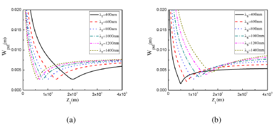
Equation (8) is plotted in Fig.2 as a function of variable Ξ»rsubscriptπœ†π‘Ÿ\lambda_{r}, Ξ»ssubscriptπœ†π‘ \lambda_{s} and L1=z1subscript𝐿1subscript𝑧1L_{1}=z_{1}. It is seen that the width of the PSF attains its smallest value when Ξ»s​L1=Ξ»r​L2subscriptπœ†π‘ subscript𝐿1subscriptπœ†π‘Ÿsubscript𝐿2\lambda_{s}L_{1}=\lambda_{r}L_{2}, in previous work[15]. Fig.2(a) compares the resolution of conventional CGI with single wavelength light source (blue dot line) and nondegenerate wavelength CGI (other kinds of lines), from which we found that there is no significant difference between them (minimum value of PSF). Compared to this one, the spatial resolution changes significantly as the wavelength of signal light changes. This result has illustrated the results that the spatial resolution of non-degenerate wavelength CGI depends more strongly on signal light Ξ»ssubscriptπœ†π‘ \lambda_{s} than reference light Ξ»rsubscriptπœ†π‘Ÿ\lambda_{r} (Fig.2(b)).

In the case of atmospheric turbulence, based on the extended Huygens-Fresnel integral, the propagation function from the source plane to the detector plane is given by [5,23]

Es​(xs)subscript𝐸𝑠subscriptπ‘₯𝑠\displaystyle E_{s}(x_{s}) =βˆ’1Ξ»s​z1​z2β€‹βˆ«π‘‘u​𝑑y​Es′​(Ξ»s,u1)​ei​πλs​z1​(yβˆ’ua)absent1subscriptπœ†π‘ subscript𝑧1subscript𝑧2differential-d𝑒differential-d𝑦superscriptsubscript𝐸𝑠′subscriptπœ†π‘ subscript𝑒1superscriptπ‘’π‘–πœ‹subscriptπœ†π‘ subscript𝑧1𝑦subscriptπ‘’π‘Ž\displaystyle=\frac{-1}{\lambda_{s}\sqrt{z_{1}z_{2}}}\int dudyE_{s}^{{}^{\prime}}\left(\lambda_{s},u_{1}\right)e^{\frac{i\pi}{\lambda_{s}z_{1}}\left(y-u_{a}\right)}\,
Γ—exp⁑[Ο•1​(y,u)]​T​(y)​exp⁑[Ο•2​(x,y)]​T​(y)​ei​πλs​z2​(xsβˆ’y),absentsubscriptitalic-Ο•1𝑦𝑒𝑇𝑦subscriptitalic-Ο•2π‘₯𝑦𝑇𝑦superscriptπ‘’π‘–πœ‹subscriptπœ†π‘ subscript𝑧2subscriptπ‘₯𝑠𝑦\displaystyle\times\exp\left[\phi_{1}(y,u)\right]T(y)\exp\left[\phi_{2}(x,y)\right]T(y)e^{\frac{i\pi}{\lambda_{s}z_{2}}\left(x_{s}-y\right)}, (9)

where Ο•1subscriptitalic-Ο•1\phi_{1} and Ο•2subscriptitalic-Ο•2\phi_{2} characterize the atmospheric turbulence effects in the SLM-to-object path and the object-to-bucket-detector path, respectively. Because the reference arm can be computed by the simulation program according to the diffraction theory, the computed light field is not affected by atmospheric turbulence. Thus, the imaging function of nondegenerate-wavelength CGI with atmospheric turbulence can be expressed as

G​(xr)𝐺subscriptπ‘₯π‘Ÿ\displaystyle G(x_{r}) =Ο€2Ξ»s​λr​z1​z3​A′​B′​C′​D′​exp⁑(βˆ’xs22​Wf​o​v2)absentsuperscriptπœ‹2subscriptπœ†π‘ subscriptπœ†π‘Ÿsubscript𝑧1subscript𝑧3superscript𝐴′superscript𝐡′superscript𝐢′superscript𝐷′superscriptsubscriptπ‘₯𝑠22superscriptsubscriptπ‘Šπ‘“π‘œπ‘£2\displaystyle=\frac{\pi^{2}}{\lambda_{s}\lambda_{r}z_{1}z_{3}\sqrt{A^{{}^{\prime}}B^{{}^{\prime}}C^{{}^{\prime}}D^{{}^{\prime}}}}\exp\left(-\frac{x_{s}^{2}}{2W_{fov}^{2}}\right)
Γ—βˆ«dyO(y)exp(βˆ’(yβˆ’m​xs2)2​Wp​s​f2).\displaystyle\times\int dyO\left(y\right)\exp\left(-\frac{\left(y-mx_{s}^{2}\right)}{2W_{psf}^{2}}\right). (10)

The PSF has the same form as Eq. 8, i.e.,

Wp​s​f=R​e​12​(K12+K22+K32+K42),subscriptπ‘Šπ‘π‘ π‘“π‘…π‘’12superscriptsubscript𝐾12superscriptsubscript𝐾22superscriptsubscript𝐾32superscriptsubscript𝐾42W_{psf}=Re\sqrt{\frac{1}{2\left(K_{1}^{2}+K_{2}^{2}+K_{3}^{2}+K_{4}^{2}\right)}}, (11)

with

Aβ€²superscript𝐴′\displaystyle A^{{}^{\prime}} =14​ω2+12​lc2+12​ρ2βˆ’i​πλs​z1,Bβ€²=14​ω2+12​lc2+12​ρ2+i​πλs​z1βˆ’14​A′​ρ4,formulae-sequenceabsent14superscriptπœ”212superscriptsubscript𝑙𝑐212superscript𝜌2π‘–πœ‹subscriptπœ†π‘ subscript𝑧1superscript𝐡′14superscriptπœ”212superscriptsubscript𝑙𝑐212superscript𝜌2π‘–πœ‹subscriptπœ†π‘ subscript𝑧114superscript𝐴′superscript𝜌4\displaystyle=\frac{1}{4\omega^{2}}+\frac{1}{2l_{c}^{2}}+\frac{1}{2\rho^{2}}-\frac{i\pi}{\lambda_{s}z_{1}},B^{{}^{\prime}}=\frac{1}{4\omega^{2}}+\frac{1}{2l_{c}^{2}}+\frac{1}{2\rho^{2}}+\frac{i\pi}{\lambda_{s}z_{1}}-\frac{1}{4A^{{}^{\prime}}\rho^{4}},
Cβ€²superscript𝐢′\displaystyle C^{{}^{\prime}} =14​ω2+12​lc2+12​ρ2βˆ’i​πλr​z3βˆ’14​B′​lc4absent14superscriptπœ”212superscriptsubscript𝑙𝑐212superscript𝜌2π‘–πœ‹subscriptπœ†π‘Ÿsubscript𝑧314superscript𝐡′superscriptsubscript𝑙𝑐4\displaystyle=\frac{1}{4\omega^{2}}+\frac{1}{2l_{c}^{2}}+\frac{1}{2\rho^{2}}-\frac{i\pi}{\lambda_{r}z_{3}}-\frac{1}{4B^{{}^{\prime}}l_{c}^{4}} (12)
Dβ€²superscript𝐷′\displaystyle D^{{}^{\prime}} =14​ω2+12​lc2+i​πλr​z3βˆ’14​A′​lc2βˆ’116​A2′​B′​lc4​ρ4βˆ’164​A2′​B2′​C′​lc8​ρ4,\displaystyle=\frac{1}{4\omega^{2}}+\frac{1}{2l_{c}^{2}}+\frac{i\pi}{\lambda_{r}z_{3}}-\frac{1}{4A^{{}^{\prime}}l_{c}^{2}}-\frac{1}{16A^{{}^{\prime}2}B^{{}^{\prime}}l_{c}^{4}\rho^{4}}-\frac{1}{64A^{{}^{\prime}2}B^{{}^{\prime}2}C^{{}^{\prime}}l_{c}^{8}\rho^{4}},
K1subscript𝐾1\displaystyle K_{1} =Ο€A′​λs​z1,K2=Ο€B′​λs​z1​(1βˆ’12​A′​ρ2),formulae-sequenceabsentπœ‹superscript𝐴′subscriptπœ†π‘ subscript𝑧1subscript𝐾2πœ‹superscript𝐡′subscriptπœ†π‘ subscript𝑧1112superscript𝐴′superscript𝜌2\displaystyle=\frac{\pi}{\sqrt{A^{{}^{\prime}}}\lambda_{s}z_{1}},K_{2}=\frac{\pi}{\sqrt{B^{{}^{\prime}}}\lambda_{s}z_{1}}\left(1-\frac{1}{2A^{{}^{\prime}}\rho^{2}}\right),
K3subscript𝐾3\displaystyle K_{3} =Ο€2​B′​C′​λs​z1​lc2​(1βˆ’12​A′​ρ2),absentπœ‹2superscript𝐡′superscript𝐢′subscriptπœ†π‘ subscript𝑧1superscriptsubscript𝑙𝑐2112superscript𝐴′superscript𝜌2\displaystyle=\frac{\pi}{2B^{{}^{\prime}}\sqrt{C^{{}^{\prime}}}\lambda_{s}z_{1}l_{c}^{2}}\left(1-\frac{1}{2A^{{}^{\prime}}\rho^{2}}\right),
K4subscript𝐾4\displaystyle K_{4} =Ο€2​D′​λs​z1[βˆ’1A′​lc2+1B′​lc2(1βˆ’12​A′​ρ2)\displaystyle=\frac{\pi}{2\sqrt{D^{{}^{\prime}}}\lambda_{s}z_{1}}\left[-\frac{1}{A^{{}^{\prime}}l_{c}^{2}}+\frac{1}{B^{{}^{\prime}}l_{c}^{2}}\left(1-\frac{1}{2A^{{}^{\prime}}\rho^{2}}\right)\right.
Γ—(12​A′​ρ2+18​A′​B′​C′​lc4​ρ2)],\displaystyle\left.\times\left(\frac{1}{2A^{{}^{\prime}}\rho^{2}}+\frac{1}{8A^{{}^{\prime}}B^{{}^{\prime}}C^{{}^{\prime}}l_{c}^{4}\rho^{2}}\right)\right],

where ρ=(0.55​Cn,s2​ks2​z0)βˆ’35𝜌superscript0.55superscriptsubscript𝐢𝑛𝑠2superscriptsubscriptπ‘˜π‘ 2subscript𝑧035\rho=\left(0.55C_{n,s}^{2}k_{s}^{2}z_{0}\right)^{-\frac{3}{5}}, Cn,s2superscriptsubscript𝐢𝑛𝑠2C_{n,s}^{2} is the turbulence strength.

Refer to caption
Figure 3: The PSF of the nondegenerate wavelength CGI with thermal light source. Parameters used are Ο‰=5​c​mπœ”5π‘π‘š\omega=5cm, lc=1​m​msubscript𝑙𝑐1π‘šπ‘šl_{c}=1mm, z1=1​k​msubscript𝑧11π‘˜π‘šz_{1}=1km. (a-d) are the curve lines for Cn,s2=10βˆ’15superscriptsubscript𝐢𝑛𝑠2superscript1015C_{n,s}^{2}=10^{-15}, 10βˆ’14superscript101410^{-14}, 10βˆ’13superscript101310^{-13}, 10βˆ’12superscript101210^{-12}, Ξ»s=800​n​msubscriptπœ†π‘ 800π‘›π‘š\lambda_{s}=800nm, Ξ»r=400,600,800,1000,1200,1400​n​msubscriptπœ†π‘Ÿ400600800100012001400π‘›π‘š\lambda_{r}=400,600,800,1000,1200,1400nm. (e-h) are the curve lines for Cn,s2=10βˆ’15superscriptsubscript𝐢𝑛𝑠2superscript1015C_{n,s}^{2}=10^{-15}, 10βˆ’14superscript101410^{-14}, 10βˆ’13superscript101310^{-13}, 10βˆ’12superscript101210^{-12}, Ξ»r=800​n​msubscriptπœ†π‘Ÿ800π‘›π‘š\lambda_{r}=800nm, Ξ»s=400,600,800,1000,1200,1400​n​msubscriptπœ†π‘ 400600800100012001400π‘›π‘š\lambda_{s}=400,600,800,1000,1200,1400nm.

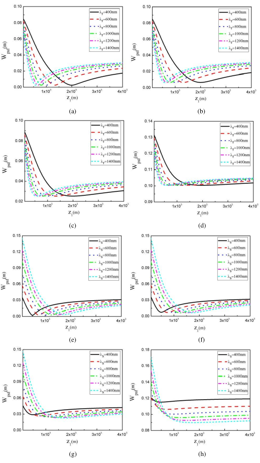
Equation (11) is plotted in Fig.3 as a function of Ξ»rsubscriptπœ†π‘Ÿ\lambda_{r} and Ξ»ssubscriptπœ†π‘ \lambda_{s}. We test the resolution of nondegenerate wavelength thermal CGI with the wavelength Ξ»ssubscriptπœ†π‘ \lambda_{s} fixed and the wavelength Ξ»rsubscriptπœ†π‘Ÿ\lambda_{r} changed. The results are shown in Fig.3(a)-3(d). The results show that the spatial resolution of non-degenerate wavelength CGI with thermal light is equal to that of conventional CGI in tuebulence. The spatial resolution will be reduced with the increase of turbulence. We fix the Ξ»rsubscriptπœ†π‘Ÿ\lambda_{r} and change Ξ»ssubscriptπœ†π‘ \lambda_{s}, the results are shown in Fig.3(e)-3(h). In weak turbulence (Cn,s2=1Γ—10βˆ’15superscriptsubscript𝐢𝑛𝑠21superscript1015C_{n,s}^{2}=1\times 10^{-15}), ghost images with higher resolution can be obtained when the light of signal arm carries shorter wavelength, which is the same as the previous works [5,16,19]. However, in strong turbulence (Cn,s2=1Γ—10βˆ’12superscriptsubscript𝐢𝑛𝑠21superscript1012C_{n,s}^{2}=1\times 10^{-12}), ghost images with higher resolution can be obtained when the light of signal arm carries longer wavelength, which is different from previous works [5,16,19].

3 Experiments

To experimentally demonstrate the non-degenerate wavelength CGI, we used the imaging setup described in the previous section to image a Rubik’s Cube. The setup is based on a two-dimensional amplitude-only ferroelectric liquid crystal spatial light modulator (FLC-SLM, Meadowlark Optics A512-450-850), with 512Γ—512512512512\times 512 addressable 15​μ​mΓ—15​μ​m15πœ‡π‘š15πœ‡π‘š15\mu m\times 15\mu m pixels. The light sources are CW solid-state lasers with wavelength 532nm and 635 nm respectively. The bucket detector is replaced by a binocular camera (CCD) with 640Γ—480640480640\times 480 addressable 3.0​μ​mΓ—3.0​μ​m3.0πœ‡π‘š3.0πœ‡π‘š3.0\mu m\times 3.0\mu m. A 5Γ—5Γ—5​c​m3555𝑐superscriptπ‘š35\times 5\times 5cm^{3} object (Rubik’s Cube) located at a distance L1=100​c​msubscript𝐿1100π‘π‘šL_{1}=100cm from the SLM, and a lens collects the reflected light onto the detector. In each realization a grayscale with 512Γ—512512512512\times 512 is sent to the SLM. The distance between the two detectors of the binocular camera is 12 cm. The measurement error of binocular ranging is about 1%. The accuracy of the measurement can be higher by optimizing the algorithm and calibration.

Refer to caption
Figure 4: The nondegenerate-wavelength computational ghost image with 500000 realizations. (a,e) object,(b-d) Parameters used are Ξ»s=532​n​msubscriptπœ†π‘ 532π‘›π‘š\lambda_{s}=532nm, Ξ»r=400​n​m,532​n​m,635​n​msubscriptπœ†π‘Ÿ400π‘›π‘š532π‘›π‘š635π‘›π‘š\lambda_{r}=400nm,532nm,635nm. (f-h)The corresponding results with Ξ»s=635​n​msubscriptπœ†π‘ 635π‘›π‘š\lambda_{s}=635nm, Ξ»r=400​n​m,532​n​m,635​n​msubscriptπœ†π‘Ÿ400π‘›π‘š532π‘›π‘š635π‘›π‘š\lambda_{r}=400nm,532nm,635nm.

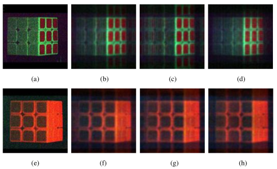
Figure 4 compares the nondegenerate-wavelength CGI with different wavelengths of signal light and reference light. The experiment results show that a high-quality ghost image can be obtained even when the wavelengths of light used in the signal and reference arms are very different. Furthermore, changing the wavelength of the reference light does not significantly improve the resolution of ghost image. The color of non-degenerate wavelength ghost image depends on the light detected by the bucket detector[24,25]. It is noteworthy that the red color in Fig.4(a)-4(d) is produced by laser-activated coatings, which does not affect the experimental results.

Refer to caption
Figure 5: The nondegenerate-wavelength computational ghost image with 500000 realizations. (a,b) object, (c) Parameters used are Ξ»r=Ξ»s=532​n​msubscriptπœ†π‘Ÿsubscriptπœ†π‘ 532π‘›π‘š\lambda_{r}=\lambda_{s}=532nm. (d)The corresponding results with Ξ»r=Ξ»s=635​n​msubscriptπœ†π‘Ÿsubscriptπœ†π‘ 635π‘›π‘š\lambda_{r}=\lambda_{s}=635nm.

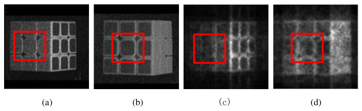
To verify the effect of strong atmospheric turbulence on non-degenerate wavelength CGI, turbulence is introduced by adding heating elements at 550βˆ˜β€‹Csuperscript550C{550}^{\circ}{\rm C}underneath optical path [4]. Heating of the air causes temporal and spatial fluctuations on its index of refraction that makes the classical image of the object jitter about randomly on the image plane causing a β€œblurred” picture. Fig.5 shows that the spatial resolution of ghost image obtained by 635 nm (Fig.5(d)) is better than that of 532 nm (Fig.5(c)). The reason for this phenomenon is that strong turbulence has less effect on long wavelength laser than that on short wavelength laser [26]. Further studies have shown that this conclusion applies to all types of ghost imaging.

4 Discussions and conclusion

Shapiro creatively proposed the concept of CGI based on the modulation of light field by SLM. Compared with conventional GI, the CGI is more suitable for laser radar, remote sensing and other fields. Chan et al. proposed two-color GI based on the modulation effect of spatial light modulator on different wavelength light, and proved that the resolution of ghost image depends on each of these wavelengths in non-degenerate wavelength GI with thermal light [17]. Actually, two-color GI is still a conventional GI rather than CGI. Here, our results show that the resolution of non-degenerate wavelength CGI with thermal light depends primarily on the wavelength used to illuminate the object, but not on the calculated light. It is not difficult to understand that the correlation function of non-degenerate wavelength CGI is the same as that of two-color GI, because they are all based on the modulation of light field by spatial light modulator. Thus, the spatial intensity pattern of the light on the signal arm and computed (reference) arm is the same, which are similar to that of conventional GI [27].

In conclusion, we have shown that nondegenerate wavelength CGI with thermal light source is not only feasible but can also give a ghost image with high quality. The key to nondegenerate wavelength CGI is to use the binocular ranging principle to measure the distance of object in real time to obtain the calculated light field. Moreover, there is no fundamental limit in the extent for the wavelength in the reference arm as the corresponding field is completely calculated. It is out of the restriction of the spatial light modulator, which is better than the conventional two-color GI. More important, the results show that the longer wavelength laser is sent to illuminate the object in strong atmospheric turbulence, the higher resolution of ghost image can be obtained. In addition, this scheme may have potential imaging applications for moving objects, which will be discussed in detail in our future works.

Funding

National Natural Science Foundation of China (11704221, 11574178, 61675115); Natural Science Foundation of Shandong Province (ZR2016AP09, ZR2016JL005); Taishan Scholar Foundation of Shandong Province (tsqn201812059).

Acknowledgments

The authors wish to thank Dongfeng Shi for his contribution to resolution calculation.

References

  • [1] T. B. Pittman, Y. Shih, D. V. Strekalov, and A. V. Sergienko, "Optical imaging by means of two-photon quantum entanglement," Phys. Rev. A 52, R3429–R3432 (1995).
  • [2] H. Wang, S. Han and M. I. Kolobov, "Quantum limits of super-resolution via Sparsity constraint," Opt. Express 20, 23235 (2012).
  • [3] C. Zhang, W. L. Gong and S. S. Han, "Improving imaging resolution of shaking targets by Fourier-transform ghost diffraction," Appl. Phys. Lett. 102, 021111 (2013).
  • [4] R. E. Meyers, K. S. Deacon and Y. Shih, "Turbulence-free ghost imaging," Appl. Phys. Lett. 98, 111115 (2011).
  • [5] D. F. Shi, C. Y. Fan, P. F. Zhang, H. Shen, J. H. Zhang, C. H. Qiao, and Y. J. Wang, "Two-wavelength ghost imaging through atmospheric turbulence," Opt. Express 21(2), 2050-2064 (2013).
  • [6] D. Pelliccia, A. Rack, M. Scheel, V. Cantelli, and D. M. Paganin, "Experimental x-ray ghost imaging," Phys. Rev. Lett. 117,113902 (2016).
  • [7] H. Yu, R. Lu, S. Han, H. Xie. G. Du. T. Xiao, and D. Zhu, "Fourier-transform ghost imaging with hard X rays," Phys. Rev. Lett. 117, 113901 (2016).
  • [8] A. Zhang, Y. He, L. Wu, L. Chen and B. Wang, "Tabletop x-ray ghost imaging with ultra-low radiation," Optica 5(4), 374-377 (2018).
  • [9] M. Bina, D. Magatti, M. Molteni, A. Gatti, L. A. Lugiato and F. Ferri, "Backscattering Differential Ghost Imaging in Turbid Media," Phys. Rev. Lett. 110, 083901 (2013).
  • [10] S. Li, F. Cropp, K. Kabra, T. J. Lane, G. Wetzstein, P. Musumeci, and D. Ratner, "Electron Ghost Imaging," Phys. Rev. Lett. 121, 114801 (2018).
  • [11] D. Ratner, J. P. Cryan, T. J. Lane, S. Li, and G. Stupakov, "Pump-Probe Ghost Imaging with SASE FELs," Phys. Rev. X 9, 011045 (2019).
  • [12] X. D. Qiu, D. K. Zhang, W. H. Zhang, and L. X. Chen, "Structured-Pump-Enabled Quantum Pattern Recognition," Phys. Rev. Lett. 122, 123901 (2019).
  • [13] R. I. Khakimov, B. M. Henson, D. K. Shin, S. S. Hodgman, R. D. Dall, K. G . H. Baldwin, A. G. Truscott, "Ghost imaging with atoms," Nature 540, 100-103 (2016).
  • [14] J. H. Shapiro, "Computational ghost imaging," Phys. Rev. A 78, 061802(R) (2008).
  • [15] Y. Bromberg, O. Katz, and Y. Silberberg, "Ghost imaging with a single detector," Phys. Rev. A 79, 053840 (2009).
  • [16] B. I. Erkmen, "Computational ghost imaging for remote sensing," J. Opt. Soc. Am 29, 782-789, (2012).
  • [17] K. W. C. Chan, M. N. O’Sullivan, and R. W. Boyd, "Two-color ghost imaging," Phys. Rev. A 79, 033808 (2009).
  • [18] S. Karmakar and Y. Shih, "Two-color ghost imaging with enhanced angular resolving power," Phys. Rev. A 81, 033845 (2010).
  • [19] N. D. Hardy and J. H. Shapiro, "Reflective ghost imaging through turbulence," Phys. Rev. A 84, 063824 (2011) .
  • [20] P. Ben Dixon, Gregory A. Howland, Kam Wai Clifford Chan, Colin O’Sullivan-Hale, Brandon Rodenburg, Nicholas D. Hardy, Jeffrey H. Shapiro, D. S. Simon, A. V. Sergienko, R. W. Boyd, and John C. Howell, "Quantum ghost imaging through turbulence," Phys. Rev. A 83, 051803(R) (2011).
  • [21] X. J. Zhao, C. J. Li, "Research of Key-tech in a Binocular Real-time Ranging System," Laser&Infrared, 36(9), 874-877 (2006).
  • [22] C. W. Wen, W. J. Chen, Y. Zhang, "Embedded binocular stereo vision ranging system," Computer Systems & Applications, 21(10), 143-147 (2012).
  • [23] J. Cheng, "Ghost imaging through turbulent atmosphere," Opt. Express 17(10), 7916–7921 (2009).
  • [24] D. Y. Duan, S. J. Du, and Y. J. Xia, "Multiwavelength ghost imaging," Phys. Rev. A 88, 053842 (2013).
  • [25] X. L. Yin, Y. J. Xia, D. Y. Duan, "Theoretical and experimental study of the color of ghost imaging," Opt. Express 26(15), 18944-18949 (2018).
  • [26] M. W. Fitzmaurice, J. L. Bufton, and P. O. Minott, "Wavelength dependence of laser-beam scintillation," J. Opt. Soc. Am. 59,7-10 (1969).
  • [27] B. I. Erkmen and J. H. Shapiro, "Unified theory of ghost imaging with Gaussian-state light," Phys. Rev. A 77, 043809 (2008).