Spin and motion dynamics with zigzag ion crystals in transverse magnetic field gradients
Abstract
We investigate the dynamics of ion crystals in zigzag configuration in transverse magnetic field gradients. A surface-electrode Paul trap is employed to trap 40Ca+ ions and features submerged wires to generate magnetic field gradients of up to 16.3(9) T/m at the ions position. With the gradient aligned in the direction perpendicular to the axis of weakest confinement, along which linear ion crystals are formed, we demonstrate magnetic field gradient induced coupling between the spin and ion motion. For crystals of three ions on their linear-to-zigzag structural transition we perform sideband spectroscopy upon directly driving the spins with a radiofrequency field. Furthermore, we observe the rich excitation spectrum of vibrational modes in a planar crystal comprised of four ions.
Quantum systems with tunable interactions and individual manipulation and measurement provide a suitable platform for quantum simulations. Internal quantum states of trapped ions allow for encoding of two-level systems, i.e. spin- systems, which can be manipulated and read out at high fidelities Häffner et al. (2008). In a Paul trap, ions can be stored in the form of linear or two-dimensional Coulomb crystals, which exhibit collective modes of vibration. To couple internal spin state and external motion, eventually tailoring a spin-spin interaction, electromagnetic radiation with high field gradients is employed. Forces from focused laser beams have been used in such way, for the entanglement of several particles Monz et al. (2011); Gaebler et al. (2016), or alternatively microwave fields. The latter promises a reduction of technical complexity Mintert and Wunderlich (2001); Chiaverini and Lybarger Jr. (2008); Weidt et al. (2016) to mediate spin interactions. Experiments are either using oscillating Ospelkaus et al. (2011); Harty et al. (2016) or static Weidt et al. (2016) magnetic field gradients to induce coupled spin-motion dynamics. To achieve the required static field gradients, approaches with permanent magnets Khromova et al. (2012); Lake et al. (2015); Kawai et al. (2017) or electro-magnets Kunert et al. (2014) have been implemented. The resulting long-range spin interactions allows for designing spin-boson Porras et al. (2008); Wall et al. (2017) or spin-spin Kim et al. (2010); Lanyon et al. (2011) models, with relevance to our understanding of quantum magnetism Jurcevic et al. (2014); Islam et al. (2013), for studies of non-linear dynamics Gessner et al. (2014); Lemmer et al. (2015) and quantum phase transitions Johanning et al. (2009). Experimental highlights are simulating phase transitions in interacting linear spin systems Zhang et al. (2017); Jurcevic et al. (2017). Eventually extending from a linear to two-dimensional self-assembled spin arrays Britton et al. (2012); Bermudez et al. (2011) or even fully controlled geometries of interacting spins Mielenz et al. (2016); Kumph et al. (2016) opens up investigations of interesting quantum phases in systems with frustrated interactions.
In this work, we store small planar ion crystals and employ a static magnetic field gradient pointing along the weaker one of the two radial axes of the trap, i.e. the direction perpendicular to the trap axis. This allows for a simultaneous manipulation of the spins of all ions within a chain, and therefore enables the investigation of magnetic field gradient-induced excitations of vibrational modes in crystals at the crossover from a linear to a zigzag structure. After briefly recapitulating the interaction between an ion and an electromagnetic field in the presence of a strong magnetic field gradient, we present our experimental apparatus. First we characterize it with measurements on a single ion, and then present results on the excitation of three and four ion zigzag crystals. With the aim of performing quantum simulations in spin-boson systems, realized in larger planar ion Coulomb crystals, we discuss current technological limitations of the approach and propose how these could be overcome.
The Hamiltonian of an ion of mass and two internal states , in a harmonic potential described by a trap frequency is given by , where is the angular frequency of the atomic transition, , the bosonic ladder operators and . Driving this two-level system rotates the spin in combination with excitation of motional quanta. The strength of interaction is characterized by the Rabi frequency and detuning of the driving field from the two-level transition frequency . Depending on this detuning either carrier transitions (), the red () or the blue () sideband transitions are excited. While in the first case, only the spin state is rotated, in the other cases this goes along with the creation or annihilation of motional quanta. This dynamics is determined by the Lamb-Dicke factor , that depends on the effective wave vector of the incident driving field , its component in direction of the eigenvector of the ions’s oscillation in the trap at frequencies along the trap directions Häffner et al. (2008). In case of an ion crystal with ions, there are oscillatory modes. Now, becomes specific for every mode and depends on its eigenfrequency and the directions of its eigenvectors. Especially in planar ion crystals, the directions of eigenvector and frequencies of modes allow for tailoring complex spin interactions.
For ions in Paul traps, with mode frequencies of a few MHz, and in case of a typical magnetic dipole transition in the radiofrequncy range, resulting in low spin-motion coupling rates and direct magnetic spin-spin interactions in the mHz regime Kotler et al. (2014). Applying a strong magnetic field gradient, however, makes the transition frequency depend on the ion position in the trap. Thus, a momentum kick is contributed to an ion when a spin flip takes places. A corresponding small displacement from the equilibrium position in a gradient, here directed along the radial x-axis of the trap, results in an additional term in the Hamiltonian Wunderlich (2002). For a crystal of ions we finally obtain an effective Lamb-Dicke factor of
| (1) |
with the difference in the projection of the total angular momentum represented by , Landé factor , Bohr magneton , the absolute value of the magnetic field , and where are normalized displacements for the th collective mode of vibration and the th ion in the crystal. Taking into account typical experimental conditions for ion traps we find that magnetic field gradients on the order of 10 to 100 T/m are required to drive dynamics on a ms-timescale.
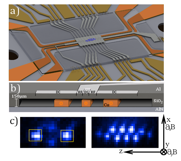
We use 40Ca+ confined in a planar Paul trap, which features trapping electrodes consisting of a nm thin layer of aluminum evaporated on a fused silica (SiO2) trap chip, see Fig. 1(a). We employ a five-wire design Chiaverini et al. (2005) with asymmetric rf electrodes. The width of the electrodes as seen in FIG. 1 b) is 700, 120, 100, 100, 700 m, respectively. This results in a trapping height of m above the aluminum surface House (2008). Segmented outer dc electrodes have a lenght of 430 m along the trap z-axis direction. The ponderomotive potential is generated in the plane by a drive frequency of MHz. Crystals with up to 10 ions, see Fig. 1(c) have been trapped using an rf peak-to-peak amplitude of 100 V resulting in a trap depth of about 35 meV. Typical secular trap frequencies are MHz, with the lowest frequency corresponding to the trap z-axis. The trap features a m deep cut-out on the backside to allow for the current carrying Cu-wires to be arranged as close to the ions as possible. Wires pointing parallel to the trap z-axis underneath the trap chip surface are etched from a m thick copper layer placed on a AlN chip carrier; the wire center to trapped ion distance is close 285m, see Fig. 1(b)
Zeeman sublevels of the 40Ca+ S1/2 ground state, =+1/2 and =-1/2 in a magnetic field of T perpendicular to the trap surface generated by external coils, split up in frequency by MHz. To drive the spin flip transition, we apply an rf current to the central current wire. The magnetic field gradient is generated by all three current wires: a magnetic quadrupole field forms at the position of the ions by applying static currents of +5.8, -4.8, +8.3 A, respectively. The asymmetric setting of currents i required for aligning the magnetic quadrupole to the trap potential, and we achieve a gradient of T/m at the ions position. We characterized the gradient by displacing the ion in radial direction from the trap center and measuring its Zeeman splitting Warring et al. (2013).
An experimental sequence starts with (i) Doppler cooling, (ii) optical pumping, optionally (iii) coherent excitation of the motional state. For this initialization of the ion crystal Poschinger et al. (2009), we use the 4S1/2 to 4P1/2 transition for Doppler cooling resulting in a mean phonon number of 20. Because of the constraint on the magnetic field direction we have chosen a frequency-selective optical pumping scheme yielding 0.98(2) fidelity of . Next, we continue with a (iv) sequence of radiofrequency pulses for spectroscopy or coherent manipulation. Note that the ions in a linear crystal experience the same magnetic field and radial magnetic field gradient. For individually addressing single ion spins in a linear crystal Piltz et al. (2014) we may tilt a crystal with respect to the trap axis, following a procedure we developed recently in a multi-layer Paul trap Kaufmann et al. (2017) or use a planar ion crystal which extends in radial direction. As a result, ions experience different magnetic field strengths and undergo different excitation. The readout of ions relies on (v) shelving followed by a (vi) fluorescence detection. For this, we transfer the population of the level to the metastable 3D5/2 =-3/2 and =+1/2 using a rapid adiabatic passage pulse Wunderlich et al. (2007). The fluorescence emitted upon resonant excitation of the 4S1/2 to 4P1/2 transition is detected on an EMCCD camera, and recorded in a single or multiple regions of interest (ROIs) that are set to selectively detect individual ions in the crystal, see inset of Fig. 1(a). After a number of repetions r we determine the probability .
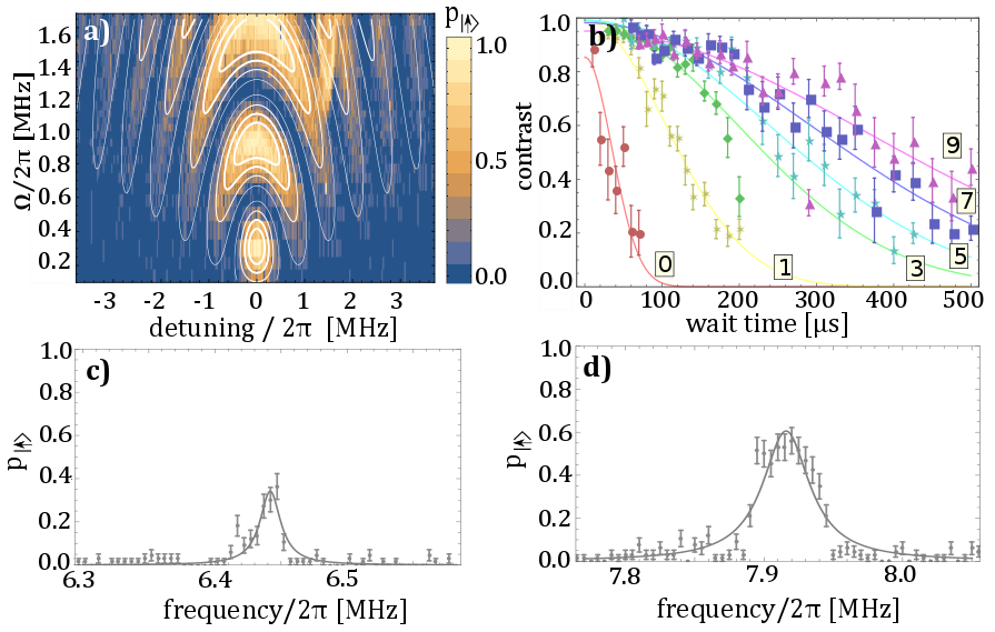
We characterize the radiofrequency excitation strength and the coherence with a single ion. Fig. 2 shows carrier and the red/blue motional sideband excitation. Under typical experimental conditions we drive the carrier transition with a Rabi frequency of . To optimize the excitation strenght of the motional sideband, we employ the trap control voltages and align the direction of the lower frequency radial mode (x) along the magnetic field gradient direction. The second radial mode (y), oriented almost perpendicular, can be tuned to show a 20 times weaker coupling. To determine an upper bound for the component of the magnetic field gradient pointing along the trap axis we employ a two ion crystal and vary the inter-ion distance between 5.6(4) and 12.1(3) m. We measure the dependence of the qubit frequency on the ion distance and infer a magnetic field gradient less than 0.02 T/m, resulting in a negligible axial sideband excitation with .
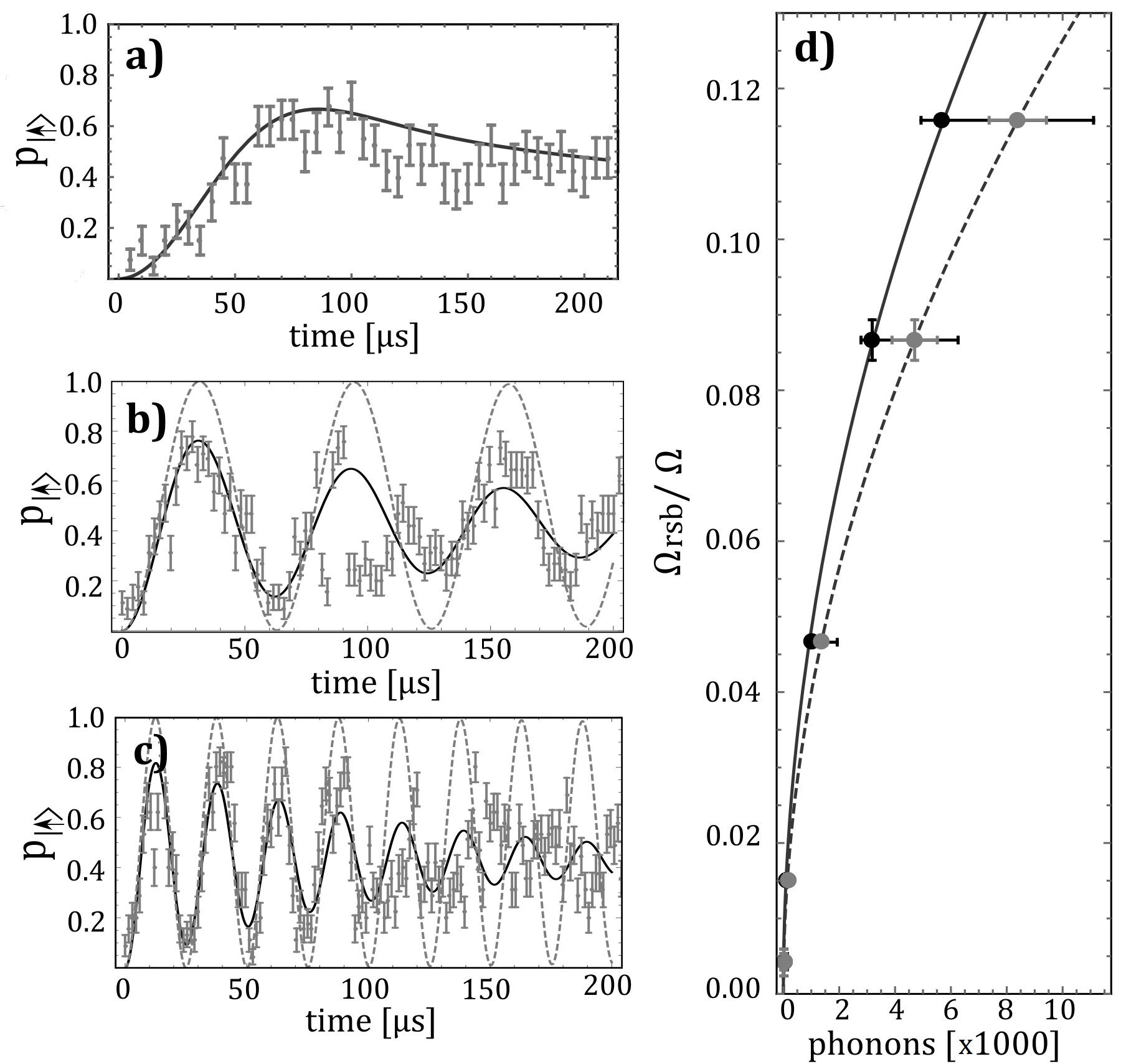
The first red sideband Rabi frequency depends on the phonon number in the mode as Wineland and Itano (1979) where denote associated Laguerre polynomials. For a magnetic field gradient of 16.3(9) T/m and a mode frequency of MHz we calculate an effective Lamb-Dicke factor of . Rabi oscillations result from the summation with the phonon number distribution as . For an ion in a thermal state after Doppler cooling the dynamics of the red sideband is shown in Fig. 3(d). To increase the effective Rabi frequency we inject an alternating resonant electric field to excite the radial mode coherently. Then we drive Rabi oscillations for different power levels of electric excitation, see Fig. 3(b, c), and obtain the mean phonon number of the coherent distribution, with = 8400(1000) and 1360(180), respectively. A fast red sideband transition was achieved in s. To cross-check the results of , we drive Rabi oscillations on the optical SD5/2 transition, and its variation with the same injected electric fields and obtain and , respectively, see Fig. 3(d) Alonso et al. (2016). This way, we extract from the fit, which agrees within errors with the calculated value.
To measure the coherence time we use a single ion, apply a /2 carrier pulse, followed by a wait time, and a second /2 pulse. Ramsey fringes are recorded, when scanning the phase of the second pulse. The fringe contrast is fitted by a Gaussian decay with a /e-time of s, see Fig. 2(b). For an odd number l of spin-echo refocussing pulses, we find that the measured coherence time scales with l0.64(13) and for l we reach ms. Such power law indicates a Lorentzian noise spectrum Bar-Gill et al. (2013) which in our case is fully dominated by fluctuations of currents mA to generate the magnetic field gradient. Trap control voltages are sufficiently stable such that the ion crystal is kept aligned within the gradient field within a small fraction of the radial wave packet size of 39(3) nm.
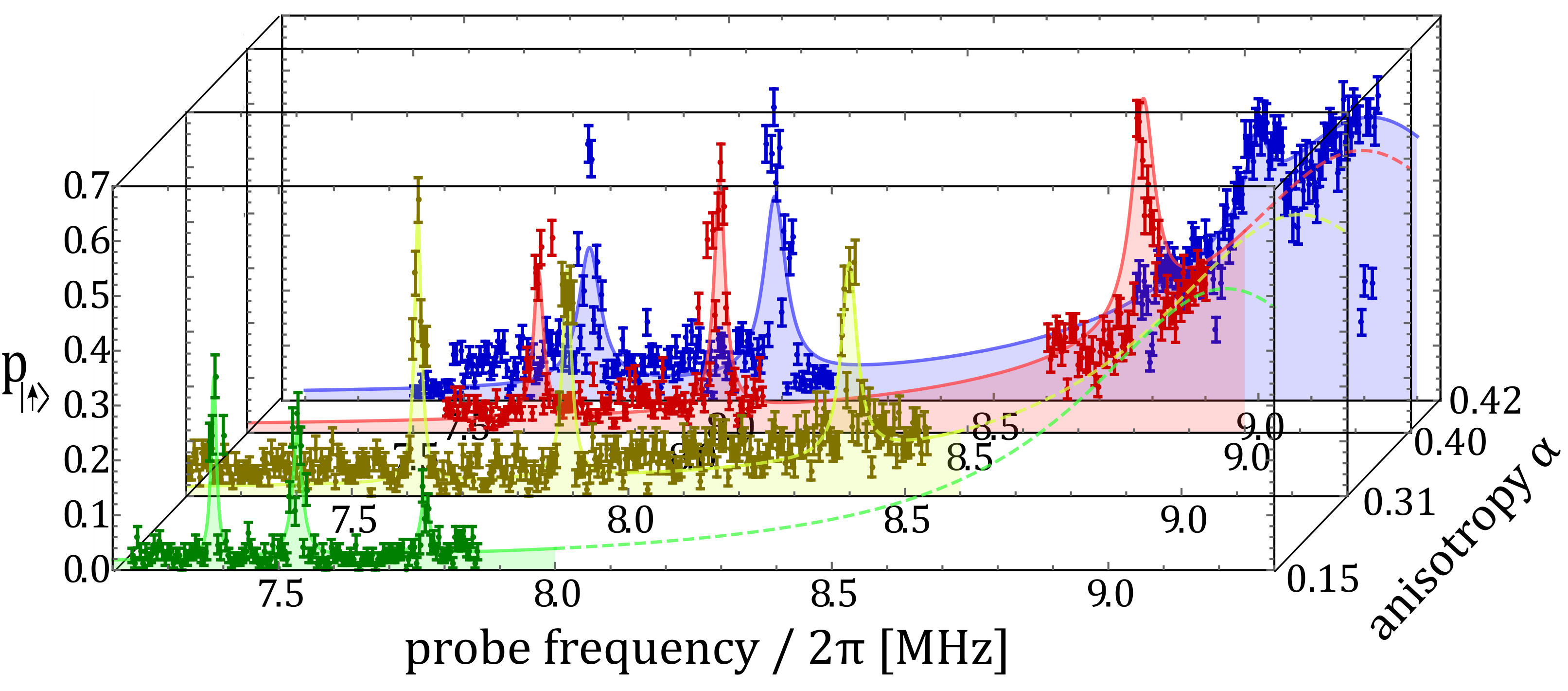
We investigate spin transitions in the vicinity of a structural transition of a small ion crystal by adjusting the anisotropy parameter to generate the desired configurations. For small anisotropy ions arrange in linear configuration along the trap axis. For above the critical value ions are forming a zigzag or planar crystal Birkl et al. (1992); Fishman et al. (2008); Kaufmann et al. (2012). In case of a three-ion crystal we drive the spectroscopy sequence (i) to (v) recording fluorescence only on one of the outer ions, see Fig. 4. All three modes with the eigenvectors (1,1,1)/, (1,0,-1)/ and (1,-2,1)/ containing radial x-direction appear. Increasing the value of towards , here 0.416(1), eigenfrequencies become smaller such that the observed resonances approach the carrier and getting more pronounced as their effective Lamb-Dicke factors are increasing. The spectrum for = 0.42 is taken already beyond the critical point with a zigzag crystal extending in the radial direction by about 1.2 m. The lowest sideband mode near a drive frequency of MHz corresponds to a zigzag vibration of the crystal, with an eigenfrequency of kHz, consistent with the calculated value of kHz.
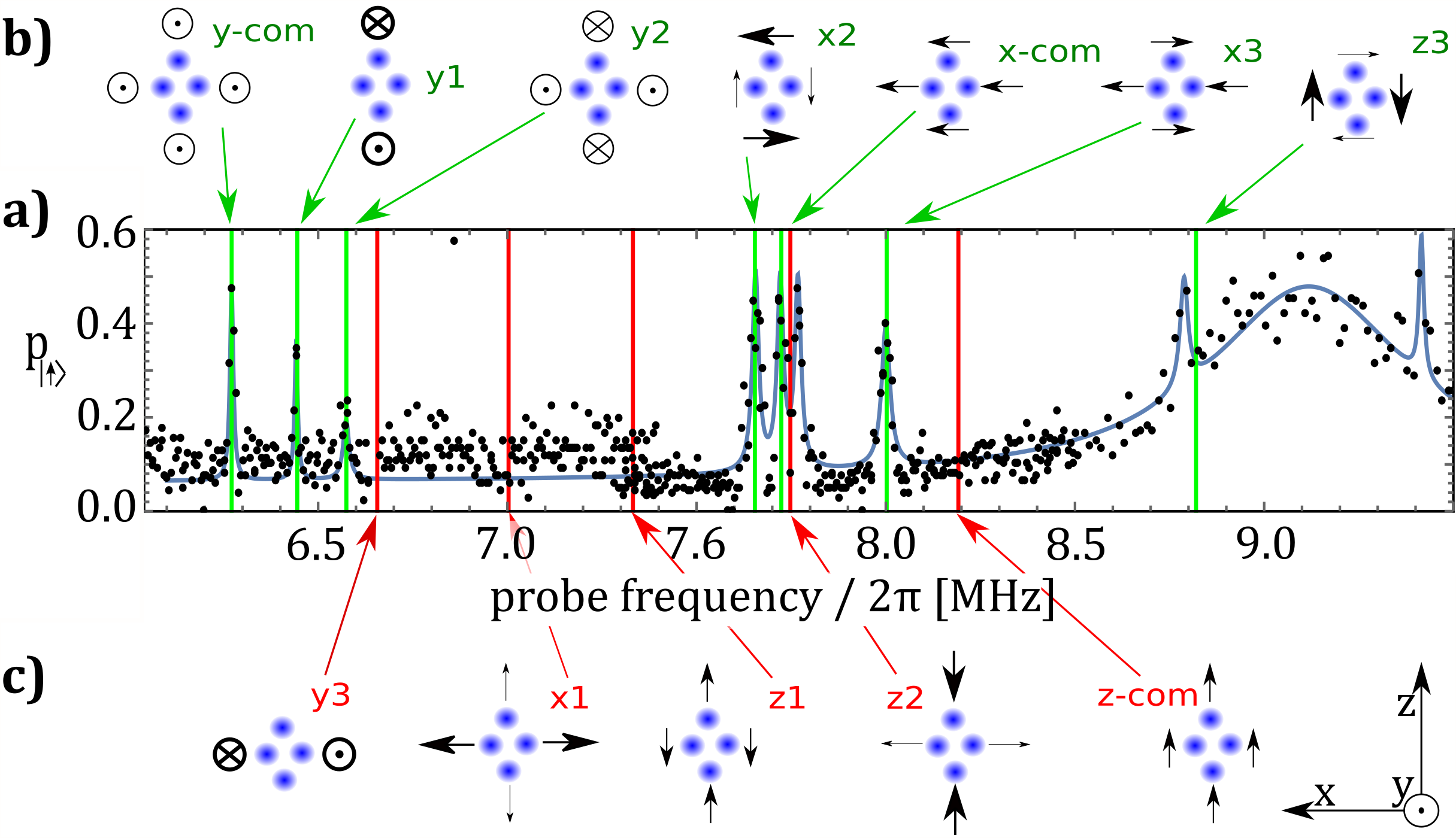
We turn now to the basic case of a planar crystal with four ions, see Fig. 1(c). We initialize the two ions which are placed on the rf node of the trap. After an rf pulse of 5 ms their spin state is measured using fluorescence detection (within ROIs). Applying the spectroscopic sequence we investigate the 43 eigenmodes of common vibration. The magnetic field gradient couples only vibrational modes to the rf transition, which feature ion oscillations in the radial direction, i.e. parallel to the gradient, cf. Fig. 5. The radial x-modes, which are aligned with the gradient, show up as resonances x-com, x and x (green), while the eigenvectors of x do not point along the magnetic field gradient and are therefore not excited, resonance frequencies indicated in red. As the rf excitation was at high power, saturating the transition with kHz we also observe the radial modes with weaker projection y-com, y, and y (green), while for y only ions move which are not in ROIs (red). The axial z-modes do not appear, except z, which is in close spectral vicinity to the x-com mode. Here, we assume that the strong rf drive field induces a mixing process between x-com and z, resulting in dressed modes which show up in the spectrum. As ions are not all located on the radiofrequency node of the trap they undergo micromotion, a precise calculation of eigenfrequencies would require a Floquet-Lyapunov Kaufmann et al. (2012). Because of a sufficiently small Matthieu parameter even a pseudo-potential calculation fits the observed resonances well.
We have shown coupled dynamics of motional and internal spin states with a transition frequency as low as MHz by employing static magnetic field gradients created with current-carrying wires placed underneath an ion trap chip. We presented detailed resolved-sideband spectoscopy in linear and planar multi-ion crystals. Knowledge of the eigenmodes and frequencies are paramount for the implementation of quantum simulation and tailoring of interaction strengths between spins.
In future experiments we plan to significantly improve coherence time and magnetic field gradient (up to 150 T/m) which can be achieved by using a much more advanced current suppy scheme or by permanet magnets placed underneath the trap chip. Slow decoherence may be corrected for by advanced refocusing schemes Piltz et al. (2013). Recently fast and robust gate operations have been proposed Arrazola et al. (2017) and would be in experimental reach. Another interesting direction are studies of phase transitions with competing spin-spin interactions Kim et al. (2010) implemented on larger planar ion crystals or studies of revealing nonlinear mode couplings Gessner et al. (2014); Lemmer et al. (2015)
We acknowledge A. Bautista-Salvador and N. Daniilidis for help with the trap fabrication. We thank U. Poschinger and B. Lekitsch for helpful comments and careful reading. We acknowledge financial support by the DFG through the DIP program Grant No. SCHM 1049/7-1, the SFB/TR-49 and within the EU-STREP EQuaM.
References
- Häffner et al. (2008) H. Häffner, C. Roos, and R. Blatt, Physics Reports 469, 155 (2008).
- Monz et al. (2011) T. Monz, P. Schindler, J. T. Barreiro, M. Chwalla, D. Nigg, W. A. Coish, M. Harlander, W. Hänsel, M. Hennrich, and R. Blatt, Phys. Rev. Lett. 106, 130506 (2011).
- Gaebler et al. (2016) J. Gaebler, T. Tan, Y. Lin, Y. Wan, R. Bowler, A. Keith, S. Glancy, K. Coakley, E. Knill, D. Leibfried, and D. Wineland, Phys. Rev. Lett. 117, 060505 (2016).
- Mintert and Wunderlich (2001) F. Mintert and C. Wunderlich, Phys. Rev. Lett. 87, 257904 (2001).
- Chiaverini and Lybarger Jr. (2008) J. Chiaverini and W. E. Lybarger Jr., Phys. Rev. A 77, 022324 (2008).
- Weidt et al. (2016) S. Weidt, J. Randall, S. C. Webster, K. Lake, A. E. Webb, I. Cohen, T. Navickas, B. Lekitsch, A. Retzker, and W. K. Hensinger, Phys. Rev. Lett. 117, 220501 (2016).
- Ospelkaus et al. (2011) C. Ospelkaus, U. Warring, Y. Colombe, K. Brown, J. Amini, L. D., and D. Wineland, Nature 476, 181 (2011).
- Harty et al. (2016) M. Harty, T. P.and Sepion, D. T. C. Allcock, C. J. Ballance, J. Tarlton, and D. M. Lucas, Phys. Rev. Lett. 117, 140501 (2016).
- Khromova et al. (2012) A. Khromova, C. Piltz, B. Scharfenberger, T. F. Gloger, M. Johanning, A. F. Varón, and C. Wunderlich, Phys. Rev. Lett. 108, 220502 (2012).
- Lake et al. (2015) K. Lake, S. Weidt, J. Randall, E. D. Standing, S. C. Webster, and W. K. Hensinger, Phys. Rev. A 91, 012319 (2015).
- Kawai et al. (2017) Y. Kawai, K. Shimizu, A. Noguchi, S. Urabe, and U. Tanaka, J. Phys. B 50, 025501 (2017).
- Kunert et al. (2014) P. J. Kunert, D. Georgen, L. Bogunia, M. T. Baig, M. A. Baggash, M. Johanning, and C. Wunderlich, Appl. Phys. B 114, 27 (2014).
- Porras et al. (2008) D. Porras, F. Marquardt, J. von Delft, and J. I. Cirac, Phys. Rev. A 78, 010101 (2008).
- Wall et al. (2017) M. L. Wall, A. Safavi-Naini, and A. M. Rey, Phys. Rev. A 95, 013602 (2017).
- Kim et al. (2010) K. Kim, M. Chang, S. Korenblit, R. Islam, E. Edwards, J. Freericks, G. Lin, L. Duan, and C. Monroe, Nature 465, 590 (2010).
- Lanyon et al. (2011) B. P. Lanyon, C. Hempel, D. Nigg, M. Müller, R. Gerritsma, F. Zähringer, P. Schindler, J. T. Barreiro, M. Rambach, G. Kirchmair, M. Hennrich, P. Zoller, R. Blatt, and C. F. Roos, Science 334, 57 (2011).
- Jurcevic et al. (2014) P. Jurcevic, B. P. Lanyon, P. Hauke, C. Hempel, P. Zoller, R. Blatt, and C. F. Roos, Nature 511, 202 (2014), letter.
- Islam et al. (2013) R. Islam, C. Senko, W. C. Campbell, S. Korenblit, J. Smith, A. Lee, E. E. Edwards, C.-C. J. Wang, J. K. Freericks, and C. Monroe, Science 340, 583 (2013).
- Gessner et al. (2014) M. Gessner, F. Schlawin, H. Häffner, S. Mukamel, and A. Buchleitner, New J. Phys. 16, 092001 (2014).
- Lemmer et al. (2015) A. Lemmer, C. Cormick, C. Schmiegelow, F. Schmidt-Kaler, and M. Plenio, Phys. Rev. Lett. 114, 073001 (2015).
- Johanning et al. (2009) M. Johanning, A. Varón, and C. Wunderlich, Journal of Physics B: At. Mol. Opt. Phys. 42, 154009 (2009).
- Zhang et al. (2017) J. Zhang, G. Pagano, P. Hess, A. Kyprianidis, P. Becker, H. Kaplan, A. Gorshkov, Z. Gong, and C. Monroe, Nature 551, 601 (2017).
- Jurcevic et al. (2017) P. Jurcevic, H. Shen, P. Hauke, C. Maier, T. Brydges, C. Hempel, B. Lanyon, M. Heyl, R. Blatt, and C. Roos, Phys. Rev. Lett. 119, 080501 (2017).
- Britton et al. (2012) J. Britton, B. Sawyer, A. Keith, C. Wang, J. Freericks, H. Uys, M. Biercuk, and J. Bollinger, Nature 484, 489 (2012).
- Bermudez et al. (2011) A. Bermudez, J. Almeida, F. Schmidt-Kaler, A. Retzker, and M. Plenio, Phys. Rev. Lett. 107, 207209 (2011).
- Mielenz et al. (2016) M. Mielenz, H. Kalis, M. Wittemer, F. Hakelberg, R. Schmied, M. Blain, P. Maunz, D. Moehring, D. Leibfried, U. Warring, and T. Schaetz, Nat. Commun. 7, 11839 (2016).
- Kumph et al. (2016) M. Kumph, P. Holz, K. Langer, M. Meraner, M. Niedermayr, M. Brownnutt, and R. Blatt, New J. Phys. 18, 023047 (2016).
- Kotler et al. (2014) S. Kotler, N. Akerman, N. Navon, Y. Glickman, and R. Ozeri, Nature 510, 376 (2014).
- Wunderlich (2002) C. Wunderlich, “Conditional spin resonance with trapped ions,” in Laser Physics at the Limits, edited by H. Figger, C. Zimmermann, and D. Meschede (Springer, Berlin, Heidelberg, 2002) p. 261.
- Chiaverini et al. (2005) J. Chiaverini, R. Blakestad, J. Britton, J. Jost, C. Langer, D. Leibfried, R. Ozeri, and D. Wineland, Quant. Inf. Comput. 5, 419 (2005).
- House (2008) M. G. House, Phys. Rev. A 78, 033402 (2008).
- Warring et al. (2013) U. Warring, C. Ospelkaus, Y. Colombe, K. Brown, J. Amini, M. Carsjens, D. Leibfried, and D. Wineland, Phys. Rev. A 87, 013437 (2013).
- Alheit et al. (1996) R. Alheit, S. Kleineidam, F. Vedel, M. Vedel, and G. Werth, Int. J. Mass Spectrom. Ion Processes 154, 155 (1996).
- Poschinger et al. (2009) U. Poschinger, G. Huber, F. Ziesel, M. Deiß, M. Hettrich, S. Schulz, K. Singer, G. Poulsen, M. Drewsen, R. Hendricks, and F. Schmidt-Kaler, J. Phys. B 42, 154013 (2009).
- Piltz et al. (2014) C. Piltz, T. Sriarunothai, A. Varón, and C. Wunderlich, Nat. Comm. 5, 4679 (2014).
- Kaufmann et al. (2017) H. Kaufmann, T. Ruster, C. Schmiegelow, M. Luda, V. Kaushal, J. Schulz, D. von Lindenfels, F. Schmidt-Kaler, and U. Poschinger, Phys. Rev. A 95, 052319 (2017).
- Wunderlich et al. (2007) C. Wunderlich, T. Hannemann, T. Körber, H. Häffner, C. Roos, W. Hänsel, R. Blatt, and F. Schmidt-Kaler, J. Mod. Opt. 54, 1541 (2007).
- Wineland and Itano (1979) D. J. Wineland and W. M. Itano, Phys. Rev. A 20, 1521 (1979).
- Alonso et al. (2016) J. Alonso, F. Leupold, Z. Solèr, M. Fadel, M. Marinelli, B. Keitch, V. Negnevitsky, and J. Home, Nature Commun. 7, 11243 (2016).
- Bar-Gill et al. (2013) N. Bar-Gill, A. Pham, L. amd Jarmola, D. Budker, and R. Walsworth, Nat. Phys. 4, 1743 (2013).
- Birkl et al. (1992) G. Birkl, S. Kassner, and W. H., Nature 357, 310 (1992).
- Fishman et al. (2008) S. Fishman, G. De Chiara, T. Calarco, and G. Morigi, Phys. Rev. B 77, 064111 (2008).
- Kaufmann et al. (2012) H. Kaufmann, S. Ulm, G. Jacob, U. Poschinger, H. Landa, M. Retzker, A. amd Plenio, and F. Schmidt-Kaler, Phys. Rev. Lett. 109, 263003 (2012).
- Piltz et al. (2013) C. Piltz, B. Scharfenberger, A. Khromova, A. F. Varón, and C. Wunderlich, Phys. Rev. Lett. 110, 200501 (2013).
- Arrazola et al. (2017) I. Arrazola, J. Casanova, J. Pedernales, Z. Wang, E. Solano, and M. Plenio, arXiv:1706.02877 (2017).