Lifted graphene nanoribbons on gold: from atomic smooth sliding to multiple stick-slip regimes
Abstract
Graphene nanoribbons (GNRs) physisorbed on a Au(111) surface can be picked up, lifted at one end, and made slide by means of the tip of an atomic-force microscope. The dynamical transition from smooth sliding to multiple stick-slip regimes, the pushing/pulling force asymmetry, the presence of pinning, and its origin are real frictional processes in a nutshell, in need of a theoretical description. To this purpose, we conduct classical simulations of frictional manipulations for GNRs up to nm in length, one end of which is pushed or pulled horizontally while held at different heights above the Au surface. The emergence of stick-slip originating from the short 1D edges rather than the 2D “bulk”, the role of adhesion, of lifting, and of graphene bending elasticity in determining the GNR sliding friction are clarified theoretically. The understanding obtained in this simple context is of additional value for more general cases.
Keywords: graphene, nanoribbon, stick-slip, friction.
1 Introduction
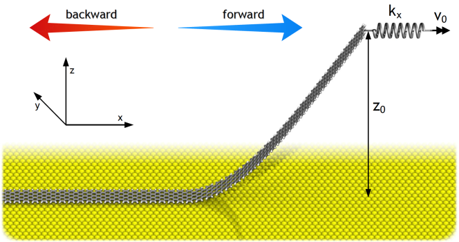
Nanofriction, a property of moving nanometer-sized interfaces widely investigated experimentally by atomic force microscopy (AFM), is progressively unveiling the detailed mechanisms which affect the mechanical energy dissipation in well-controlled frictional setups [1, 2, 3, 4, 5]. Graphene is an important actor in this quest, because its strong resilient structure makes it possible to push and slide flakes and planes once deposited on suitable well-defined surfaces [6]. Graphene nanoribbons (GNRs) too can be created and physisorbed on Au(111) surfaces, by means of clever in-situ molecular-assembly techniques [7, 8]. Once there, they can be picked up at one extreme and forced to slide by a moving tip [9]. The dynamics of the GNR once dragged forward and backward (calling forward the pulling, backward the pushing, as sketched in Fig. 1) may show distinct regimes of motion depending on the lifting height, . At small lifting heights ( nm) there is an almost symmetric behavior between forward and backward scans, not unlike that observed experimentally for the low-lifted GNR [9]. At larger heights ( nm), different stick-slip patterns and periodicities emerge with a substantial asymmetry between the two.
The present theoretical study aims at understanding the main features of frictional dissipation in these systems.
Anticipating our final conclusions, the forward-backward symmetric frictional response at small lifting heights stems from the limited extent of elastic deformations accumulated by the GNR when pulled against an energy barrier. At increasing lifting height, the bending energy required to deform the GNR decreases and the mechanical response under driving becomes different for the two opposite scan directions; reaching the minimum energy needed to initiate sliding (the Peierls-Nabarro barrier [10]), the GNR dynamics starts to develop asymmetric features in the emerging stick-slip regime for forward and backward pulling. The main effects of this enhanced elastic deformation are an increased period of the stick-slip motion and the occurrence of a possible “peeling” effect in the backward trace for increasing lifting height.
In addition, we show that the peaks of the time-resolved frictional force traces depend critically on the effective contact length of the GNR section still adhering to the substrate. The force peak amplitudes exhibit an oscillation versus effective length of the GNR mostly due to the imperfect compensation of the moiré superstructure at the two ends of the physisorbed part of the GNR. This effect is also related to the oscillatory behavior of the static friction force versus size reported in the past for totally adhering GNRs [11].
2 System and method
We simulate an armchair GNR, consisting of a stripe of alternating triplets and pairs of carbon hexagons, of width nm and length nm. This length, a factor larger than that of our reference experiment [9], enables us at the same time to reproduce qualitatively the behavior of the force traces at small lifting height obtained experimentally with a much shorter GNR, and to anticipate phenomena that should come into play when the lifting height is sufficiently large ( nm), a regime where GNRs will undergo important elastic deformations. All the edge C-atoms at the periphery of the GNR are passivated with hydrogens, in order to faithfully reproduce the experimental conditions [9], and to obtain realistic peripheral C-C bond lengths, which are sensitive to saturation effects.
The simulated GNR is deposited on an unreconstructed Au(111) surface along the R30 direction, i.e. the GNR long axis lies parallel to the Au crystallographic direction [11]. The atomistic dynamics of the GNR is simulated using the LAMMPS package [12] by means of a REBO force field [13] for C-C and C-H interaction, plus 2-body C-Au and H-Au interactions of the (6-12) Lennard-Jones (LJ) type, as parametrized in Ref. [11]. In the following we refer to these energy contributions as and , respectively.
Starting from a fully relaxed GNR configuration, we lift progressively one end row (three C atoms) of the GNR through a fictitious ultra-hard spring ( N/m), producing unilateral detachment up to a desired height nm (with respect to the unlifted GNR configuration), followed by a further relaxation in the lifted geometry. After that, the mean coordinate of the lifted end of the GNR, while held all the time at its fixed height , is connected to a soft horizontal pulling spring ( N/m) and dragged forward or backward with constant velocity m/s. This procedure aims at mimicking, at least qualitatively, the lateral manipulation of a GNR, as done in AFM experiments [9]. While the real-time evolution of the underlying Au substrate is not explicitly simulated, the GNR C and H atoms obey a dissipative Langevin dynamics, at zero temperature and damping parameter ps-1, which prevents the externally-driven nanoribbon from heating up.
The specific adopted value ensures, we checked, a realistic relative balance of inertial and dissipative terms, as discussed later, and does not significantly affect the qualitative outcome of the simulated tribological response within a quite broad range of values.
The equation of motion for each of the three C atoms of the lifted edge reads:
| (1) |
where are the positions of the three C-atoms of the lifted edge, and the unit vectors directed along the - and -axis, and is the total potential energy including the interaction among all GNR particles and between particles and substrate. The equation of motion for all the other atoms with coordinates is
| (2) |
3 Results and discussion
We extract the instantaneous simulated frictional force as the elastic force that the soft pulling spring exerts on the GNR
| (3) |
where is the mean -coordinate of the lifted end of the GNR, obtained by averaging the coordinates of the three lifted-edge C atoms.
For each given lifting height , the simulated AFM force trace is a plot of as a function of time, or equivalently of the displacement of the fixed-speed end of the spring . For ease of comparison, we express this displacement in units of the lattice spacing of the gold substrate in the pulling direction, Å.
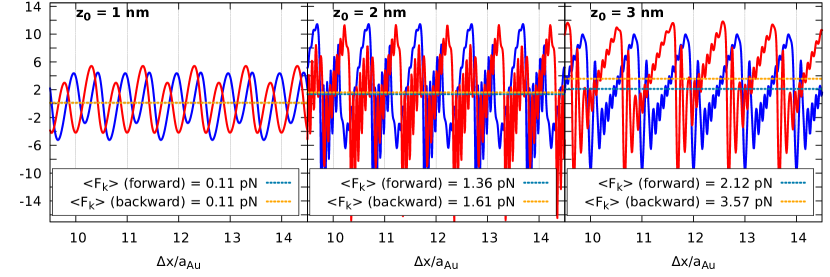
Discarding initial transients, Figures 2 and 3 show the steady-state simulated frictional forces for lifting heights nm, and nm, respectively. We note that, for a direct comparison highlighting intrinsically different features between the forward (blue solid curves) and backward (red dashed curves) traces we show the latter forces reversed in sign and plotted versus positive displacements, thus not displaying the typical dissipation frictional loop obtained for standard AFM back-and-forth scans. At low lifting heights, nm, Fig. 2, the computed force traces for the forward and backward scans exhibit a symmetric response, as observed in experiment [9]. Note that the experimental traces also contain a long-wavelength modulation [9] due to the Au-substrate reconstruction, here neglected. At the small lifting of nm the sliding force oscillation reflecting the atomic corrugation on Au(111) is smooth in both directions (see Movies in Supplementary data). As a result, the average frictional force ( pN) is close to zero, confirming the superlubric characteristic of the interface. We note that, due to the lattice mismatch between the GNR structure and the underneath substrate along the considered R30 direction, there exist two inequivalent good matching interface configurations, shifted almost by one half of the Au lattice spacing, giving rise approximately to a period doubling in the force traces.
The frictional evolution for increasing lifting height is remarkable. A first change in the dynamical response appears between and nm lifting. At nm the smooth sliding is replaced by atomic stick-slip with the same periodicity of the smooth oscillations at nm. With the occurrence of this intermittent dynamics, usually marking in tribological systems the demise of superlubricity [2], we very reasonably find that friction rises by an order of magnitude. It can be noted that at the end of each slip the instantaneous force oscillates considerably, in both forward and backward traces, due to inertial overshooting. At higher lifting height a similar atomic stick slip is again observed, but without the delicate superimposed period duplication observed at smaller .
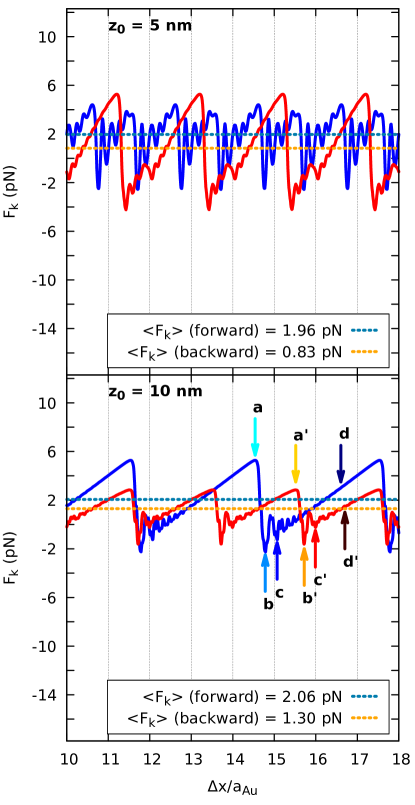
A different scenario emerges for higher lifting, such as and nm, Fig. 3. Forward and backward traces are not symmetric anymore, and multiple jumps [14] start to show up (see Movies in Supplementary data), contrasting the basically single stick-slip regime observed at small lifting. The slip distance depends quite generally on the lifting height, which controls the mechanical softness of the lifted part, and on the pulling direction. For instance, at nm the forward force trace is single slip, while that of the corresponding backward scan becomes double. Conversely, at nm the forward trace shows a stick-slip period of three lattice spacings, as opposed to two lattice spacings in the backward case.
Such asymmetric response, as we shall see, is determined by the interplay of two main effects. Firstly, forward and backward configurations imply different effective contact areas between the GNR and the substrate. Since the static friction oscillates widely with GNR contact length [11], small differences in the effective contact length can lead in general to quite different static-friction thresholds. As a result, small differences in may lead to different dynamical friction patterns.
Secondly, as detailed in Sect. 4 below, the interplay between bending energy and adhesion differs strongly in the two pulling directions.
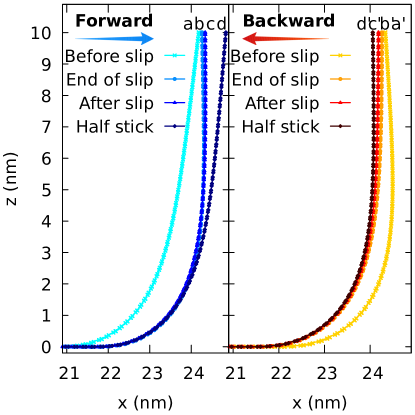
A first insight in the different forward and backward GNR dynamics can be obtained by examining the characteristic shape of the GNR at specific instants during the stick-slip motion. Figure 4 shows the lateral profile of the GNR in the forward and backward motion at nm, at four distinct instants marked by arrows in Fig. 3. The main features of the stick-slip dynamics in the forward and backward motion are very similar: once the spring reaches the critical elongation to overcome the Peierls-Nabarro barrier (a/a’), a slip event occurs, the physisorbed section sprints forward/backwards and reaches a new pinned position (b/b’), with a new increase (in the forward motion) /decrease (in the backward motion) of the GNR bending energy, which is then progressively released/absorbed during the subsequent stick phase (cd / c’d’).
4 Energy considerations
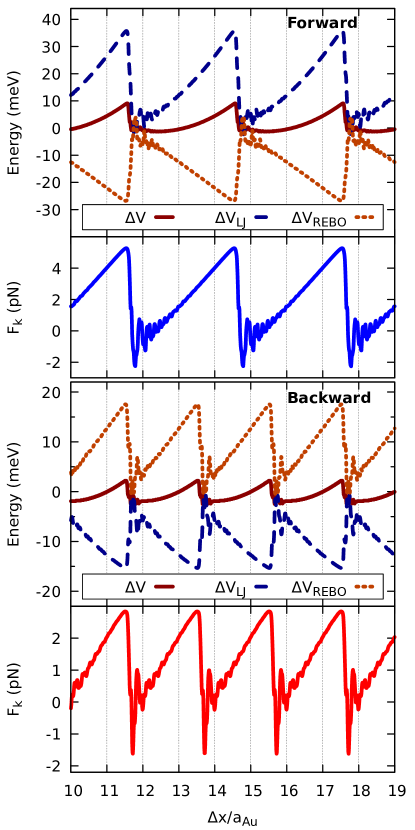
It is instructive to analyse how the individual energy contributions coming from the elastic bending of the GNR and from the adhesion to the substrate evolve during the stick-slip frictional dynamics. Consider for instance the motion of the GNR at large nm. The total GNR potential energy is the sum of an intra-ribbon term, from the C-C and C-H bonds, which controls the planar and bending stiffness, plus a second term, , stemming from the C-Au and H-Au interactions which controls the adhesion of the unlifted part of the GNR. The time variation of with respect to our reference configuration at , (a relaxed GNR with one lifted end), can be written as
| (4) |
For forward and backward motion, Fig. 5 compares the frictional force evolution (already displayed in Fig. 3) and that of the potential energy terms , and . Note the opposite contributions to the total GNR energy for forward and backward sliding. In the forward scan, the intra-ribbon contribution is negative, with an energy gain due to the decrease of GNR curvature in the detached part, as discussed in Sect. 3 above. At the same time, the system loses adhesive energy, not just because the external force works to overcome the static friction energy barrier which blocks the sliding, but mainly because the physisorbed section shortens in length as the GNR end is pulled forward (see also the zoomed-in GNR -profile in Fig. 6), causing an increase of . Exactly the opposite occurs for backward sliding, where is positive, owing to the curvature increase of the detached part, whereas is negative reflecting a corresponding improvement of adhesion due to an increased contact length (see again Fig. 6). For completeness, we note that, at even larger values, the backward-driven GNR may initiate to peel off the Au surface during the stick phase, thus starting decreasing the adhesive contribution.
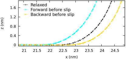
There is a clear correspondence between the general energy evolution described above and the lifted nanoribbon geometry. Figure 6 compares the shape profile of the GNR near the detachment point, just before the slip either forward or backward. By comparison with the relaxed, static shape (zero force), the curvature and the physisorbed section of the GNR are respectively smaller in the forward case, and larger in the backward case.
5 Role of the ribbon short edge and uncompensated moiré pattern
As was observed in our previous study of the fully adhering – non-lifted – GNRs [11], the 2D “bulk” of the GNR/Au(111) interface is incommensurate and structurally lubric (“superlubric”). Like in other superlubric systems, the static friction – the minimal force required to set the interface into sliding motion – does not grow (on average) as much as the contact area. Specifically, for a non-lifted GNR, the static friction oscillates around a fairly constant mean value as a function of the nanoribbon length [11]. This indicates that the edges, here the short ones, are mostly responsible for pinning – a feature similarly found in incommensurate rare-gas islands deposited on metal surfaces [15] and in twisted bilayer graphene [16]. The strong oscillation of the static friction around the constant average trend as a function of the GNR length is related to the “uncompensated” moiré pattern near the GNR ends, i.e. the residual of divided by the moiré-pattern wavelength. This friction oscillation may involve variations in comparable with the average [16]. This appears to be the case also with lifted GNRs, where the effective contact length , defined below, varies as a function of and changes dynamically in time.
By lifting the GNR at successively increasing heights, the effective contact length will change, giving rise to minima/maxima of the static friction force. We define the effective contact length of a lifted GNR by dividing by the same quantity per unit length of an infinite-length simulated GNR with periodic boundary conditions, :
| (5) |
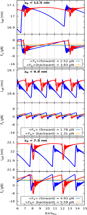
where is the total interaction energy between the GNR and the substrate at the lifting height and at time . It turns out that for lifting heights between nm and nm we cover one complete period of the static friction [11]. Figure 7 shows the force traces corresponding to lifting heights , , and nm, the first and the last ones corresponding to expected local maxima of the oscillating static friction versus effective size, the second to a local minimum, along with the corresponding change in time of the effective contact length of Eq. (5). As expected, the peaks in and the mean friction forces are larger at lifting heights that correspond to the expected local maxima of static friction, namely nm and nm, than at the expected local minimum, namely nm.
For a grid of lifting heights , Fig. 8 reports the maximum force obtained from the peaks just before slip once a steady stick-slip regime is established versus the effective contact length for that height. The best fitting sinusoids of the form
| (6) |
for both the forward and backward motion, are also drawn as reference. , , , are fitting parameters. The values and the nm period oscillation of the lifting-dependent maximum force compares reasonably well with the established static friction trend as a function of the non-lifted GNR length [11]. Somewhat larger in magnitude, both forward and backward maximum forces share the same oscillation as the static friction of the non-lifted GNR with length equal to the effective lifted GNR length . This result further confirms that the uncompensated, edge-related, part of the moiré pattern determines the magnitude of the maximum kinetic-friction force before slip.
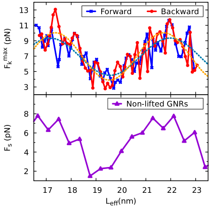
Figure 8 compares the maximum kinetic friction with the static friction obtained for fully adhering GNRs [11]. For a given system in the underdamped regime, the two quantities should match in the limit of vanishing driving velocity . At finite velocity it is generally expected that , with static friction always exceeding dynamic one. Here, naively, we observe the opposite. This might look counterintuitive, as one might expect a larger friction for fully adhering GNRs. However, as pointed out above, static friction is dominated by the two GNR short-ends in this superlubric system. The two short-edges are equivalent in the unlifted case, and are responsible for the frictional oscillations as a function of [11]. By contrast, in the case of lifted GNR the bending at the leading edge produces a termination which is strongly inequivalent to that of the trailing edge. As a result, cancellation of the lateral forces acting on the two ends is more problematic, yielding generally an overall larger friction.
It is also worth asking if GNRs might show any tendency to peel off the substrate when driven backward at large lifting heights. As seen in Figures 5 and 6, the backward stick-slip motion is accompanied by an increase of adhesion in the stick state, while a decrease of adhesion is seen in the forward motion. In Figure 7, nm, this fact is confirmed by the increase of in the stick state of the backward motion. In these cases no tendency to peel off is registered. In contrast, at a lifting height of nm, we notice that in the backward motion the adhesive length increases up to a maximum and then decreases again with a sort of parabolic trend. This indicates that the spring initially pushes the physisorbed atoms adjacent to the bent GNR section down in closer contact with substrate, promoting an increased adhesion. Once the extension of the driving spring is sufficiently large, the GNR starts to detach from the substrate, causing a loss of adhesion. This analysis shows that, depending on the lifting height and the precise value of the static friction barrier at that height, the GNR can indeed start to peel off from the substrate. In all simulated cases, as backward pulling continued, a slip event would release the bending stress before the peeling instability would fully develop and lead the GNR to a complete peel off. As a general rule, peeling is more pronounced for those combinations of and GNR length leading to those producing the largest possible static friction threshold, and generally for larger lifting height, because of the softer GNR elasticity and greater mechanical advantage.
6 Conclusions
We have investigated the dynamical friction of lifted graphene nanoribbons on a Au(111) substrate by means of non-equilibrium molecular-dynamics simulations. Mimicking the experimental setup of Kawai et al. [9] we reproduce and interpret the observed frictional regimes of the GNR as a function of the lifting height . For increasing , we predict a remarkable transition from smooth sliding to atomic stick-slip, characterized initially by single slips, and then by multiple slips at larger heights. Specifically, the periodicity of the stick-slip dynamics is dominated by the bending elasticity of the GNR, which enables larger slip distances at larger heights. The augmented softness, introduced by bending of the GNR as increases, plays opposite roles for the two driving directions, decreasing (forward) and increasing (backward) the GNR/substrate adhesion. The lifting-dependent amplitude of the instantaneous friction force is not a ”bulk” feature, and is entirely determined by the short edges of the GNR – in the lifted case as well as in the non-lifted case.
We find an oscillation of friction with lifting height. That in turn is related, via identification of an effective GNR contact length of the physisorbed GNR section, to the moiré-pattern lack of compensation close to the edges, qualitatively similar but quantitatively different to that occurring in the static friction of unlifted GNRs [11]. Past experiments on lifted GNR sliding [9] have not yet explored the new regime which we describe here, essentially due to the relatively small length of the GNR used there ( nm only), whereby the GNR lifted at nm was almost completely detached from the Au-substrate, very nearly peeled off. Our much longer – 30 nm – simulated GNR, only approaches peeling at lifting heights larger than nm, as shown by the time evolution of the effective contact length. Present predictions about the sliding should be borne out by future experiments, hopefully on longer GNRs, as well as on more general physisorbed flakes of graphene and other 2D materials.
In these systems, they should be able to find, for increasing lifting heigthts, a transition from smooth sliding to stick-slip, the asymmetric forward/backward friction, and a peel-off instability.
Acknowledgments
We acknowledge useful discussions with E. Meyer, E. Gnecco and A. Benassi. Work in Trieste was carried out under ERC Grant 320796 MODPHYSFRICT. The COST Action MP1303 is also gratefully acknowledged.
Acknowledgments
We acknowledge useful discussions with E. Meyer, E. Gnecco and A. Benassi. This work was supported by the ERC Advanced Grant No. 320796-MODPHYSFRICT. The COST Action MP1303 is also gratefully acknowledged.
References
- [1] Krim J 2012 Adv. Phys. 61 155
- [2] Vanossi A, Manini N, Urbakh M, Zapperi S and Tosatti E 2013 Rev. Mod. Phys. 85 529
- [3] Park J Y and Salmeron M 2014 Chem. Rev. 114 677
- [4] Manini N, Braun O, Tosatti E, Guerra R and Vanossi A 2016 J. Phys.: Condens. Matter 28 293001
- [5] Manini N, Mistura G, Paolicelli G, Tosatti E and Vanossi A 2017 Adv. Phys. X. 2 569
- [6] Dienwiebel M, Verhoeven G S, Pradeep N, Frenken J W M, Heimberg J A and Zandbergen H W 2004 Phys. Rev. Lett. 92 126101
- [7] Cai J, Ruffieux P, Jaafar R, Bieri M, Braun T, Blankenburg S, Muoth M, Seitsonen A, Saleh M, Feng X, Müllen K and Fasel R 2010 Nature 466 470
- [8] Lingxiu C, Li H, Hui S W, Haomin W, Shujie T, Chunxiao C, Hong X, Lei L, Hui X, Tianxin L, Tianru W, Daoli Z, Lianwen D, Ting Y, Xiaoming X and Jiang M 2017 Nature Comm. 8 14703
- [9] Kawai S, Benassi A, Gnecco E, Söde H, Pawlak R, Feng X, Müllen K, Passerone D, Pignedoli C A, Ruffieux P, Fasel R and Meyer E 2016 Science 351 957
- [10] Floría L and Mazo J 1996 Adv. Phys. 45 505
- [11] Gigli L, Manini N, Benassi A, Tosatti E, Vanossi A and Guerra R 2017 2D Mater. 4 045003
- [12] Plimpton S 1995 J. Comput. Phys. 117 1
- [13] Brenner D W, Shenderova O A, Harrison J A, Stuart S J, Ni B and Sinnott S B 2002 J. Phys.: Condens. Matter 14 783
- [14] Medyanik S, Liu W K, Sung I H and Carpick R W 2006 Phys. Rev. Lett. 97 136106
- [15] Varini N, Vanossi A, Guerra R, Mandelli D, Capozza R and Tosatti E 2015 Nanoscale 7 2093
- [16] Koren E and Duerig U 2016 Phys. Rev. B 94 045401