Compiled \ociscodes(160.4760) Materials, optical properties; (310.1515) Thin Films, protective; (310.1860) Thin Films, deposition and fabrication; (310.4165) Thin Films, multilayer design.
Advanced Environmentally Resistant Lithium Fluoride Mirror Coatings for the Next-Generation of Broadband Space Observatories
Abstract
Recent advances in the physical vapor deposition (PVD) of protective fluoride films have raised the far ultraviolet (FUV: 912 – 1600 Å) reflectivity of aluminum-based mirrors closer to the theoretical limit. The greatest gains, at more than 20, have come for lithium fluoride protected aluminum (LiF+Al), which has the shortest wavelength cutoff of any conventional overcoat. Despite the success of the NASA mission, the use of LiF-based optics is rare as LiF is hygroscopic and requires handling procedures that can drive risk. With NASA now studying two large mission concepts for astronomy (LUVOIR and HabEx) that mandate throughput down to 1000 Å, the development of LiF-based coatings becomes crucial. This paper discusses steps that are being taken to qualify these new enhanced LiF protected aluminum (eLiF) mirror coatings for flight. In addition to quantifying the hygroscopic degradation, we have developed a new method of protecting eLiF with an ultrathin (10 – 20 Å) capping layer of a non-hygroscopic material to increase durability. We report on the performance of eLiF-based optics and assess the steps that need to be taken to qualify such coatings for LUVOIR, HabEx, and other FUV-sensitive space missions.
1 Introduction
The Lyman Ultraviolet (LUV, 912 1216 Å) is one of the richest bandpasses in astronomy, featuring important signatures of molecular, atomic, and ionized gas tracing temperatures ranging from 102 – 106 Kelvin. Poor mirror reflectivity has limited the capabilities of past space observatories to explore this essential regime, making the LUV the least explored bandpass in the UV-Vis-IR spectrum. To date only approximately 5700 objects have been observed in the LUV at sub-arcminute angular resolution, spanning less than 0.03 of the sky [1]. This lack of data in the LUV is a technical limitation, not one resulting from a deficit of scientific interest [2, 3, 4, 5].
The Decadal Survey Mission Concept Studies initiated by NASA in 2016 have identified four large space observatories for study in support of the 2020 Astrophysics Decadal Survey. At least one of those concept missions, the Large UV-Optical-IR Surveyor (LUVOIR) has established LUV sensitivity to as short as 900 Å as a stretch goal [6], with sensitivity to 1000 Å as a requirement [5, 7]. The Habitable Exoplanet Imaging Mission (HabEx) also contains a UV-sensitive spectrograph [8]. The choice of mirror coating is essential to establishing the bandpass and throughput of these concept studies.
Magnesium fluoride protected aluminum coatings (MgF2+Al), such as those used on the Hubble Space Telescope (), are 80 reflective at wavelengths 1150 Å, but far less efficient ( 15) at 1100 Å [9]. As a result, sensitive FUV spectroscopic instruments like the Cosmic Origins Spectrograph experience a precipitous three order of magnitude decline in effective area between 1150 Å and 1000 Å [10]. Recent advances in aluminum fluoride (AlF3) deposition have driven this wavelength cutoff shorter by 40 Å on laboratory samples, but AlF3+Al still lacks reflectivity at important astrophysical lines such as H 1 Lyman and O 6 [11, 12]. For observations deeper into the LUV, the state-of-the-art coatings are silicon carbide (SiC), with a peak LUV reflectivity of 40, and lithium fluoride protected aluminum (LiF+Al), with a peak realized FUV reflectivity of R 67 for 1025 Å [13, 14]. Both SiC and LiF+Al were used on the Far-Ultraviolet Spectroscopic Explorer () [15], however neither are suitable in their conventional forms for broadband observatories as they significantly underperform MgF2+Al from 1150 Å 1800 Å. LiF is also a hygroscopic material whose throughput will degrade with moderate exposure to humidity, adding risk to large missions [13, 11].
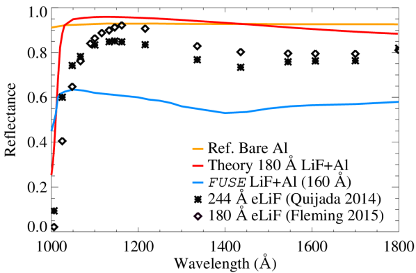
There is significant room for improvement on both the net reflectivity and hygroscopicity of LiF+Al films. Conventional physical vapor deposition (PVD) techniques yield thin film coatings of LiF with high surface roughness and low material packing densities, resulting in an absorption coefficient in the FUV approximately four orders of magnitude higher than that of bulk LiF crystal [16, 17]. This results in a peak FUV reflectivity 30 less than the theoretical reflectivity predicted by the optical constants of bulk LiF crystal and aluminum [18, 11]. Recent progress in new PVD techniques developed at the NASA Goddard Space Flight Center (GSFC) Thin Films Coating Laboratory (TFCL) have produced LiF+Al thin films with higher reflectivity in the LUV and lower surface roughness than has previously been obtained for astronomical optics [19]. These new enhanced LiF+Al coatings (eLiF) promise to reduce absorption and scatter losses, improving the bandpass and throughput for next-generation ultraviolet space observatories (Fig. 1) [20, 1].
The hygroscopic degradation of LiF can be mitigated by maintaining a dry integration and testing environment, typically with N2 purging of the instrument when not in vacuum, such as on the NASA Explorer mission [14] and on numerous sounding rocket experiments [21, 22]. For large missions such as LUVOIR, the risk associated with maintaining those measures on dozens of meter-class optics may be prohibitive, and therefore a means of permanently protecting the LiF from moisture exposure is desirable. The current “Architecture A” version of the LUVOIR Ultraviolet Multi-Object Spectrograph (LUMOS) requires a total of seven reflections (four in the telescope, three in the instrument) to image a spectrum [23]. While eLiF is currently the baseline mirror coating used in throughput calculations for LUVOIR, hygroscopic degradation of just 3 on each optical surface (the relative loss seen by the mission over instrument integration and testing [14]) would result in a 22 relative loss of LUMOS throughput. Conversely, similar gains in throughput can be realized from improved deposition processes.
In this paper, we present the first results of a study to investigate overcoating eLiF mirrors with an ultrathin (10 – 20 Å) layer of AlF3 deposited using atomic layer deposition (ALD). The AlF3 transmissive bandpass does not extend to as short of wavelengths as LiF, however at such a thin and uniform layer the effects on the overall reflectivity may be minimal, and AlF3 is believed to be more stable than LiF [24, 25]. The capping of LiF with a protective overcoat has been done before and has been shown to reduce hygroscopic degradation [13, 11, 12], however this is the first attempt using ALD. The ALD process should produce a more uniform layer with better layer thickness control than conventional evaporative processes [26, 27]. These protected eLiF samples were aged alongside bare eLiF and conventional LiF+Al samples in a set of controlled humidors at the University of Colorado (CU) Laboratory for Atmospheric and Space Physics (LASP) for a period of approximately one year. The results of these aging tests will establish the exact degradation rate of eLiF and protected eLiF with humidity exposure, providing a key parameter in assessing risk for future UV-sensitive NASA missions.
2 Film Deposition Techniques
We coated a batch of sixteen 50 75 mm fused silica slides of 1 mm thickness with target eLiF and protected eLiF layer thicknesses of 700 Å of aluminum, 160 – 180 Å of LiF, and 10 – 20 Å of AlF3 for the protected eLiF. The LiF layer thickness target was chosen to optimize the LUV reflectivity curve towards shorter wavelengths around 1060 – 1100 Å. A thicker LiF layer would raise the peak LUV reflectivity, but also move the wavelength cutoff and reflectivity peak towards longer wavelengths [13]. Depositions of eLiF were carried out at GSFC in March of 2016, with each of the 16 samples measured in the CU Square Tank facility. Three eLiF samples were then sent to JPL for the application of a protective overcoat of 10 Å AlF3 on one sample, and 20 Å AlF3 on the other two. These samples were returned to CU for re-measurement before beginning the aging experiment (§3). All samples were stored in a dry N2 purge box between deposition and aging to maintain the pristine post-coating reflectivity.
2.1 eLiF Physical Vapor Deposition
PVD is a common process for the deposition of thin films on mirrors and other surfaces. Depositions are typically carried out using either a sputtering target or via evaporation of the desired material, with LiF+Al typically carried out via evaporation. The GSFC TFCL has coated the optics of numerous astronomical, solar and earth science missions and are a leader in film deposition processes.
The deposition chamber, in this case the 1 meter diameter chamber at the TFCL [17], is evacuated to 10-6 torr and baked to outgas the materials. The chamber is left at high vacuum to cool overnight before starting the deposition process. Approximately 700 Å of aluminum is deposited at room temperature on the optic surface by running a current through aluminum coated tungsten filaments to create an aluminum vapor cloud. Shutters over the filaments control the deposition thickness by limiting the aluminum vapor exposure time. In a conventional LiF+Al deposition, 160 – 180 Å of LiF would then be applied approximately 3-5 seconds later by passing a current through a molybdenum crucible containing LiF powder and opening a separate shutter system. For small optics the LiF crucible is centered beneath the substrates, while for larger optics multiple crucibles can be spread around the chamber for higher uniformity.
The deposition of eLiF requires heating the substrate to 250 ∘C to lengthen the freeze-out time of the LiF molecules when they condense on the surface, increasing the resulting material packing density and lowering the absorption coefficient. As soon as the aluminum deposition cloud has cleared, a “flash” layer of 50 Å of conventional LiF is applied to partially protect the aluminum from oxidization as the substrate is heated. The remainder of the desired LiF thickness is applied once the substrate reaches the target temperature. Similar experiments have been carried out demonstrating increased reflectivity from LiF+Al films deposited on heated substrates, however it has never been done for an astronomical optic [16, 28].
The quality of LiF films is also dependent on the deposition rate and chamber pressure, with higher deposition rates generally resulting in higher quality films and less aluminum oxidization from the residual gas in the chamber [28, 11]. Too high of a deposition rate can result in sputtering, however, therefore the rate is a controlled parameter [19]. The depositions in this study were carried out at approximately 4 nm/s, which was determined by the GSFC TFCL to be an optimal rate for their system for conventional LiF+Al. For a more complete description of the eLiF process, see Quijada et al. 2014.
2.2 AlF3 Atomic Layer Deposition
The protection of aluminum mirrors with fluoride films deposited by ALD, which is a more controllable process than PVD, is a promising field of research for future coatings [29]. The protective fluorides typically used on astronomical optics have all been deposited to surfaces via ALD for other purposes [30, 31, 32], including LiF [33]. To date, however, there has not yet been a successful deposition of aluminum with a thin ALD overcoat that has yielded higher reflectivities than eLiF [24, 25], largely due to aluminum oxidization in the ALD chamber. While development efforts continue in the field of ALD-only mirror coatings, it is important to continue development of more conventional processes that will result in short term gains for new Explorer-class missions, and for initial LUVOIR and HabEx performance estimates. The process of depositing AlF3 via ALD onto optics was developed at the NASA Jet Propulsion Laboratory (JPL) as part of one such complimentary study into developing ALD-only mirror coatings for future missions [24, 25].
Three eLiF samples were packed in an ultra-high purity (UHP) N2 environment to preserve the pristine eLiF reflectivity and sent to JPL in April 2016 for protective AlF3 overcoating. These samples were not at risk of oxidization in the ALD chamber as the aluminum was protected already by the LiF. Coating thicknesses of approximately 10 Å and 20 Å were applied at a deposition temperature of 100 ∘C to test the dependance of reflectivity and hygroscopicity on the AlF3 layer thickness. For a description of the ALD process for AlF3 deposition, see Hennessy et al. 2016.
3 eLiF and Protected eLiF Initial Reflectivity
Unprotected eLiF coating reflectivities were measured for one sample at the GSFC TFCL after coating, and for all samples in the CU Square Tank chamber [20] on April 24th and 27th, 2016 at eight discrete hydrogen and argon spectral lines in the 973 – 1608 Å FUV bandpass.
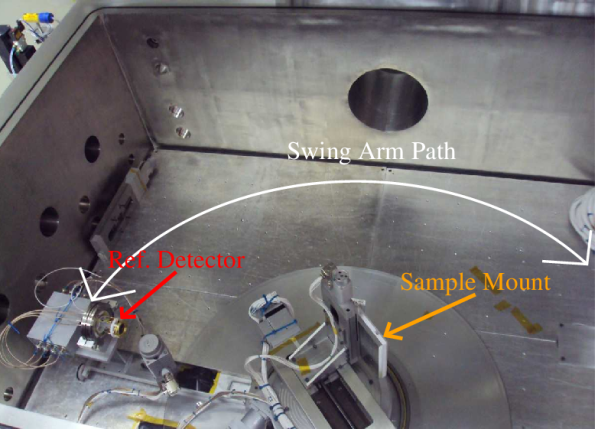
The Square Tank FUV detector is a bare Quantar microchannel plate (MCP) mounted onto a swing-arm stage with an arm length of approximately one meter. The samples are mounted at the swing arm pivot point such that the MCP is always facing the sample mount. The mount is attached to a linear vacuum stage which in turn is mounted on a rotation stage - allowing the samples to be moved in and out of the beam, and for control of the reflection angle. For all measurements the samples were held at a 7.5∘ angle relative to the incident beam, resulting in a 15∘ reflection angle.
The light source is a hollow cathode arc lamp [34] attached to a Princeton/Acton VM502 monochromator with a collimating optic at the monochromator output. The collimated, monochromatic beam is directed into the Square Tank such that it passes over the pivot point for both the swing arm and the rotation stage. The experimental setup is presented with annotations in Figure 2.
An incident light measurement is taken with the MCP in the 0∘ position and with the samples shifted out of the beam path. The beam intensity is controlled by an exit slit on the monochromator and set to 4000 counts per second for each wavelength. A standardized incident count rate reduces uncertainties due to MCP dead time between wavelengths, as well as over the course of the experiment as samples are aged. Two 10 second measurements are taken, and then a shutter is closed that blocks the beam in order to measure the system dark level (typically less than 5 of the incident intensity). The swing arm is then moved to 165∘ and the samples shifted back into the beam using the linear and rotation stages. The beam is positioned so that it is incident on the same region of the MCP for all measurements. Two reflection measurements are taken for each sample, with two dark measurements in-between, and then the system is returned to incident mode for a second set of incident measurements. The entire procedure is repeated if the incident level is found to vary by more than a few percent between the initial and final measurements for each wavelength, mitigating the effects of variability in the light source. There was a close agreement between the reflectivity determined at GSFC and the reflectivity determined at CU for the only sample measured at both locations (Sample 8, Fig. 3).

3.1 Reflectivity Pre- and Post-ALD
The initial reflectivities of the pristine eLiF optics were higher at H 1 Ly and lower at H 1 Ly than they were for a calibration sample deposited August 2015, which is presented in Figures 1 and 4 and was the target we attempted to replicate for this experiment [20]. This peaking of the reflectivity curve at shorter wavelengths is indicative of a LiF layer thinner than the optimal 1/4 of the desired peak reflectivity wavelength ( 1100 Å) within the dielectric. These samples feature a peak reflectivity around H 1 Lyman beta ( = 1026 Å), with destructive interference of the phase-shifted light reflecting off of the multilayer interfaces causing a drop in reflectivity for the rest of the FUV bandpass, centered around 1380 Å for Sample 8 (Fig. 3). Assuming the index of refraction of the LiF thin film is identical to that of bulk crystal [18], this corresponds to a layer thickness of closer to 150 Å for these samples, rather than the target of 180 Å.
| S | Ly 1026 Å | Ar 1 1067 Å | Ly 1216 Å | |||
|---|---|---|---|---|---|---|
| ReLiF | R | ReLiF | R | ReLiF | R | |
| S2 | 0.76 | —– | 0.75 | —– | 0.69 | —– |
| S51 | 0.77 | 0.79 | 0.77 | 0.77 | 0.65 | 0.73 |
| S62 | 0.81 | 0.76 | 0.80 | 0.80 | 0.71 | 0.77 |
| S7 | 0.77 | —– | 0.78 | —– | 0.72 | —– |
| S82 | 0.81 | 0.78 | 0.78 | 0.79 | 0.70 | 0.74 |
| S9 | 0.77 | —– | 0.72 | —– | 0.64 | —– |
| C13 | 0.65 | —– | 0.70 | —– | 0.73 | —– |
| C23 | 0.66 | —– | 0.70 | —– | 0.73 | —– |
1 eLiF + 10 Å AlF3
2 eLiF + 20 Å AlF3
3 Conventional LiF+Al control sample
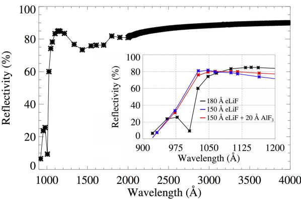
Six samples were selected for this initial aging study, with two conventional LiF+Al samples coated in November 2016 added to the study as control samples (C1 and C2). Peak reflectivity of the samples varied by 5 due to coating thickness non-uniformities inherent to the 1m TFCL deposition chamber. Of these six, three were selected for protective AlF3 overcoats at JPL such that there would be a mix of estimated eLiF layer thicknesses. Table 1 shows the initial reflectivity of each sample at H 1 Ly, Ar 1 1067 Å, and H 1 Ly, as well as the post-ALD reflectivity of the three protected eLiF samples. We found a maximum reduction in reflectivity of less than 5 at the shortest wavelength (Ly) near the LiF cutoff, and an increase in reflectivity at Ly by as much as 8. These gains are likely a result of the thickening of the total dielectric layer shifting the peak reflectivity to longer wavelengths. It is not clear what the magnitude of the reflectivity change due to the AlF3 layer would be on an optimized eLiF sample, however it is clear that the absorption at the short wavelength end will be on the order of only a few percent. This is despite the fact that both Ly and Ar 1 1067 Å are shortwards of the AlF3 cutoff. Previous studies that have employed a capping layer deposited via PVD or other evaporative processes showed larger reflective losses on the order of 10 relative to bare LiF+Al [13]. This first test of ALD deposited thin protective films over environmentally sensitive mirror coatings is therefore successful in maintaining an eLiF-like reflectivity curve (Fig. 4).
3.2 Uniformity of ALD AlF3 Layer
ALD produces highly uniform layers, which should not only provide a greater material packing density than evaporative processes, but also be mostly free of pinholes or other pathways for water vapor to contact the LiF. AlF3 films deposited via this process have been measured at JPL to have approximately 1 uniformity over similar sized wafers to those used in this study [27], however these measurements were of samples without underlying PVD film(s).
eLiF and protected eLiF samples were measured before and after AlF3 deposition using a Wyko NT2000 profilometer at the CU Keck Optics Metrology laboratory (Fig. 5) to assess whether the application of AlF3 via ALD over a PVD surface has a drastic effect on the surface morphology of the optic. This data incorporates the surface roughness of the fused silica slides ( 1), the 700 Å of aluminum, the 150 Å of LiF, and the 10 – 20 Å ALD layer; therefore it is unlikely that this thin capping layer will have any appreciable effect on the profilometry unless the AlF3 does not adhere well to the LiF and clusters or pools on the surface. We find an RMS surface roughness of 1.6 nm in the sample pre-ALD, and 1.7 nm post-ALD, which is consistant with our expectations of little to no change.
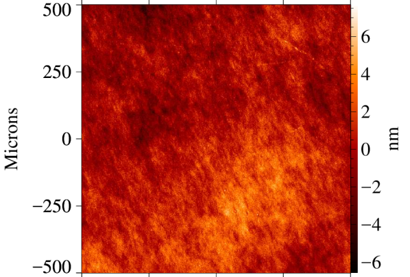
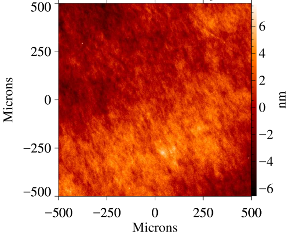
Surface features and artifacts apparent in the profilometry data of the unprotected eLiF samples are still apparent after the addition of the ALD layer, which confirms that the measurement regions in Figure 5 are identical. There are variations in the relative heights and depths between features at these scales on the order of 1-2 nm before and after the deposition of the AlF3, however it is not conclusive whether these changes are due to the ALD process or simply instrumental variability between measurements, which were taken three weeks apart. We conclude that the general topology of the samples is preserved, and that the use of ALD to protect eLiF optics does not greatly alter the surface roughness.
4 Humidity Sensitivity
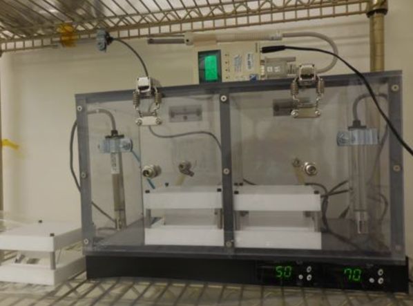
The six samples were aged for 1 year in a set of custom humidity control chambers held to 50 and 70 1 RH (Fig. 6). The two conventional LiF+Al control samples were added in November 2016 (Table 2). These RH levels were chosen as 50 is approximately the maximum ambient RH of Colorado and Southern California, while 70 represents a typical ambient humidity in Maryland or Florida. These values encompass the higher end of the range of ambient humidities seen in places where UV instruments are fabricated or launched, simulating the exposure of the optics if no protective measures were taken during an integration and testing phase.
| S | Coating | RH | Date Started |
|---|---|---|---|
| S2 | eLiF | 70 | April 27, 2016 |
| S5 | eLiF+10Å AlF3 | 70 | April 27, 2016 |
| S6 | eLiF+20Å AlF3 | 70 | April 27, 2016 |
| S7 | eLiF | 50 | April 28, 2016 |
| S8 | eLiF+20Å AlF3 | 50 | April 28, 2016 |
| S9 | eLiF | 70 | April 28, 2016 |
| C1 | LiF+Al | 70 | Nov. 24, 2016 |
| C2 | LiF+Al | 50 | Nov. 24, 2016 |
The humidors consist of a polycarbonate box fed by a balance of humidified air sourced from ultrasonic humidifiers filled with deionized water, and a soft ( 0.1 psi) UHP N2 purge [20]. Omega Hx-71 humidity probes measure the RH in each box and feed an Omega RHCN-7000 AC humidity switch. When the humidifiers are off, the low pressure N2 purge lowers the humidity in the chamber at a rate of approximately 0.5 RH per minute, depending on the ambient humidity. AC power to the humidifiers is switched on when the humidity in the box falls below a setpoint. The line pressure from the humidifier overpowers the N2 purge and raises the humidity in the chamber. This keeps the humidity in the box to 1 of the setpoint regardless of whether the ambient humidity is higher or lower than the target.
The Hx-71 probes were cross calibrated against a secondary standard calibrated by Newport Corporation. Humidity values were monitored by a LabJack U6 and logged every 30 seconds on a Raspberry Pi. The samples were stored in a teflon holder with a lid and positioned such that the coated optic faced away from the gas inlet. This required the humidified air to circulate and mix with the air in the chamber before it diffused underneath the optic cover and exposed the coated optic face, preventing direct exposure to the humidified air stream and any water vapor particles that may be carried with it. The Hx-71 gauge was positioned near the coated face of the samples (Fig. 6).
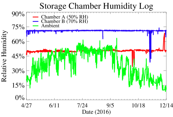
The humidor chambers were stored in a class 100,000 clean room with a filtered air supply for 383 days from April 27, 2016 (April 28th for the 50 RH chamber) until May 15, 2017. There were no deviations from the RH setpoint (save for when the chambers were opened to remove samples for measurement) for the first 187 days of the experiment, after which the 70 chamber ran low of water for 4 days (temporarily lowering the RH). Then on November 27, 2016, the humidity gauge on the 50 chamber failed, causing the humidifier to lock into an ON state for 24 hours, saturating the chamber with water vapor. This effectively ended the controlled testing for the 50 chamber. From December 2016 to May 2017, building construction disrupted the logging capability of the chambers, forcing all further humidity monitoring to be done by eye. With a few interruptions, both chambers remained at their setpoint without exceeding it. Nevertheless, we consider the experiment to be controlled only for the first 187 days, with subsequent data points suspect. The recorded humidity of each chamber for the initial 232 days, as well as the ambient humidity, is presented in Figure 7.
4.1 Sample Degradation
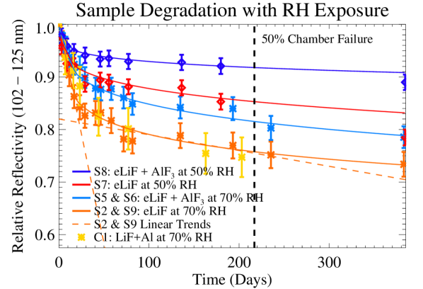
We found that the rate of degradation was similar for samples of the same type stored in the same environments. At the end of the experiment, S2 and S9 were within 3 of each other in relative degradation. Likewise, S5 and S6 were within 2 of each other, implying that there was no significant difference in protection provided by 10 Å of AlF3 relative to 20 Å. We therefore present the average degradation of similar type samples from the 70 RH chamber in Figure 8. We also include the individual 50 RH samples (S7 and S8) and the conventional LiF+Al control sample that was aged at 70 RH (C1).
The samples all show signs of degradation averaged over the LUV regardless of whether or not they are protected by AlF3. The degradation is linear for the first 10 – 15 days of exposure, with the slope dependent on both the level of RH exposure and the protection offered. The slope shallows out over time before again following a trend that can be approximated as linear, suggesting that the optics enter a semi-saturated state for a given maximum RH exposure. Unprotected eLiF stored at 50 RH degraded in LUV reflectivity by approximately 13 (relative) over 6 months of exposure, while unprotected eLiF stored at 70 RH degraded by 24 over the same time period. Both the control sample (C1) and the unprotected eLiF samples aged in consistent manners, indicating that eLiF does not in itself offer more humidity resistance than conventional LiF.
| RH (%) | Unprotected | Protected | Difference |
|---|---|---|---|
| Degradation | Degradation | ||
| 50 | 13.4 | 7.6 | 43.3 |
| 701 | 23.6 | 17.1 | 27.5 |
1 Includes both eLiF + 10 Å AlF3 and eLiF + 20
Å AlF3
The application of a thin layer of AlF3 applied by ALD offered a significant level of protection in both chambers, with LUV degradations of approximately 8 and 17 for the 50 and 70 samples, respectively. This represents 43 and 28 less reflectivity loss for samples stored in identical environments. These results are captured in Table 3.
5 Discussion of Results
The rate of degradation of LiF-based optics under exposure to constant humidity slows over time. For the purposes of easily estimating the risk to astronomical optics during instrument integration and testing, we have approximated the degradation rate using two linear functions: one over a 15 day period and the other for an extended level of exposure of 30 days, with a curved transition in-between. We find that the degradation slows by roughly an order of magnitude after the initial 15 day exposure, suggesting a partial saturation. The linear-fit degradation rates per hour of exposure are presented in Table 4.
| Coating | RH (%) | Rate (t 350h) | Rate (t 600h) |
|---|---|---|---|
| eLiF | 50 | 1.39 10-4 | 1.06 10-5 |
| eLiF+AlF3 | 50 | 0.76 10-4 | 0.42 10-5 |
| eLiF | 70 | 3.47 10-4 | 1.25 10-5 |
| eLiF+AlF31 | 70 | 2.13 10-4 | 1.30 10-5 |
1 Includes both eLiF + 10 Å AlF3 and eLiF + 20 Å AlF3
5.1 Potential Moisture Sensitivity of AlF3
AlF3 was selected for these initial ALD tests because it has the closest bandgap to LiF of the other potential mirror coatings in use, and because it is considered hydrophilic, not hygroscopic. The incomplete protection of the samples to humidity exposure suggests that it is possible water molecules penetrated the ALD layer to some degree and degraded the underlying eLiF. It may be that AlF3 provides complete resistance to RH exposure, but that the surface chemistry of the ALD process is not compatible with eLiF and monolayers are not evenly formed. The slower degradation of protected eLiF relative to unprotected eLiF may simply reflect the coverage percentage of the ALD layer. The ALD process should produce a more uniform and denser film than PVD, however, and the similar performance of both the 10 Å and 20 Å AlF3 overcoats aged at 70 RH suggest that pinholes or incomplete coverage are unlikely to be the cause of the sample degradation. More testing with a technique with higher resolution than a profilometer, such as atomic force microscopy (AFM), is necessary to prove this.
AlF3 is a relatively new material for mirror coatings that has never been used in an astronomical instrument, and this is the first controlled test of an AlF3-based mirror at sustained humidities 50 [12, 25]. Given the paucity of experience with AlF3, it is also possible that the incomplete protection of the eLiF optics is due to unexpected moisture absorption by the AlF3 overcoat directly. It is known that LiF stored in dry environments such as RH 25 desiccator boxes, can last years with no evidence of degradation [35, 22], therefore our results suggest that there is an “activation humidity” under which hygroscopic materials do not react significantly enough to noticeably degrade. Previous tests of AlF3+Al robustness may not have breeched this threshold for an appreciable amount of time, and therefore show no indication of significant degradation.
That the hygroscopic degradation rate changes non-linearly with RH exposure is not new and has been noted in previous experiments. In Angel et al. 1961, LiF+Al was found to degrade by approximately 2 at H 1 Ly when stored for two months at laboratory conditions of roughly 40 RH, but more rapidly for RH 50 [13]. They also suggested and tested overcoating LiF with thin capping layers of approximately 15 Å of MgF2 applied via conventional (not ALD) means. This lowered the initial reflectivity by 10. They found that four days of aging at 50 RH led to a 22 degradation of the unprotected LiF+Al optic, and 2 degradation for the protected optic.
If we were to assume that the degradation over six months as a function of maximum RH exposure was a linear function, which is likely an oversimplification given only two RH levels tested, we would derive the following relationships for eLiF and AlF3 protected eLiF:
These relationships both would reach the point of 0 degradation in the 20 – 40 RH range, with eLiF at 23.5 (consistent with storage in an RH 25 desiccator box) and protected eLiF at 34. This would put protected eLiF in the humidity range typical ESD (electrostatic discharge) clean rooms are held at (32 – 40), suggesting that a humidity controlled clean room and modest purge procedures may be enough to preserve protected LiF-based optics. A wider range of humidities would establish this relationship better and identify the maximum safe humidity for these coatings. We have added two additional humidity control chambers set to 25 and 40 RH for future tests.
5.2 Resistance to Catastrophic Exposure
The failure of the 50 storage chamber provides an opportunity to assess the response of the coatings to short-term catastrophic moisture exposure. There were three samples in the 50 chamber when the Hx-71 gauge failed, setting the humidifier into an ON state for approximately 24 hours. During this time, the chamber reached humidities beyond the local dew point, resulting in water droplets forming on all surfaces. In addition to S7 and S8, the chamber contained a control sample (C2) that was added to the chamber in a pristine state less than three days before the gauge failure. This provides a serendipitous opportunity to compare the durability of eLiF and protected eLiF in the semi-saturated state (S7 and S8, respectively) to unprotected LiF in a pristine state (C2) when exposed to humidities higher than the local dew point.
Both semi-saturated samples exhibit a small but significant drop in reflectivity as a result of direct exposure to highly humidified air, with the protected eLiF sample dropping by about half the relative reflectivity of the unprotected sample (Table 5). This suggests that the protected sample was more resistant to very high RH exposure and condensation than unprotected eLiF. The control sample drops by a much more significant 20 relative reflectivity, indicating that pristine optics (albeit conventional LiF+Al, not eLiF) are more sensitive to catastrophic exposure than optics in the semi-saturated state. C2 was aged in the 50 chamber for the remainder of the experiment and was measured periodically, during which time it degraded at a similar rate as the semi-saturated unprotected eLiF did before the chamber failure (1.04 10-5 per hour). The brief exposure to very high humidity led to significant reflectivity losses, but once humidity was restored it aged the same as the other semi-saturated unprotected samples.
| Sample | Coating | Ref. Prior | Ref. After | R |
|---|---|---|---|---|
| S7 | eLiF | 66.5 | 61.2 | 8.0 |
| S8 | eLiF+AlF3 | 71.8 | 69.4 | 3.3 |
| C21 | LiF+Al | 69.8 | 55.8 | 20.0 |
1 Pristine - only aged 3 days before chamber failure
6 Conclusions and Future Work
The protection of eLiF from hygroscopic degradation by applying an ultrathin (10 – 20 Å) overcoat of AlF3 via ALD was shown to reduce the reflectivity degradation at FUV wavelengths, though it did not provide complete hygroscopic immunity at the 50 RH environments explored in this study. This matches similar results from previous studies that have capped LiF with a protective overcoat [13, 11], though this is the first study to apply the capping layer with ALD, and to age at controlled humidity levels. The protected eLiF samples each degraded 28 – 43 less than unprotected eLiF when stored in identical environments over a six month to one year timescale. Protected eLiF also showed greater resistance to catastrophic exposure to water vapor on the timescale of a few hours relative to unprotected eLiF. The application of the protective overcoat resulted in only a minimal attenuation of the eLiF reflectivity curve beyond the AlF3 cutoff of 1070 Å, which was possibly due more to the increase in the net dielectric layer thickness than to attenuation by the AlF3.
Complete protection of the LiF layer coupled with further improvements in the deposition process could make protected eLiF the standard coating for all UV-sensitive observatories in the near future. Reflectivity peaks of greater than 90 at H 1 Ly have already been realized with thicker coatings, matching the performance of MgF2 at that wavelength while still providing LUV sensitivity not possible with other protected aluminum coatings [19]. Additional investment in the eLiF process optimization could lead to greater gains, as eLiF reflectivities remain 5 – 10 below the theoretical maximum estimated from bulk LiF crystal optical constants (Fig. 1).
We are currently preparing to expand this first ALD trial by protecting eLiF with MgF2, rather than AlF3. The success of the AlF3 ALD process on maintaining the eLiF reflectivity implies that similar success may be possible with MgF2 - a material with far more flight and laboratory heritage than AlF3. We have also obtained AlF3 + Al optic samples coated via a similar high temperature PVD process at GSFC to determine the hygroscopic sensitivity, if any, of AlF3 in a controlled setting. This test will enable us to determine whether the degradation seen in our AlF3-protected eLiF samples was due to incomplete protection, or intrinsic moisture sensitivity in AlF3 films.
For this next project phase we have constructed two additional humidity control chambers that will operate at 25 and 40 RH to test for an “activation humidity” to fluoride degradation (§5.5.1). If it can be shown that there is a humidity floor below which hygroscopic degradation is not an issue, then it may be possible to move away from the extreme protection measures utilized successfully on and other projects with LiF mirror coatings. This will make it easier to estimate the cost and risk associated with using hygroscopic optical coatings on future NASA Explorer and large missions. We have also developed a new vacuum measurement chamber designed specifically for high cadence, highly repeatable reflectivity measurements for more efficient monitoring of sample aging [36].
Another advantage of eLiF is that unlike the ALD process or other advanced conceptual coating strategies, unprotected eLiF can be applied in the same GSFC deposition chambers that coated the optics and numerous other NASA missions. This enables a rapid path to flight qualification and TRL advancement. In collaboration with the GSFC TFCL, The CU/LASP ultraviolet sounding rocket program is preparing to fabricate and launch the Sub-orbital Imaging Spectrograph for Transition-region Irradiance from Nearby Exoplanet host stars (SISTINE) sounding rocket payload, which will serve as a flight test platform for eLiF-based optical coatings [1]. SISTINE will feature a 0.5 m primary mirror coated in unprotected eLiF, as the JPL ALD chambers cannot currently accomodate large optics, while the secondary and fold mirrors will be overcoated at JPL with a protective layer of AlF3 or MgF2 to demonstrate both eLiF variants in a working instrument. Tests are ongoing at CU to determine whether ion etched holographic gratings are compatible with high temperature deposition processes. The coating of these flight optics will take place in early 2018 with a target launch date in 2019. SISTINE is designed to serve as a platform for flight testing any new advanced LUV mirror coating developed in the next few years, supporting rapid flight qualification of this critical technology.
Protected eLiF mirror coatings currently provide the highest total LUV reflectivity from 1000 – 1150 Å with less humidity sensitivity than unprotected eLiF. Reflectivities of 75 throughout the 1040 – 4000 Å bandpass ( 85 for 2500 Å) have been demonstrated on bare eLiF, with peak LUV reflectivities of 85. While this first run of protected samples underperformed those previous results due to an overly thin eLiF layer, protected eLiF is still the closest of any existing mirror coating to meeting the technical requirements of the LUVOIR project [6]. Further improvements in the eLiF deposition process are underway at GSFC, while experiments with MgF2 protected eLiF may offer even greater resilience, making protected eLiF the most advanced mirror coating for LUV-sensitive space observatories currently available.
7 Funding Information
This work was funded by a Nancy Grace Roman Technology Fellowship in Astrophysics awarded by the National Aeronautics and Space Administration (NASA) with grant number NNX15AF27G. The process development to apply AlF3 via ALD was performed at the Jet Propulsion Laboratory, California Institute of Technology, under a contract with NASA. The authors would like to thank the anonymous reviewers for providing helpful comments.
©2017 Optical Society of America. One print or electronic copy may be made for personal use only. Systematic reproduction and distribution, duplication of any material in this paper for a fee or for commercial purposes, or modifications of the content of this paper are prohibited.
References
- [1] B. T. Fleming, K. France, N. Nell, N. Kruczek, R. Kane, J. Green, M. A. Quijada, J. Del Hoyo, and O. Siegmund, “SISTINE: a pathfinder for FUV imaging spectroscopy on future NASA astrophysics missions,” Proc. SPIE 9905, 99050A (2016).
- [2] D. V. Bowen, E. B. Jenkins, T. M. Tripp, and D. G. York, “On VI Absorption in the Milky Way Disk, and Future Prospects for Studying Absorption at the Galaxy-IGM Interface,” in “American Institute of Physics Conference Series,” , vol. 1135, M. E. van Steenberg, G. Sonneborn, H. W. Moos, and W. P. Blair, eds. (2009), pp. 85–93.
- [3] J. Tumlinson, A. Aloisi, G. Kriss, K. France, S. McCandliss, K. Sembach, A. Fox, T. Tripp, E. Jenkins, M. Beasley, C. Danforth, M. Shull, J. Stocke, N. Lehner, C. Howk, C. Froning, J. Green, C. Oliveira, A. Fullerton, B. Blair, J. Kruk, G. Sonneborn, S. Penton, B. Wakker, X. Prochaska, J. Vallerga, and P. Scowen, “Unique Astrophysics in the Lyman Ultraviolet,” ArXiv e-prints (2012).
- [4] K. France, E. Shkolnik, J. Linsky, A. Roberge, T. Ayres, T. Barman, A. Brown, J. Davenport, J.-M. Desert, S. Domagal-Goldman, B. Fleming, J. Fontenla, L. Fossati, C. Froning, G. Hallinan, S. Hawley, R. Hu, L. Kaltenegger, J. Kasting, A. Kowlaski, P. Loyd, P. Mauas, Y. Miguel, R. Osten, S. Redfield, S. Rugheimer, C. Schneider, A. Segura, J. Stocke, F. Tian, J. Tumlinson, M. Vieytes, L. Walkowicz, B. Wood, and A. Youngblood, “Characterizing the Habitable Zones of Exoplanetary Systems with a Large Ultraviolet/Visible/Near-IR Space Observatory,” ArXiv e-prints (2015).
- [5] J. Dalcanton, S. Seager, S. Aigrain, S. Battel, N. Brandt, C. Conroy, L. Feinberg, S. Gezari, O. Guyon, W. Harris, C. Hirata, J. Mather, M. Postman, D. Redding, D. Schiminovich, H. P. Stahl, and J. Tumlinson, “From Cosmic Birth to Living Earths: The Future of UVOIR Space Astronomy,” ArXiv e-prints (2015).
- [6] M. R. Bolcar, K. Balasubramanian, J. Crooke, L. Feinberg, M. Quijada, B. J. Rauscher, D. Redding, N. Rioux, S. Shaklan, H. P. Stahl, C. M. Stahle, and H. Thronson, “Technology gap assessment for a future large-aperture ultraviolet-optical-infrared space telescope,” Journal of Astronomical Telescopes, Instruments, and Systems 2, 041209 (2016).
- [7] K. France, R. O. Parke Loyd, A. Youngblood, A. Brown, P. C. Schneider, S. L. Hawley, C. S. Froning, J. L. Linsky, A. Roberge, A. P. Buccino, J. R. A. Davenport, J. M. Fontenla, L. Kaltenegger, A. F. Kowalski, P. J. D. Mauas, Y. Miguel, S. Redfield, S. Rugheimer, F. Tian, M. C. Vieytes, L. M. Walkowicz, and K. L. Weisenburger, “The MUSCLES Treasury Survey. I. Motivation and Overview,” ApJ 820, 89 (2016).
- [8] B. Mennesson, S. Gaudi, S. Seager, K. Cahoy, S. Domagal-Goldman, L. Feinberg, O. Guyon, J. Kasdin, C. Marois, D. Mawet, M. Tamura, D. Mouillet, T. Prusti, A. Quirrenbach, T. Robinson, L. Rogers, P. Scowen, R. Somerville, K. Stapelfeldt, D. Stern, M. Still, M. Turnbull, J. Booth, A. Kiessling, G. Kuan, and K. Warfield, “The Habitable Exoplanet (HabEx) Imaging Mission: preliminary science drivers and technical requirements,” in “Space Telescopes and Instrumentation 2016: Optical, Infrared, and Millimeter Wave,” Proc. SPIE 9904, 99040L (2016).
- [9] S. N. Osterman, E. Wilkinson, J. C. Green, and K. W. Redman, “FUV grating performance for the cosmic origins spectrograph,” in “UV, Optical, and IR Space Telescopes and Instruments,” Proc. SPIE 4013, 360–366 (2000).
- [10] S. R. McCandliss, B. Fleming, M. E. Kaiser, J. Kruk, P. D. Feldman, A. S. Kutyrev, M. J. Li, P. A. Goodwin, D. Rapchun, E. Lyness, A. D. Brown, H. Moseley, O. Siegmund, and J. Vallerga, “Fabrication of FORTIS,” Proc. SPIE 7732 (2010).
- [11] S. Wilbrandt, O. Stenzel, H. Nakamura, D. Wulff-Molder, A. Duparré, and N. Kaiser, “Protected and enhanced aluminum mirrors for the VUV,” Appl. Opt.53, A125 (2014).
- [12] K. Balasubramanian, J. Hennessy, N. Raouf, S. Nikzad, M. Ayala, S. Shaklan, P. Scowen, J. Del Hoyo, and M. Quijada, “Aluminum mirror coatings for UVOIR telescope optics including the far UV,” in “Optics for EUV, X-Ray, and Gamma-Ray Astronomy VII,” Proc. SPIE 9602, 96020I (2015).
- [13] D. W. Angel, W. R. Hunter, R. Tousey, and G. Hass, “Extreme ultraviolet reflectance of LiF-coated aluminum mirrors,” J. Opt. Soc. Am. 51, 913–914 (1961).
- [14] R. G. Ohl, R. H. Barkhouser, S. J. Conard, S. D. Friedman, J. Hampton, H. W. Moos, P. Nikulla, C. M. Oliveira, and T. T. Saha, “Performance of the Far Ultraviolet Spectroscopic Explorer mirror assemblies,” in “Instrumentation for UV/EUV Astronomy and Solar Missions,” Proc. SPIE 4139, 137–148 (2000).
- [15] J. C. Green, E. Wilkinson, and S. D. Friedman, “Design of the Far Ultraviolet Spectroscopic Explorer spectrograph,” in “X-Ray and Ultraviolet Spectroscopy and Polarimetry,” Proc. SPIE 2283, 12–19 (1994).
- [16] M. R. Adriaens and B. Feuerbacher, “Improved LiF and MgF2 overcoated aluminum mirrors for vacuum ultraviolet astronomy,” Appl. Opt.10, 958 (1971).
- [17] M. A. Quijada, S. Rice, and E. Mentzell, “Enhanced MgF2 and LiF over-coated Al mirrors for FUV space astronomy,” Proc. SPIE 8450 (2012).
- [18] H. H. Li, “Refractive index of alkali halides and its wavelength and temperature derivatives,” Journal of Physical and Chemical Reference Data 5, 329–528 (1976).
- [19] M. A. Quijada, J. del Hoyo, and S. Rice, “Enhanced far-ultraviolet reflectance of MgF2 and LiF over-coated al mirrors,” in “Space Telescopes and Instrumentation 2014: Ultraviolet to Gamma Ray,” Proc. SPIE 9144 (2014).
- [20] B. T. Fleming, M. A. Quijada, K. France, K. Hoadley, J. Del Hoyo, and N. Kruczek, “New UV instrumentation enabled by enhanced broadband reflectivity lithium fluoride coatings,” in “UV, X-Ray, and Gamma-Ray Space Instrumentation for Astronomy XIX,” Proc. SPIE 9601, 96010R (2015).
- [21] K. France, N. Nell, K. Hoadley, R. Kane, E. B. Burgh, M. Beasley, R. Bushinksy, T. B. Schultz, M. Kaiser, C. Moore, J. Kulow, and J. C. Green, “Flight performance and first results from the sub-orbital local interstellar cloud experiment (SLICE),” in “UV, X-Ray, and Gamma-Ray Space Instrumentation for Astronomy XVIII,” Proc. SPIE 8859, 885910 (2013).
- [22] K. Hoadley, K. France, N. Kruczek, B. Fleming, N. Nell, R. Kane, J. Swanson, J. Green, N. Erickson, and J. Wilson, “The re-flight of the Colorado high-resolution Echelle stellar spectrograph (CHESS): improvements, calibrations, and post-flight results,” Proc. SPIE 9905, 99052 (2016).
- [23] K. France, B. Fleming, G. West, S. R. McCandliss, M. R. Bolcar, W. Harris, L. Moustakas, J. M. O’Meara, I. Pascucci, J. Rigby, D. Schiminovich, J. Tumlinson, J.-C. Bouret, C. J. Evans, and M. Garcia, “The LUVOIR Ultraviolet Multi-Object Spectrograph (LUMOS): instrument definition and design,” Proc. SPIE 10397, 22 (2017).
- [24] C. S. Moore, J. Hennessy, A. D. Jewell, S. Nikzad, and K. France, “Recent developments and results of new ultraviolet reflective mirror coatings,” Proc. SPIE 9144, 4 (2014).
- [25] J. Hennessy, K. Balasubramanian, C. S. Moore, A. D. Jewell, S. Nikzad, K. France, and M. Quijada, “Performance and prospects of far ultraviolet aluminum mirrors protected by atomic layer deposition,” Journal of Astronomical Telescopes, Instruments, and Systems 2, 041206 (2016).
- [26] R. W. Johnson, A. Hultqvist, and S .F. Bent, “A brief review of atomic layer deposition: From fundamentals to applications,” Materials Today, 17, 236–246 (2014).
- [27] J. Hennessy, A. D. Jewell, K. Balasubramanian, and S. Nikzad, “Ultraviolet optical properties of aluminum fluoride thin films deposited by atomic layer deposition,” Journal of Vacuum Science & Technology A: Vacuum, Surfaces, and Films 34, 01A120 (2016).
- [28] E. T. Hutcheson, G. Hass, and J. T. Cox, “Effect of deposition rate and substrate temperature on the vacuum ultraviolet reflectance of MgF2 and LiF-overcoated aluminum mirrors,” Applied Optics 11, 2245–2248 (1972).
- [29] J. Hennessy, A. D. Jewell, F. Greer, M. C. Lee, and S. Nikzad, “Atomic layer deposition of magnesium fluoride via bis(ethylcyclopentadienyl)magnesium and anhydrous hydrogen fluoride,” Journal of Vacuum Science & Technology A: Vacuum, Surfaces, and Films 33, 01A125 (2015).
- [30] T. Pilvi, M. Ritala, M. Leskelä, M. Bischoff, U. Kaiser, and N. Kaiser, “Atomic layer deposition process with TiF4 as a precursor for depositing metal fluoride thin films,” Applied Optics 47, C271–C274 (2008)
- [31] Y. Lee, H. Sun, M. J. Young, S. M. George, “Atomic Layer Deposition of Metal Fluorides Using HF–Pyridine as the Fluorine Precursor,” Chem. Mater. 28, 2022–-2032 (2016)
- [32] M. F. J. Vos, H. C. M. Knoops, R. A. Synowicki, W. M. M. Kessels, and A. J. M. Mackus, “Atomic layer deposition of aluminum fluoride using Al(CH3)3 and SF6 plasma,” Applied Physics Letters 111, 113105 (2017).
- [33] M. Mäntymäki, J. Hämäläinen, E. Puukilainen, T. Sajavaara, M. Ritala, and M. Leskelä, “Atomic Layer Deposition of LiF Thin Films from Lithd, Mg(thd)2, and TiF4 Precursors,” Chem. Mater. 25, 1656–1663 (2013).
- [34] W. G. Fastie and D. E. Kerr, “Spectroradiometric calibration techniques in the far ultraviolet - A stable emission source for the Lyman bands of molecular hydrogen,” Applied Optics 14, 2133–2142 (1975).
- [35] C. M. Oliveira, K. Retherford, S. J. Conard, R. H. Barkhouser, and S. D. Friedman, “Aging studies of LiF-coated optics for use in the far ultraviolet,” in “EUV, X-Ray, and Gamma-Ray Instrumentation for Astronomy X,” Proc. SPIE 3765, 52–60 (1999).
- [36] J. Wiley, B. Fleming, N. Renninger, A. Egan, “Semi-automated high-efficiency reflectivity chamber for vacuum UV measurements,” Proc. SPIE 10397, 9 (2017).