∎
Tel.: +1-505-667-3386
22email: scotthsu@lanl.gov 33institutetext: Y. C. Francis Thio 44institutetext: HyperJet Fusion Corporation, Chantilly, VA 20151
Tel: +1-301-524-4698
44email: francis.thio@hyperjetfusion.com
Physics Criteria for a Subscale Plasma Liner Experiment††thanks: This work was supported in part by the U.S. Department of Energy under contract no. DE-AC52-06NA25396.
Abstract
Spherically imploding plasma liners, formed by merging hypersonic plasma jets, are a proposed standoff driver to compress magnetized target plasmas to fusion conditions [S. C. Hsu et al., IEEE Trans. Plasma Sci. 40, 1287 (2012)]. In this paper, the parameter space and physics criteria are identified for a subscale, plasma-liner-formation experiment to provide data, e.g., on liner ram-pressure scaling and uniformity, that are relevant for addressing scientific issues of full-scale plasma liners required to achieve fusion conditions. Based on these criteria, we quantitatively estimate the minimum liner kinetic energy and mass needed, which informed the design of a subscale plasma liner experiment now under development.
Keywords:
Plasma liners Plasma jets Magneto-inertial fusion1 Introduction
Ongoing research hsu18 on the Plasma Liner Experiment (PLX) hsu12pop ; hsu15jpp is aiming to demonstrate the formation and implosion of spherical plasma liners via merging hypersonic plasma jets formed by pulsed coaxial guns (where “hypersonic” refers to the jets being highly supersonic and where atomic excitation, ionization, and radiative effects are important bertin13 ). The guns, jets, and imploding plasma liner constitute a driver to compress a magnetized plasma target to fusion conditions, i.e., a proposed embodiment of magneto-inertial fusion (MIF) lindemuth83 ; kirkpatrick95 ; lindemuth09 known as plasma-jet-driven magneto-inertial fusion (PJMIF) thio99 ; thio01 ; hsu12ieee ; knapp14 . PJMIF has several attributes making it a potential candidate for an economically viable, repetitively pulsed fusion reactor coststudy17 . An immediate, near-term objective is to retire the major physics risks associated with the plasma-liner-driver aspects of PJMIF at the lowest-possible cost and technical risk.
The key goal of PJMIF development during the present three-year research phase (ending in 2019) is to demonstrate the formation, viability, and scalability of spherically imploding plasma liners formed by merging plasma jets. Specifically, an objective is to obtain experimental data on two key scientific issues of the plasma liner as an MIF compression driver: (1) scaling of peak ram pressure () of the plasma liner versus initial plasma jet parameters and number of jets, and (2) evolution and control of non-uniformities seeded by the jet-merging process, which have the potential to degrade the ability of a plasma liner to compress a target plasma to fusion conditions.
Because the overall cost of a plasma-liner-formation experiment is closely linked to the initial stored energy, we were motivated to conduct a careful analysis of the minimum stored energy required to address PJMIF-relevant, plasma-liner issues in a meaningful way. The required stored energy is determined by two independent properties: (1) the electrical efficiency of the plasma guns, and (2) the required minimum initial kinetic energy of the imploding plasma liner. This paper is restricted to consideration of the latter. The analysis is based on first identifying key physics criteria that must be satisfied in order for a subscale experiment to provide data that is relevant for a full-scale, fusion-relevant plasma liner. Based on these criteria, we then quantitatively estimate the minimum initial plasma-liner kinetic energy and mass of a subscale experiment that satisfies the fusion-relevant plasma-liner criteria.
A full-scale PJMIF plasma liner thio99 ; hsu12ieee would consist of an array of, perhaps, hundreds of coaxial plasma guns uniformly mounted around a spherical chamber that is several meters in radius. It is envisioned hsu12ieee that a small subset of the guns fires first to form a magnetized plasma target, followed immediately by the remainder of the guns firing to form a spherically imploding plasma liner that compresses the target. The physical processes and steps of plasma-liner formation via merging plasma jets, the subsequent convergence of the liner, and scalings of peak liner ram pressure and non-uniformity evolution have been studied extensively and presented elsewhere thio99 ; thio01 ; parks08 ; samulyak10 ; awe11 ; hsu12ieee ; davis12 ; hsu12pop ; cassibry12 ; kim12 ; merritt13 ; cassibry13 ; kim13 ; merritt14 ; langendorf17pop , though much more research is needed to validate the PJMIF concept.
A key issue for PJMIF is the required/achievable symmetry of the imploding plasma liner; this is being addressed in ongoing research hsu18 . Prior numerical studies cassibry12 ; kim13 employed 3D simulations to elucidate the origin and evolution of non-uniformities seeded by shocks that form between discrete merging jets. Results based on 3D smooth-particle hydrodynamic (SPH) simulations by Cassibry et al. cassibry12 indicated that late-time uniformity of a plasma liner formed with discrete jets was similar to that of an initially spherically symmetric liner, which is a favorable result. However, further simulations are needed to explore the effects of spatial resolution (i.e., number of particles in the simulation) and the value of artificial viscosity on the liner symmetry and its evolution. Kim et al. kim13 , using a 3D hydrodynamics code, provided a physical picture of plasma-liner formation via merging plasma jets and liner-uniformity evolution. These simulations predicted that “primary” shocks would form between adjacent merging jets, and then the shocked plasmas associated with the “primary shocks” would merge to form “secondary shocks.” This physical picture has been verified in experiments hsu18 . However, in these parameter regimes, shock strength is over-predicted in single-fluid hydrodynamics codes. Further benchmarking studies, along with new 3D simulations of plasma-liner formation via the merging of up to hundreds of plasma jets, will be reported elsewhere. Indeed, a key objective of ongoing research hsu18 is to work toward setting requirements on and identifying limits of achievable liner uniformity.
Another key issue for PJMIF is the need to develop compatible targets that take advantage of the high implosion speed ( km/s) of a spherically imploding plasma liner. Some discussions of PJMIF-relevant target formation have appeared elsewhere ryutov09 ; hsu12ieee ; welch14 , but much further research on PJMIF-compatible target development is needed. As described by D. Ryutov ryutov09 , an interesting target for compression is a high- (i.e., ) object with a “tangled field” that, simultaneously, allows for reduced cross-field thermal transport (i.e., Hall parameter ) and adequate parallel electron thermal confinement time (due to the long connection length of the tangled field). Because , it is expected that the issue of magnetohydrodynamic (MHD) instability would be sidestepped entirely because there is not enough free energy in the magnetic field to instigate virulent global instabilities. D. Ryutov ryutov09 lays out detailed requirements for such a target to satisfy the above properties but recognizes that creation of such a target plasma “may not be a simple task.” He also states that “an intuitively appealing way for creating such a target would be the use of numerous plasma guns generating small-scale, magnetized plasma bunches and injection of such bunches into a limited volume.” This is precisely the plan which we intend to pursue in the near future. The high implosion speed ( km/s) of a spherically imploding plasma liner, enabling the compression of a several-cm-radius plasma target in s, is what enables the possibility of near-adiabatic heating of such a novel, high- plasma target.
The remainder of the paper is organized as follows. Section 2 presents PJMIF reactor-relevant plasma-liner parameters in order to identify the relevant physics criteria for a subscale experiment. Section 3 concisely states these criteria. Section 4 uses the criteria to derive the minimum liner kinetic energy and mass for a relevant subscale experiment. Finally, Sec. 5 summarizes the main results of the paper.
2 PJMIF reactor-relevant plasma-liner parameters
We start by considering the PJMIF reactor-relevant parameter regime. Table 1 summarizes the desired physical parameters of the target at stagnation and the imploding spherical plasma liner at the time of peak . The peak target thermal pressure at stagnation is limited by the peak liner . One-dimensional radiation-hydrodynamic simulations aimed at reaching the conditions in Table 1 have shown fusion energy gains up to 30 knapp14 , where the gain is defined as the fusion energy divided by the initial liner kinetic energy. Similar cases were studied further using a 1D semi-analytic model of PJMIF langendorf17pop . These promising configurations were originally identified through hundreds of 1D simulations by one of the authors.
| parameter | target (DT) | liner (Xe) | liner (Kr) | liner (Ar) |
|---|---|---|---|---|
| pressure (Mbar) | ||||
| mass density (g/cm3) | 0.02 | 3.06 | 3.06 | 3.06 |
| ion density (cm-3) | ||||
| velocity (km/s) | 0 | 70 | 70 | 70 |
| compressed target radius (cm) | 0.4 | |||
| Mach number | 36 | 29 | 20 |
The required plasma-liner conditions at the time of peak dictate the plasma-jet initial conditions as well as the range of plasma-liner parameters over the entire implosion from the jet-merging radius down to the stagnation radius , which are connected through the following relations,
| (1) |
and
| (2) |
where and are the liner mass density and ion number density at , respectively, the liner mass density just prior to reaching , the total liner mass, the liner kinetic energy at , the liner implosion speed (assumed to be constant from to just before ), the liner thickness at , and the atomic mass of the liner species. Note that Eq. (1) holds strictly only for a 1D steady-state convergent flow with constant and constant polytropic index . In a real plasma-liner system, these assumptions are not expected to hold exactly; nevertheless, Eq. (1) provides an adequate method for our present need to obtain an approximate relationship between and .
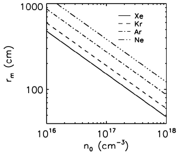
Using g/cm3 and cm from Table 1, then Eq. (1) gives g/cm. Using the latter and setting MJ, then kg and cm. Equation (2) shows that is fixed once , , and are fixed. Figure 1 plots versus for Xe, Kr, Ar, and Ne (ion-to-proton mass ratios , 83.80, 39.95, and 20.17, respectively), showing that we are limited to Xe and Kr liners if we restrict ourselves to m and cm-3.
We proceed with estimating the important plasma, equation-of-state (EOS), and hydrodynamic quantities of this reference PJMIF scenario. We focus on the use of xenon in assessing the PJMIF reactor-relevant regime because xenon gives the highest for a given and the highest Mach number (where is the ion sound speed) for given and .
2.1 Liner plasma-physics properties
2.1.1 Collisionality
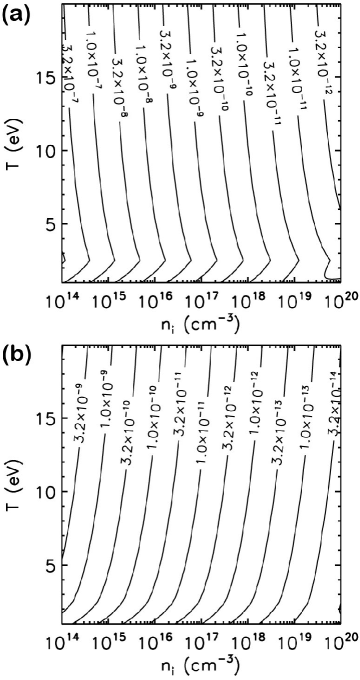
The thermal ion and electron collision times, and , respectively, in the plasma liner, for a range of relevant ( assumed) and ion density from down to , are shown in Fig. 2 for xenon. The jogs in the contours are due to a transition from () to () when exceeds 2.5 eV (up to a temperature at which xenon becomes fully stripped). The relation is a convenient way to model increasing with rising drake10 . In contrast, exhibits a milder jog at the same transition. Figure 2 shows that the plasma liner is very collisional from down to , with ns and ns for the entire evolution (assuming that remains above cm-3 and remains below 10 eV). The ion–electron energy equilibration time is . For most of the liner evolution, s (for cm and km/s), meaning that is a good approximation. The only exception is right at jet merging when the ions are shock heated over a microsecond time scale when the liner is at relatively low density, in which case s for cm-3 and –10 eV. However, should likely be restored long before stagnation. The degree of separation between and due to ion shock heating is the focus of ongoing research hsu18 and will be reported further elsewhere. The key conclusion here is that a reactor-relevant plasma liner is highly collisional for its entire evolution.
2.2 Liner equation-of-state and radiative properties
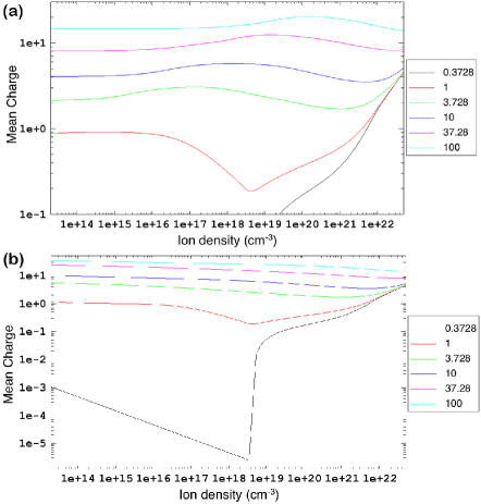
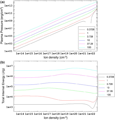
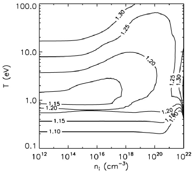
Non-local-thermodynamic-equilibrium (non-LTE) EOS and opacity tables are used to infer the EOS (Figs. 3–4), opacity [Fig. 5(a)], and radiative-cooling [Fig. 5(b)] properties of a reactor-relevant xenon plasma liner for parameters spanning to . The tables were generated using PROPACEOS macfarlane06 , an EOS and opacity code with detailed configuration accounting. Of particular interest is the value of in the xenon liner over the range of plasma-liner parameters spanning to . Using the non-LTE EOS table, we evaluate for xenon using the relationship zeldovich
| (3) |
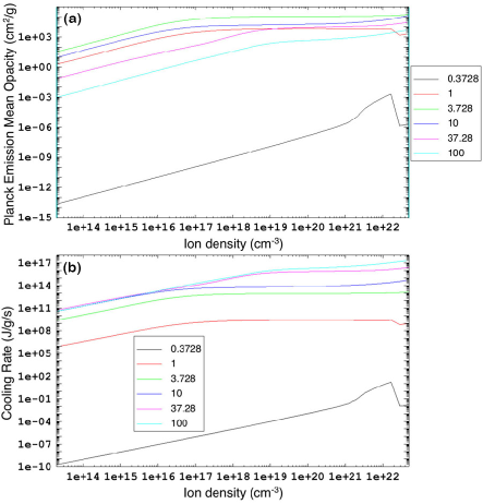
where is the total internal energy including both thermal and ionization/excitation energies, and show the results in Fig. 6. Equation (3) shows that a larger for given and will bring closer to unity (i.e., below of an ideal gas); a decrease of below 5/3 is a measure of the extra energy sinks due to ionization and atomic excitation (and associated line radiation) over that of an ideal gas. Figure 6 shows that for the entire range of (assuming ) and , and in particular for the most-relevant range of –10 eV during plasma-liner convergence, . This is desirable in order to keep the plasma liner cold and to maintain a high during convergence, as discussed in Sec. 2.3.1. The same EOS/opacity tables are also used as input to 1D radiation-hydrodynamic simulations of spherically imploding plasma liners, which are described in Sec. 2.3.2. Although the opacity [Fig. 5(a)] and radiative-cooling [Fig. 5(b)] data are not used explicitly in the analyses in this paper, they are used in the simulation of a plasma-liner implosion in Sec. 2.3.2 and are included here for reference.
2.3 Hydrodynamic properties
2.3.1 Mach number
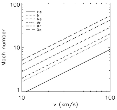
Because the peak liner ram pressure is expected to scale as awe11 ; davis12 , it is desirable to achieve high , which will also reduce the amount of jet spreading and density degradation as the jets propagate from the guns to langendorf17pop . Achieving in a subscale experiment is a reasonable criterion to be in a physics regime that is relevant to a reactor-relevant plasma liner. Figure 7 shows (as defined in Sec. 2) versus liner implosion speed for different species. For helium, km/s is needed for , but for nitrogen (and heavier elements), km/s (or lower for heavier elements) is sufficient.
2.3.2 Simulation
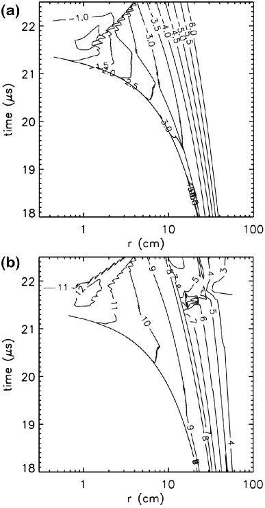
To develop knowledge of the plasma-liner parameters from to , we used HELIOS macfarlane06 , a 1D radiation-hydrodynamic code, to simulate an imploding 1.62-cm-thick xenon plasma liner, starting at cm with spatially uniform km/s, cm-3, and eV. Note that this simulation does not include a magnetized target; it is a xenon liner imploding on vacuum. The simulation uses non-LTE xenon EOS/opacity data [Figs. 3(a), 4, and 5] generated using PROPACEOS, includes thermal and radiation transport, and allows and to evolve separately. The liner is modeled using 300 computational zones (i.e., an average of 54 m/zone at the initial time step). Figure 8 shows the temporal and spatial evolution of and , the peak values of which are 0.72 g/cc and 26.7 Mbar, respectively, at s and cm. Optimization of liner parameters and profiles, e.g., see kagan11 , is needed in order to achieve the desired peak ram pressure of 150 Mbar at the same initial kinetic energy.
3 Physics criteria to be satisfied in a subscale plasma liner experiment
The results in Sec. 2 guide us to the important physics criteria that must be satisfied in a subscale plasma liner experiment to be of relevance to the full-scale reactor-relevant plasma liner. We state them as follows:
-
•
at
-
•
plasma must be collisional for the entire duration from to , i.e.,
-
•
effective of the liner species should be as is the case for xenon.
4 Requirements for a subscale plasma liner experiment
We use Eq. (2) to estimate and of a subscale plasma liner experiment that satisfies the physics criteria stated in Sec. 3. Rather than fixing as we did for the PJMIF-reactor scenario, we use the criteria stated in Sec. 3 and the constraints of the PLX vacuum chamber and near-term plasma guns to set , , , , and , picking the lowest allowed values for each quantity in order to minimize and of a subscale experiment.
First, we determine , which is given by (and plotted in Fig. 9) cassibry13
| (4) |
where is the initial jet radius, the initial jet Mach number, the chamber-wall radius (where jets are launched), and the number of jets. Equation (4) includes the effect of jet spreading at the maximum rate , where is the sound speed, and thus provides an upper bound on . We choose cm as an upper bound, corresponding to and (see Fig. 9). Lower and higher will result in lower and therefore lower .
To determine , we assume that the initial jet length equals at . Upgrades to pulsed coaxial guns witherspoon09 for the subscale plasma-liner-formation experiments were expected to achieve cm (and indeed recently have done so case17aps ), and thus we use cm.
The minimum at is determined based on satisfying the collisionality requirement , i.e.,
where we have used (nitrogen), eV, km/s, , , and cm. Thus, we set to strongly satisfy the collisionality requirement. Note that if rises during liner convergence, the minimum requirement will decrease due to the scaling (where, again, is used as a simple model for ionization).
For , we refer to Fig. 7 to see that we must have km/s to have for nitrogen, which is the lowest-mass element being considered that will allow us to get while staying well below km/s.
Finally, using Eq. (3) and a PROPACEOS non-LTE nitrogen EOS, we verify that for a nitrogen plasma liner so as to have the desirable energy sink from ionization and atomic excitation to keep high, as exhibited by xenon (Fig. 6). Figure 10(a) shows that a nitrogen plasma liner in a subscale experiment would have for the most-relevant range of –10 eV. Argon, which is also being used extensively in the subscale experiment, has for the same range [Fig. 10(b)].
With the values cm, cm, cm-3, km/s, and nitrogen as the liner species, Eq. (2) tells us that kJ and mg. To obtain scaling data in the subscale experiment with species up to xenon would require nearly a factor of ten higher mass (15.4 mg) and energy (19.7 kJ). To further scale up an order of magnitude or up by a factor of three (or some combination thereof) would require another factor of ten higher in energy, resulting in kJ for the ideal subscale plasma-liner-formation experiment, capable of a decade in energy scaling for the heaviest element xenon.
Due to budgetary constraints, the subscale plasma-liner-formation experiment now being developed hsu18 is expected to culminate with guns and total capacitor stored energy of kJ. For and , Fig. 9 shows that cm. Using km/s and cm, Eq. (2) gives kJ for xenon. If the gun electrical efficiency is (as suggested by the ongoing work case17aps ; hsu18 ), then the maximum liner energy is kJ, meaning there is still a reasonable factor of 4.5 headroom above kJ (xenon) for scaling studies. Lower-mass species would have a higher headroom in energy for scaling studies.
5 Summary
We laid out the key requirements of a subscale plasma-liner-formation experiment to produce data of direct relevance for addressing key scientific issues of a full-scale, reactor-relevant plasma liner. The key scientific issues of plasma-liner formation via merging hypersonic plasma jets being addressed in the near term are: (1) determining the scaling of peak liner ram pressure with initial plasma-jet parameters, and (2) assessing liner non-uniformity and prospects for non-uniformity control.
To ensure that a subscale plasma-liner-formation experiment can address the above issues in a way that is relevant to the full-scale plasma liner, we identified key physics criteria that must be satisfied in the subscale experiment. These criteria are: (1) the plasma liner must be very collisional all the way from the merging radius to stagnation, (2) the liner Mach number must be high, i.e., , (3) the liner species must satisfy while possessing the EOS and radiative properties, i.e., , of a high- species such as Xe, as desired in a fusion-relevant liner.
A thirty-six-gun experiment with liner kinetic energy up to kJ that satisfies the physics criteria and requirements presented in this paper is now under development hsu18 .
Acknowledgements.
The authors acknowledge many fruitful discussions with Drs. F. Douglas Witherspoon and Jason Cassibry, and also the U.S. Department of Energy Advanced Research Projects Agency–Energy (ARPA-E), whose launch of the Accelerating Low-cost Plasma Heating and Assembly (ALPHA) Program motivated this work. Strong Atomics, LLC, is acknowledged for supporting HyperJet Fusion Corporation’s contributions to the subscale plasma liner experiment under development.References
- (1) S.C. Hsu, S.J. Langendorf, K.C. Yates, J.P. Dunn, S. Brockington, A. Case, E. Cruz, F.D. Witherspoon, M.A. Gilmore, J.T. Cassibry, R. Samulyak, P. Stoltz, K. Schillo, W. Shih, K. Beckwith, Y.C.F. Thio, IEEE Trans. Plasma Sci. PP(99), 1 (2017). DOI 10.1109/TPS.2017.2779421
- (2) S.C. Hsu, E.C. Merritt, A.L. Moser, T.J. Awe, S.J.E. Brockington, J.S. Davis, C.S. Adams, A. Case, J.T. Cassibry, J.P. Dunn, M.A. Gilmore, A.G. Lynn, S.J. Messer, F.D. Witherspoon, Phys. Plasmas 19, 123514 (2012)
- (3) S.C. Hsu, A.L. Moser, E.C. Merritt, C.S. Adams, J.P. Dunn, S. Brockington, A. Case, M. Gilmore, A.G. Lynn, S.J. Messer, F.D. Witherspoon, J. Plasma Phys. 81, 345810201 (2015)
- (4) J.J. Bertin, R.M. Cummings, Aerodynamics for Engineers, Sixth Edition (Pearson, Upper Saddle River, NJ, 2013)
- (5) I.R. Lindemuth, R.C. Kirkpatrick, Nucl. Fusion 23, 263 (1983)
- (6) R.C. Kirkpatrick, I.R. Lindemuth, M.S. Ward, Fusion Tech. 27, 201 (1995)
- (7) I.R. Lindemuth, R.E. Siemon, Amer. J. Phys. 77, 407 (2009)
- (8) Y.C.F. Thio, E. Panarella, R.C. Kirkpatrick, C.E. Knapp, F. Wysocki, P. Parks, G. Schmidt, in Current Trends in International Fusion Research–Proceedings of the Second International Symposium, ed. by E. Panarella (NRC Canada, Ottawa, 1999), p. 113
- (9) Y.C.F. Thio, C.E. Knapp, R.C. Kirkpatrick, R.E. Siemon, P.J. Turchi, J. Fusion Energy 20, 1 (2001)
- (10) S.C. Hsu, T.J. Awe, S. Brockington, A. Case, J.T. Cassibry, G. Kagan, S.J. Messer, M. Stanic, X. Tang, D.R. Welch, F.D. Witherspoon, IEEE Trans. Plasma Sci. 40, 1287 (2012)
- (11) C.E. Knapp, R.C. Kirkpatrick, Phys. Plasmas 21, 070701 (2014)
- (12) “Conceptual Cost Study for a Fusion Power Plant Based on Four Technologies from the DOE ARPA-E ALPHA Program,” Bechtel National, Inc., Report No. 26029-000-30R-G01G-00001 (2017).
- (13) P.B. Parks, Phys. Plasmas 15, 062506 (2008)
- (14) R. Samulyak, P. Parks, L. Wu, Phys. Plasmas 17, 092702 (2010)
- (15) T.J. Awe, C.S. Adams, J.S. Davis, D.S. Hanna, S.C. Hsu, J.T. Cassibry, Phys. Plasmas 18, 072705 (2011)
- (16) J.S. Davis, S.C. Hsu, I.E. Golovkin, J.J. MacFarlane, J.T. Cassibry, Phys. Plasmas 19, 102701 (2012)
- (17) J.T. Cassibry, M. Stanic, S.C. Hsu, F.D. Witherspoon, S.I. Abarzhi, Phys. Plasmas 19, 052702 (2012)
- (18) H. Kim, R. Samulyak, L. Zhang, P. Parks, Phys. Plasmas 19, 082711 (2012)
- (19) E.C. Merritt, A.L. Moser, S.C. Hsu, J. Loverich, M. Gilmore, Phys. Rev. Lett. 111, 085003 (2013)
- (20) J.T. Cassibry, M. Stanic, S.C. Hsu, Phys. Plasmas 20, 032706 (2013)
- (21) H. Kim, L. Zhang, R. Samulyak, P. Parks, Phys. Plasmas 20, 022704 (2013)
- (22) E.C. Merritt, A.L. Moser, S.C. Hsu, C.S. Adams, J.P. Dunn, A. Miguel Holgado, M.A. Gilmore, Phys. Plasmas 21, 055703 (2014)
- (23) S.J. Langendorf, S.C. Hsu, Phys. Plasmas 24, 032704 (2017)
- (24) D.D. Ryutov, Fus. Sci. Tech. 56, 1489 (2009)
- (25) D.R. Welch, T.C. Genoni, C. Thoma, D.V. Rose, S.C. Hsu, Phys. Plasmas 21, 032704 (2014)
- (26) R.P. Drake, High-Energy-Density-Physics (Springer-Verlag, Berlin, 2010)
- (27) J.J. MacFarlane, I.E. Golovkin, P.R. Woodruff, J. Quant. Spect. Rad. Transfer 99, 381 (2006)
- (28) Y.A. Zel’dovich, Y.P. Raizer, Physics of Shock Waves and High-Temperature Hydrodynamic Phenomena (Academic Press, New York, 1966)
- (29) G. Kagan, X. Tang, S.C. Hsu, T.J. Awe, Phys. Plasmas 18, 120702 (2011)
- (30) F.D. Witherspoon, A. Case, S.J. Messer, R. Bomgardner II, M.W. Phillips, S. Brockington, R. Elton, Rev. Sci. Instrum. 80, 083506 (2009)
- (31) A. Case, S. Brockington, E. Cruz, F.D. Witherspoon, Bull. Amer. Phys. Soc. 62, 395 (2017)