Saturation of the hosing instability in quasi-linear plasma accelerators
Abstract
The beam hosing instability is analyzed theoretically for a witness beam in the quasi-linear regime of plasma accelerators. In this regime, the hosing instability saturates, even for a monoenergetic bunch, at a level much less than standard scalings predict. Analytic expressions are derived for the saturation distance and amplitude and are in agreement with numerical results. Saturation is due to the natural head-to-tail variations in the focusing force, including the self-consistent transverse beam loading.
pacs:
41.75.-i,41.75.Jv,52.38.KdThe beam hosing instability is a major concern for both conventional accelerators and plasma-based accelerators. In both cases, this instability can exponentially amplify the small misalignments between the beam and the accelerating structure, and potentially lead to a strong degradation of the beam emittance, or even to complete disruption of the beam. Thus the hosing instability (which is related to the well-known beam-breakup instability) has been actively studied in its various regimes Lau (1989). This includes the long-bunch, weakly-coupled regime Neil et al. (1979); Whittum (1997) applicable to low-current bunches in conventional accelerators, as well as the long-bunch Panofsky and Bander (1968); Whittum et al. (1991); Schroeder et al. (2012) and short-bunch Chao et al. (1980); Geraci and Whittum (2000); Dodd et al. (2002); Schroeder et al. (1999); Mehrling et al. (2017); Huang et al. (2007) strongly-coupled regimes, which are of interest for beams propagating in plasmas or ion channels.
In particular, the short-bunch, strongly-coupled regime is relevant to the evolution of the witness beam in plasma-wakefield acceleration (both for the beam-driven and laser-driven scheme). In this case, the exponential growth of the hosing instability as a function of the acceleration distance has raised concerns regarding the feasibility of a plasma-based particle collider Lebedev et al. (2016). However, these predictions have been made in the context of the blow-out (or bubble) wakefield regime, i.e. when the driver (beam or laser) is strong enough to expell all the plasma electrons, forming a co-moving ion cavity Mora and Thomas M. Antonsen (1997); Rosenzweig et al. (1991); Pukhov and Meyer-ter Vehn (2002); Lu et al. (2006); Tzoufras et al. (2008). Plasma accelerators may also operate in the quasi-linear regime, where the driver excites a plasma density perturbation that is a fraction of the background plasma density Esarey et al. (2009). In this Letter, we show that the sustained exponential growth of the hosing instability, which indeed applies for monoenergetic beams in the blow-out regime, does not occur in the quasi-linear regime. Instead, in the quasi-linear regime, the instability can rapidly saturate, and leads only to a moderate amplification of the beam misalignment.
This early saturation is due to the head-to-tail spread in betatron frequency that naturally occurs across the bunch in the quasi-linear regime. It is indeed well-known that a head-to-tail spread in betatron frequency can mitigate the hosing instability Lau (1989); Balakin et al. (1983). However, in the blow-out regime, the focusing force of the wakefield is independent of the longitudinal coordinate, and thus any head-to-tail spread in betatron frequency necessarily requires an energy spread in the bunch. Owing to the typically large beam-loading for high efficiency, large energy spreads (e.g. a few percents Mehrling et al. (2017)) are required Lebedev et al. (2016). This is impractical, since many applications of plasma-wakefield accelerators require monoenergetic beams. By contrast, in the quasi-linear regime, the focusing force naturally varies as a function of the longitudinal coordinate, and moreover this variation can potentially be tailored by beam loading Katsouleas et al. (1987). Therefore, in the quasi-linear regime, no energy spread is required in order to mitigate the hosing instability.
Hosing equation - In order to study the hosing instability, let us consider the equation of evolution for the centroid of the witness beam. For simplicity, the effects of beam acceleration are not considered here, but can be obtained by a simple change of variable Chernin and Mondelli (1989); Schroeder et al. (1999) [i.e. by replacing, in Eq. (1) below, by and by ]. Under these assumptions, the transverse evolution of the centroid is governed by the equation
| (1) | |||||
where is the propagation distance, and is the head-to-tail coordinate (by convention here, corresponds to the head of the witness bunch, and thus this bunch extends in the region ), is the bunch density at position , and is the plasma density. Physically, the left-hand side of Eq. (1) is the equation of motion in a purely cylindrically symmetric wakefield, while the right-hand side captures the asymmetric perturbations to the wakefield, which are driven by the transverse offset of the beam (e.g. Schroeder et al. (2012); Huang et al. (2007)). The expression of the coefficients , and depend on the wakefield regime considered.
For instance, in the blow-out regime Huang et al. (2007), Eq. (1) applies with , and (assuming a uniform bunch density ), where is the plasma wavevector, and are the radius and Lorentz factor of the monoenergetic witness beam, is the radius of the blown-out cavity, and the coefficient (given in Huang et al. (2007)) takes into account the relativistic nature of the electron sheath. In this regime and for a monoenergetic bunch, there are no head-to-tail variations of the betatron frequency, i.e. is independent of .
On the other hand, in the quasi-linear regime (and for a witness beam having a transverse flat-top profile with ), Eq. (1) applies with , and
| (2) | |||||
where the first term corresponds to the transverse wakefield generated by the driver (either a laser or a charged particle bunch) and the second term corresponds to transverse beam loading by the witness beam Katsouleas et al. (1987). In the above expression, is the average longitudinal position of the driver and is the amplitude of the transverse driver wakefield. For example, in the case of a flat-top electron bunch driver with a density , radius , and length , this amplitude is , where is the modified Bessel function. In case of a linearly-polarized Gaussian laser pulse with an amplitude , a waist , and an RMS duration , . From Eq. (2), it is clear that exhibits head-to-tail variations, even for a monoenergetic beam. As shown below, these variations can lead to a saturation of the hosing instability.
Analytical solution for a linear chirp - In the general case, the system Eqs. (1)-(2) can only be solved numerically. However, in order to gain insight into the saturation mechanism, we first study Eq. (1) analytically, in the simplified case of a linear betatron head-to-tail chirp and uniform beam density:
| (3) |
where is constant and quantifies the betatron chirp. Note that, although we will eventually apply this analytical solution to the case of a quasi-linear wakefield, we keep the generic notations and from Eq. (1) here, so that the analysis can be applied to other similar situations (e.g. blow-out regime with linear energy chirp).
For small betatron chirps (), we find that standard Laplace transform and steepest descents techniques can be applied to find . Starting for instance from a uniform initial offset , asymptotic solutions can be found for the early stage and late stage of the hosing instability, where the transition between these two asymptotic solutions is determined by a characteristic length
| (4) |
(See the Supplementary Material for a derivation of these solutions.) For (early stage), the asymptotic solution is given by
| (5) |
and corresponds to the well-known scaling of the hosing instability, whereby the amplitude of the betatron oscillations grows exponentially with .
On the other hand, for (late stage), the form of the solution depends on the sign of . For (increasing betatron frequency from tail to head), the solution is given by
| (6) | |||
| (9) |
and corresponds to betatron oscillations that have a constant, saturated amplitude. For (decreasing frequency from tail to head), the solution is given by
and corresponds to betatron oscillations that initially decrease as [first term in Eq. (Saturation of the hosing instability in quasi-linear plasma accelerators)] and eventually saturate at a low level [second term in Eq. (Saturation of the hosing instability in quasi-linear plasma accelerators)].
We note that Chernin and Mondelli (1989); Stupakov (1997) considered beam-breakup in conventional accelerators, and that similar analytical solutions were found in the case of a wakefield function that is linear in (i.e. where the function in Eq. (1) is replaced by a linear function.) However this short-beam linear wakefield function does not properly describe plasma accelerators where, typically, .
The asymptotic solutions Eqs. (Saturation of the hosing instability in quasi-linear plasma accelerators), (6) and (Saturation of the hosing instability in quasi-linear plasma accelerators) are compared with the explicit numerical integration of the hosing equation Eq. (1) in Fig. 1, for (left panels) and (right panels). As expected, in both cases the numerical solution (black curve) is initially in agreement with the standard scaling Eq. (Saturation of the hosing instability in quasi-linear plasma accelerators) (red curve). For longer propagation distances, the instability saturates and is in good agreement with Eq. (6) and Eq. (Saturation of the hosing instability in quasi-linear plasma accelerators), respectively (blue curves). Additionally, Eq. (4) correctly predicts the approximate position of the transition between the early-stage and late-stage regimes (vertical dashed lines).
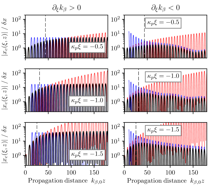
Thus, positive and negative chirps ( and ) exhibit qualitatively different behaviors, but both strongly mitigate the hosing instability (compared to the case with no chirp). In these cases, using the standard scaling Eq. (Saturation of the hosing instability in quasi-linear plasma accelerators) – which does not take into account this mitigation – can lead to an overestimation of the instability by an order of magnitude, or more. Qualitatively, this is because a betatron chirp causes the different slices of the bunch to progressively dephase and disrupts their coherent contribution to the instability after a length . Note that the scaling cannot be obtained from a coarse two-particle model Chao et al. (2013).
We note that the qualitative behavior for , whereby the amplitude of the oscillations initially increases but later decreases, is consistent with the behavior shown in Mehrling et al. (2017), where the authors observed, in numerical simulations, that the deceleration of the tail of driver bunch (which induces ) in the blow-out regime could cause a similar decrease in amplitude.
Quasi-linear wakefield with optimal beam loading - Let us now connect the simplified case of a linear betatron chirp (Eq. (3)) with the more generic case of the quasi-linear wakefield (Eq. (2)). Here we will consider the important case where is constrained by optimal beam loading. In order to produce monoenergetic beams, it is indeed desirable to tailor the beam density so as to flatten the accelerating field. The accelerating force on a narrow witness electron beam () is given by Katsouleas et al. (1987)
| (11) | |||
where is the amplitude of the longitudinal driven wakefield. For example, for a flat-top electron bunch driver, and for a Gaussian laser pulse. In these conditions, it is well-known Katsouleas et al. (1987) that optimal beam-loading (i.e. uniform accelerating field) is obtained for a triangular-shaped witness bunch, with (in our notation)
| (12) |
Inserting this expression into the equations for the accelerating force (Eq. (11)) and the betatron frequency (Eq. (2)) yields
| (13) | |||
| (14) |
According to Eq. (14), in the case of optimal beam loading, the form of the head-to-tail variations of depends on the ratio of the transverse and longitudinal driven wakefield , and thus on the shape of the driver. For instance, for (which occurs e.g. for a narrow bunch driver with a radius equal to that of the witness beam ), the second term in Eq. (14) vanishes, and so is simply linear in , with a slope proportional to . Note that, in the accelerating phase of the wakefield, , and thus this situation corresponds to the regime . On the other hand, for (which is usually the case for a Gaussian laser driver, or a wide bunch driver) the variations of are more complicated, with changing sign from head to tail.
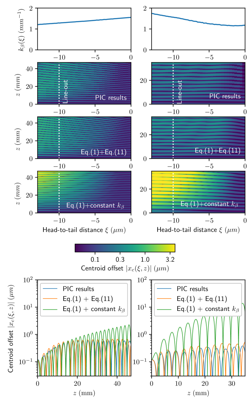
In order to illustrate these two situations, we carried out Particle-In-Cell (PIC) simulations with (a) a bunch driver having a radius (which corresponds to , and thus ) and (b) a laser driver having (which corresponds to , and thus in most of the bunch). For simplicity, we disabled driver evolution in the simulations, and imposed a driver velocity . (This is valid for acceleration distances shorter than the characteristic lengthscale of driver evolution, which is on the order of for a beam driver with a normalized emittance , and on the order of the dephasing length for a guided laser driver.) In both simulations (which used ), a witness beam with was initialized with a longitudinal density given by Eq. (12) (i.e. optimal beam loading), and a transverse Kapchinskij-Vladimirskij distribution Lund et al. (2009) with a radius and which was matched to as given by Eq. (14) (thereby ensuring that the transverse density profile remains close to flat-top throughout the simulation). In order to seed the hosing instability, the witness bunch was shifted transversally by an initial uniform offset . The simulations were performed with the spectral quasi-cylindrical code FBPIC Lehe et al. (2016) using the azimuthal modes and . (This is sufficient because the fields of the unperturbed, symmetrical beam are entirely contained in the mode , and because the perturbations due to the small offset create additional contributions in the modes with a typical amplitude Schroeder et al. (2012). Thus, if is small compared to , the relevant physics can be captured by the leading order, i.e. the mode .) In the simulations, the cell size was and , the timestep was chosen such that , and the background plasma was represented with 8 macroparticles per cell (which was sufficient to reach numerical convergence, as ascertained by separate tests featuring 32 macroparticles per cell).
The PIC simulation results are shown in the upper panels of Fig. 2. As expected from the analysis of Eq. (14), the betatron frequency exhibits head-to-tail variations in both cases (top plots). This causes the instability to quickly saturate as a function of in the PIC simulations (upper colormaps, showing that the maximum centroid offset reaches only a limited value on the logarithmic colorscale), in a way that is consistent with the numerical integration of the equation of hosing Eq. (1) with given by Eq. (14) (middle colormaps). Importantly, the level of the instability is much lower than it would have been in the case of a uniform (lower colormaps, reaching higher values on the logarithmic colorscale). This can also be seen on the line-outs of the colormaps at a fixed position (bottom plots), which, again, show that the PIC simulations and Eq. (1) with Eq. (14) are in agreement regarding the amplitude of the centroid oscillations (some differences occur because Eq. (1) neglects beam acceleration and the evolution of the transverse beam profile), and that this amplitude is lower than that predicted by Eq. (1) with a constant . This confirms that, in the quasi-linear regime, the hosing instability is less severe than suggested by the standard scalings (e.g. Eq. (Saturation of the hosing instability in quasi-linear plasma accelerators)) that assume a uniform .
In conclusion, we showed that, in the quasi-linear regime of plasma acceleration, the hosing instability is strongly mitigated, even for a monoenergetic bunch. This is due to the natural variations of the focusing forces across the bunch, and happens both for increasing and decreasing head-to-tail variations. In the case of optimal beam loading, the exact form of these head-to-tail variations is controlled by the shape of the driver.
Acknowledgements.
This work was supported by the Director, Office of Science, Office of High Energy Physics, of the U.S. Department of Energy under Contract No. DE-AC0205CH11231. Simulations were performed on the Lawrencium computational cluster resource provided by the IT Division at the Lawrence Berkeley National Laboratory (Supported by the Director, Office of Science, Office of Basic Energy Sciences, of the U.S. Department of Energy under Contract No. DE-AC02-05CH11231).References
- Lau (1989) Y. Y. Lau, Phys. Rev. Lett. 63, 1141 (1989).
- Neil et al. (1979) V. K. Neil, L. S. Hall, and R. K. Cooper, Part. Accel. 9, 213 (1979).
- Whittum (1997) D. H. Whittum, J. Phys. A 30, 8751 (1997).
- Panofsky and Bander (1968) W. K. H. Panofsky and M. Bander, Review of Scientific Instruments 39, 206 (1968).
- Whittum et al. (1991) D. H. Whittum, W. M. Sharp, S. S. Yu, M. Lampe, and G. Joyce, Phys. Rev. Lett. 67, 991 (1991).
- Schroeder et al. (2012) C. B. Schroeder, C. Benedetti, E. Esarey, F. J. Grüner, and W. P. Leemans, Phys. Rev. E 86, 026402 (2012).
- Chao et al. (1980) A. W. Chao, B. Richter, and C.-Y. Yao, Nuclear Instruments and Methods 178, 1 (1980).
- Geraci and Whittum (2000) A. A. Geraci and D. H. Whittum, Physics of Plasmas 7, 3431 (2000).
- Dodd et al. (2002) E. S. Dodd, R. G. Hemker, C.-K. Huang, S. Wang, C. Ren, W. B. Mori, S. Lee, and T. Katsouleas, Phys. Rev. Lett. 88, 125001 (2002).
- Schroeder et al. (1999) C. B. Schroeder, D. H. Whittum, and J. S. Wurtele, Physical Review Letters 82, 1177 (1999).
- Mehrling et al. (2017) T. J. Mehrling, R. A. Fonseca, A. Martinez de la Ossa, and J. Vieira, Phys. Rev. Lett. 118, 174801 (2017).
- Huang et al. (2007) C. Huang, W. Lu, M. Zhou, C. E. Clayton, C. Joshi, W. B. Mori, P. Muggli, S. Deng, E. Oz, T. Katsouleas, M. J. Hogan, I. Blumenfeld, F. J. Decker, R. Ischebeck, R. H. Iverson, N. A. Kirby, and D. Walz, Physical Review Letters 99, 255001 (2007).
- Lebedev et al. (2016) V. Lebedev, A. Burov, and S. Nagaitsev, Reviews of Accelerator Science and Technology 09, 187 (2016).
- Mora and Thomas M. Antonsen (1997) P. Mora and J. Thomas M. Antonsen, Physics of Plasmas 4, 217 (1997), http://dx.doi.org/10.1063/1.872134 .
- Rosenzweig et al. (1991) J. B. Rosenzweig, B. Breizman, T. Katsouleas, and J. J. Su, Phys. Rev. A 44, R6189 (1991).
- Pukhov and Meyer-ter Vehn (2002) A. Pukhov and J. Meyer-ter Vehn, Applied Physics B 74, 355 (2002).
- Lu et al. (2006) W. Lu, C. Huang, M. Zhou, W. B. Mori, and T. Katsouleas, Phys. Rev. Lett. 96, 165002 (2006).
- Tzoufras et al. (2008) M. Tzoufras, W. Lu, F. S. Tsung, C. Huang, W. B. Mori, T. Katsouleas, J. Vieira, R. A. Fonseca, and L. O. Silva, Phys. Rev. Lett. 101, 145002 (2008).
- Esarey et al. (2009) E. Esarey, C. B. Schroeder, and W. P. Leemans, Rev. Mod. Phys. 81, 1229 (2009).
- Balakin et al. (1983) V. E. Balakin, A. V. Novokhatsky, and V. P. Smirnov, Proceedings, 12th International Conference on High-Energy Accelerators, HEACC 1983: Fermilab, Batavia, August 11-16, 1983, Conf. Proc. C830811, 119 (1983).
- Katsouleas et al. (1987) T. C. Katsouleas, S. Wilks, P. Chen, J. M. Dawson, and J. J. Su, Part. Accel. 22, 81 (1987).
- Chernin and Mondelli (1989) D. Chernin and A. Mondelli, Part. Accel. 24, 177 (1989).
- Stupakov (1997) G. V. Stupakov, SLAC report SLAC-AP-108 (1997).
- Chao et al. (2013) A. Chao, K. Mess, M. Tigner, and F. Zimmermann, Handbook of Accelerator Physics and Engineering (World Scientific Publishing Company, 2013).
- Lund et al. (2009) S. M. Lund, T. Kikuchi, and R. C. Davidson, Phys. Rev. ST Accel. Beams 12, 114801 (2009).
- Lehe et al. (2016) R. Lehe, M. Kirchen, I. A. Andriyash, B. B. Godfrey, and J.-L. Vay, Computer Physics Communications 203, 66 (2016).