Toward the measurement of the hyperfine structure of muonic hydrogen in the FAMU experiment.
Abstract
We consider a simplified model of the optical multi-pass cavity that is being currently developed by the FAMU collaboration for the measurement of the hyperfine splitting in the ground state of muonic hydrogen and of the Zemach radius of the proton. The model is focused on the time distribution of the events of laser-stimulated hyperfine transitions in the muonuc atom and may be helpful in the preliminary design of the FAMU experimental set-up and, more generally, in the optimization of multi-pass optical cavities for experiments with pulsed lasers.
1 Introduction
The laser excitation of the ortho hyperfine sub-level of the ground state of the muonic hydrogen atom from the para sub-level (where is the total spin of the muonic hydrogen atom ) is an ambitious project of the FAMU collaboration famu-coll : the measurement of the resonance transition frequency will provide top-accuracy data on the Zemach radius of the protonfamu-exp . This is a very weak M1 magnetic dipole transition with probability of only for laser pulse energy , laser beam cross section and target temperature NIMB12 , for which an optical multi-pass cavities needs to be used to enhance the probability of laser-stimulated transitions to a reasonable level.
The measurement of the hyperfine splitting in the ground state of muonic hydrogen consists in the detailed study of the chain of processes occurring when muonic hydrogen atoms in a mixture of hydrogen and oxygen interact with laser radiation tuned at a frequency around the hyperfine transition resonance frequency NIMB12 . The observable quantity used as signature is the time distribution of the events of muon transfer from hydrogen to oxygen famu-mutran recognized by the emission of characteristic X-rays : the maximal deviation of the latter from the background time distribution in absence of laser indicates that the laser source is tuned at the resonance frequency.
The FAMU experiment will use the pulsed muon source of the RIKEN-RAL muon facility riken-ral , a tunable pulsed mid-infrared laser in the 6.8 m range famu-laser , and a multi-pass cavity with mirrors of very high reflectance. The work on the optimization of the experimental set-up showed that in experiments with pulsed sources the time distribution of the laser energy in the multi-pass cavity is of primary importance. We present here a simplified model of the phenomena in this case that allows to qualitatively determine the optimal parameters of the cavity in dependence of the laser pulse parameters. Particular attention is paid to the optimal choice of the measurement time gate, i.e. the time interval in which the time distributions of the characteristic X-rays with and without laser are to be observed.
2 Modelling the time profile of the electromagnetic fields in a multi-pass cavity
2.1 Preliminary remarks
The probability for the excitation of the ortho hyperfine ground state of with a oscillating magnetic field of resonance frequency in the time interval such that , under the condition that the width of the laser line is smaller that the Doppler broadening of the hyperfine transition line, can be put in the form:
| (1) |
where is the amplitude of the magnetic field carried by the laser plane wave at the position of the atom, and the value of the dimension coefficient is expressed in terms of the masses and magnetic moments of the proton and the muon, the temperature and NIMB12
| (2) |
Accordingly, the probability that a para-to-ortho transition will occur in the elemental volume (i.e. the expected number of laser-stimulated spin-flip events) is
| (3) |
where is the number density of atoms. At distances of the order of the wave length , the amplitude itself varies much faster than the atomic density , so we consider the probability , obtained from by averaging over a volume such that :
| (4) |
where is the amplitude of the magnetic field averaged at the wavelength scale. Denote by the number of laser-stimulated spin-flip events that occur in the volume during the measurement time interval :
| (5) |
and by – the number of events in the whole cavity (of which, in the general case, only part of which is irradiated by the laser source). For uniform muonic atom density this yields
| (6) |
In a multi-pass cavity the oscillating magnetic field at is the incoherent sum of the magnetic fields carried by the multiple reflected laser beams that irradiate the point :
| (7) |
where , and are the amplitude, phase and wave vector of the -th plane wave, all of them with the same and . It can be shown for two summands that (where is the angle between and , , and is the smoothing volume of Eq.(4)); the latter is directly extended to any number of plane waves crossing at non-zero angles:
| (8) |
2.2 A simple mathematical model of the multi-pass cavity
We shall consider a simplified model of the multi-pass cavity aimed at qualitatively reproducing only the time dependence of . The evaluation of the spatial distribution of the spin-flip events requires specific simulation codes and the detailed knowledge of the -atom number density spatial distribution that are out of the scope of this talk; accordingly, we adopt the approximation of uniform number density of the muonic atoms, assume to be the whole cavity volume , and consider only the time distribution of .
We assume that the cavity consists of two parallel mirrors at distance . The laser beam with cross section is injected in the cavity at incidence angle (see Fig. 1) and is multiply reflected by the mirrors of reflectance . The details of the curved mirror edges that force the beam not to leave the cavity volume are not considered at all. The irradiated volume may be thought to consists of cylindric segments with base surface and height for incidence angles ; the time light travels through a segment is approximately . We assume that the target gas is perfectly transparent for the laser light, so that does not vary along a segment (except for the zone of overlap of two segments – an effect that can be accounted for at a later stage). At each reflection the value of is suppressed by the factor .
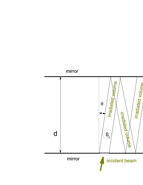
Let the laser pulse of duration enter the cavity at time , and the the value of the averaged magnetic field at entrance be . Between and the irradiated volume , as well as the number of events increase monotonously: at each a new segment is irradiated. The value of in this time interval is approximately
| (9) |
where is the speed of light and, for simplicity, we introduced the notation . After the end of the laser pulse, for , the irradiated spot propagates through the cavity but its volume remains unchanged, and after each reflection, i.e. at every , the magnetic field in the segments is suppressed by the factor , that leads to
| (10) |
From here . For large measurement times
| (11) |
Without a multi-pass cavity, the number of laser-stimulated spin-flip events at the same physical conditions would be . The “amplification effect” of the multi-pass cavity is therefore described with the factor
| (12) |
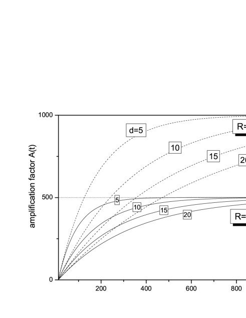
the whole dependence on being hidden in the rightmost factor. Fig. 2 is a plot of for the typical values of the parameters ns, and , and the set of values cm.
3 Optimization of the measurement time gate
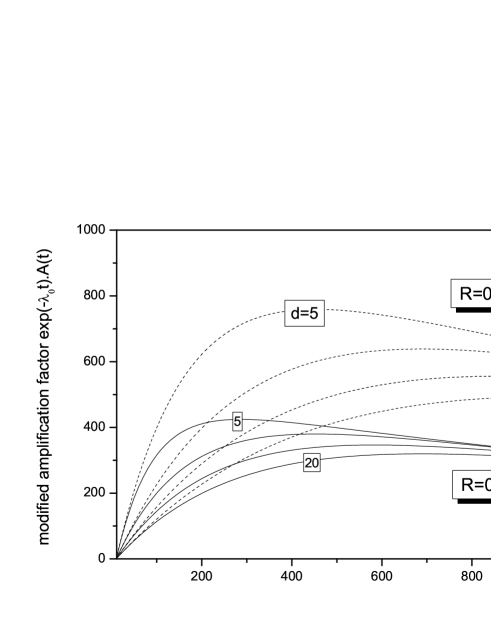
Eq. (11) gives the upper limit of the amplification factor: ; Fig. 2 shows that the time needed to reach the maximal amplification grows fast with the distance between mirrors and with the mirror reflectivity . Knowing the explicit dependence of the number of spin-flip events on the measurement time may therefore help select the optimal measurement time gate for which the number of laser-stimulated spin-flip events is maximal. In such an optimization problem one should, of course, take into account the finite muon decay rate as well. As shown of Fig. 3, the muon decay partly suppresses the gain of laser-stimulated spin-flip events due to the multi-pass cavity.
To optimize the efficiency of the FAMU experiment, however, one should maximize the signal-to-noise ratio rather than just the number of laser-stimulated spin-flip events. In the experimental method of FAMU, the “noise” (also referred to as “background”) mainly consists of characteristic X-rays emitted during the relaxation of the atoms formed through muon transfer from thermalized muonic hydrogen atoms (and therefore independent of the laser light), while the “signal” is the variation of the the background distribution due to X-rays from atoms formed by muon transfer from epithermal hfi2k ; NIMB12 . Obviously, the latter is proportional to the number of laser-stimulated events, while the “noise” depends only on the number of muonic atoms in target:
| (13) |
so that the time dependence of the signal-to-noise ratio is:
| (14) |
The noise grows monotonously with the duration of the measurement time gate while the signal reaches its maximum at some finite moment (see Fig. LABEL:ampl1). We can therefore expect to have pronounced maxima for any value of and , that will determine the optimal time gate for measurement of the hyperfine splitting of muonic hydrogen in the FAMU approach.
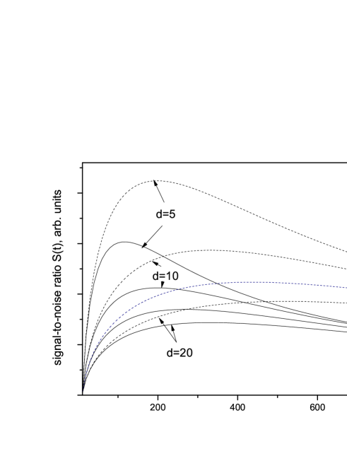
Fig. 4 confirms these qualitative predictions. We also note that:
-
•
The maximal achievable signal-to-noise ratio is increased as the distance between the mirrors decreases;
-
•
The optimal time gate length grows with inter-mirror distances ;.
4 Conclusions
The simplified model of the optical multi-pass cavity considered here completely neglects the effects of the spatial distribution of the muonic hydrogen atoms and of the laser radiation throughout the cavity, as well as some other details of the undergoing physical processes, and cannot be directly applied in simulations of the FAMU experiment. Still, it reveals important peculiarities related to the use of multi-pass cavities in experiments with pulsed laser and muon sources, and can be helpful in the preliminary design of the experimental set-up and the approximate choice of the optimal measurement time gate and inter-mirror distance.
5 Acknowledgments
The authors acknowledge the support of Grant 08-17 of the Bulgarian Science Fund.
References
- (1) https://webint.ts.infn.it/ricerca/exp/famu/
- (2) A. Adamczak, G. Baccolo, D. Bakalov, et al., JINST 11, P05007 (2016).
- (3) A. Adamczak, et al., Nucl. Instrum. Meth. B 281, 72 (2012).
- (4) E. Mocchiutti, V. Bonvicini, R. Carbone, et al., to appear in JINST (2017).
- (5) T. Matsuzaki, et al., Nucl. Instr. Meth. A 465 (2001) 365.
- (6) L.Stoychev, M. Danailov, A. Demidovich, et al., Proc. SPIE 9135, Laser Sources and Applications II, 91350J (May 1, 2014); doi:10.1117/12.2052110
- (7) A. Adamczak, D. Bakalov, K. Bakalova, E. Polacco, C. Rizzo, Hyperfine Interactions 136, 1 (2001)