A Mechanism of Failure in Shear Bands
Abstract
We have carried out dilatant plasticity simulations to investigate the process of void-mediated failure inside a shear band. The constitutive model accounts for possibly inhomogeneous flow within the band, void rotation and void elongation. We found that the material in the band may soften with no increase in the void volume fraction. For a given matrix hardening capacity, the rate of softening was found to depend strongly on the ratio of shear band width to in-plane void spacing. The emergent softening led to complete loss of load bearing capacity thereby providing a physical mechanism of failure in shear bands. The mechanism is consistent with essential features of shear-fractured specimens in terms of surface roughness, porosity and dimple shape.
Failure by shear banding is ubiquitous and occurs in complex fluids Schall and van Hecke (2010), granular materials Alshibli and Sture (2000); Gourlay and Dahle (2007), rocks Gomez-Rivas and Griera (2012) polycrystals Wei et al. (2002); Morgeneyer and Besson (2011), polymers Friedrich (1983) and metallic glasses Greer et al. (2013); Hofmann et al. (2008). However, the mechanism of material separation inside the shear band has remained elusive. Understanding it will not only potentially retard failure in shear bands, if desired, but also impact other applications where failure occurs under shear dominated loadings. The stress state in shear bands is generally complex depending on the loading path prior to the onset of strain localization Morgeneyer et al. (2016). Correspondingly, shear bands are generally dilational. While arbitrarily large tension-to-shear ratios may be encountered inside shear bands, here we focus on situations of vanishingly small tension-to-shear ratios and aim to present a physical model of complete material separation.
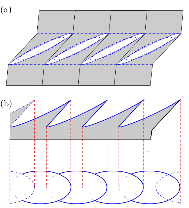
Voids are the main defects mediating ductile fracture Benzerga and Leblond (2010); Pineau et al. (2016). The plastic enlargement of these defects dominates at moderate to high ratios of tension-to-shear stress (tension-dominated loading), Fig. 1a. Voids are also believed to play an important role at low tension-to-shear ratios (shear-dominated loading), Fig. 1b. However, a specific mechanism by which failure occurs is still lacking. Void nucleation is material specific and will not be addressed here. Well-established micromechanical models of void growth and coalescence Gurson (1977); Tvergaard and Needleman (1984) predict infinite ductility under shear loading. This is due to two idealizations: (i) that the void volume fraction, , is the sole internal parameter representing the defects; and (ii) that void coalescence occurs upon attainment of a critical value of . Since the rate of growth of is completely determined by the dilational part of the macroscopic plastic strain rate, which is nil in shear, no growth is predicted, hence no failure. An attempt to remedy this consists of amending the void growth law with a shear-dependent term Nahshon and Hutchinson (2008). This proposal is attractive but presents two shortcomings. Not only does it violate the principle of mass conservation underlying the void growth law but it also presumes that a void-growth-like behavior is required for failure in shear. On the other hand, a much earlier mechanism-based model limited to isolated voids McClintock et al. (1966) did highlight the essential role of void rotation and possible linkage of neighboring voids by mere impingement. More recent direct numerical simulations Tvergaard (2008, 2009); Nielsen et al. (2012) revealed the existence of a maximum in the shear load response and exhibited three essential microscopic features: (i) void-induced strain localization at the sub-cell level; (ii) void rotation; and (iii) void elongation in the rotated state. However, such calculations are extremely challenging, and thus cannot be pursued much beyond the maximum load. Furthermore, they are not scalable so that a coarse-grained continuum model that mimics the behavior gleaned from these simulations is lacking Benzerga et al. (2016).
Quite recently, Morin et al. Morin et al. (2016) proposed mechanism-based modeling of failure under shear-dominated loadings. Their model accounts for void rotation and void shape change, but fails to account for the void-induced strain localization that occurs from the outset in shear. It also employs an ad hoc coalescence criterion, reminiscent of the critical void volume criterion used in conjunction with the Gurson model Tvergaard and Needleman (1984). In this Letter, we present a parameter-free model of failure under shear-dominated loading, which accounts for sub-cell strain localization, void rotation and void shape change, and discuss the model’s capabilities to simulate complete loss of stress carrying capacity in shear.
 |
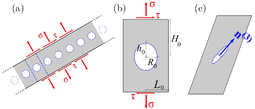
When voids are at the micron scale and above, void-mediated fracture in the shear band may be described by continuum mechanics. The shear band is assumed to be acted upon by a shear stress, , and a normal tensile stress, , Fig. 2a. Voids are assumed to have nucleated, in some way, inside the band. A regular doubly-periodic array of voids is assumed for simplicity so that analysis of a single tetragonal cell, Fig. 2b, is sufficient. The aspect ratio of the cell, , represents the current ratio of shear band thickness to in-plane void spacing. Other cell parameters include the void volume fraction, , the void aspect ratio, , along with two unit vectors: for the orientation of the void, modeled as a spheroid when it deforms, Fig. 2c, and for the orientation of the localization plane, Fig. 3. Multiple possibilities for may be chosen depending on the underlying spatial arrangement of voids. Here, only one such orientation is considered, which is normal to the shear band. Initial values of all internal parameters are indicated with subscript 0.
To investigate failure in shear, we carried out numerical simulations using a continuum micromechanics framework for dilatant plasticity that captures the essential features of sub-cell deformation sketched in Fig. 3.
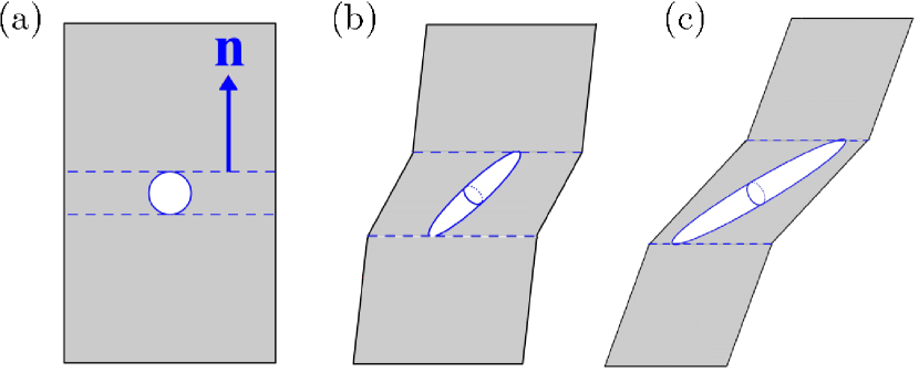
Contrary to the direct numerical simulations in Tvergaard (2008, 2009); Nielsen et al. (2012), we do not model the void explicitly, but through the coarse-grained model. The effective elasticity domain is represented by the intersection of two convex domains. Its boundary is therefore determined by the intersection of two surfaces in stress space and where yield functions and correspond to homogeneous (Fig. 2c) and inhomogeneous (Fig. 3b) deformation of the cell, respectively. The plastic portion of the symmetric part of the velocity gradient, , is obtained by normality to the effective yield surface. For generally tensile stress states , there is competition between the two yielding mechanisms Benzerga (2002); Benzerga et al. (2004) with prevailing in the early stages of any triaxial stressing process. For combined tension and shear, as in Fig. 2b, it is the ratio that determines which yielding mechanism would dominate. Yield functions derived from first principles of micromechanics are used for Keralavarma and Benzerga (2010) and Benzerga and Leblond (2014); Torki et al. (2015). Evolution equations for the internal parameters in were derived in Keralavarma and Benzerga (2010); also see Kweon et al. (2016) for computational details. For sufficiently low (shear-dominated loading) inhomogeneous yielding dominates from the outset so that all subsequent deformation history is governed by . Details about the two-surface formulation may be found as Supplemental Material. Here, it suffices to exhibit the governing equations for inhomogeneous yielding:
| (1) |
with
| (2) |
| (3) |
where the effective ligament parameter, , and effective void aspect ratio, , correspond to an equivalent cylindrical void with axis , obtained by a volume-preserving projection of the rotating spheroidal void onto the localization plane. The exact shape, spheroidal versus cylindrical, has little incidence on yielding Morin et al. (2015). However, since equations (1) were derived for cylindrical voids Torki et al. (2015), this choice is made here (see Supplemental Material). Also, is the flow stress in shear of the material without voids, taken as a power law in the effective plastic strain with the initial yield strength, Young’s modulus, and the hardening exponent. Implicit dependence upon the void axis in (1) is through and dependence upon the localization plane normal is through , as well as and with a unit vector along the applied shear.
Upon continued plastic loading, the structure evolves according to (with , and ):
| (4) |
| (5) |
| (6) |
| (7) |
| (8) |
| (9) |
| (10) |
Eqn. (4) expresses plastic incompressibility of the matrix Gurson (1977) and Eqns. (5) and (6) are for the constrained motion of the top and bottom void boundaries due to elastic unloading above and below the void (see Supplemental Material for derivations.) Also, in (4) is the plastic multiplier, , in (6) represents the deviation from the continuum spin due to the eigen-rotation of the void, calculated using Eshelby concentration tensors Eshelby (1957) after Kailasam and Ponte Castaneda (1998); Kweon et al. (2016), is the shear-induced rotation that comes from mere distortion of void boundaries (dominant here), and is the deformation gradient used to update the band orientation . Relations (5)–(8) are straightfroward generalizations of the evolution equations of Benzerga Benzerga (2002) in the absence of shear, whereas (9) is taken from Leblond and Mottet (2008). The effective plastic strain is evolved using Gurson’s identity:
| (11) |
The above plastic relations were augmented with hypoelasticity within an objective co-rotational finite deformation framework. The nonlinear constitutive relations were integrated using an implicit time integration scheme similar to Kweon et al. (2016).
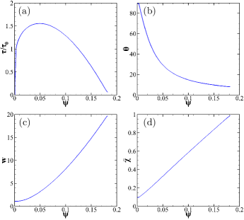
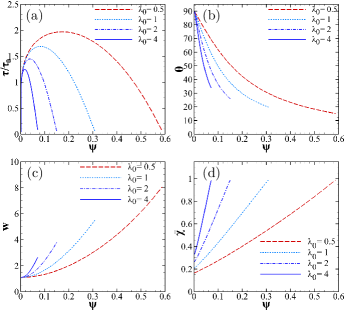
The typical shear stress versus shear angle response, Fig. 4a, results from competing effects of matrix hardening (set by ) and microstructural softening induced by void rotation, Fig. 4b, and elongation in the rotated state, Fig. 4c. The angle is such that . As a result, the area of the void projected onto the plane of localization increases monotonically, as captured through the effective ligament parameter, , Fig. 4d. When approaches unity all stress carrying capacity vanishes by virtue of (1). This occurs while the void volume fraction remains constant (not shown). In actuality, some decrease in is expected. To capture this detail would require a three-dimensional void model Morin et al. (2016) and would have little effect on essential behavior (see Supplemental Material for further details).
 |
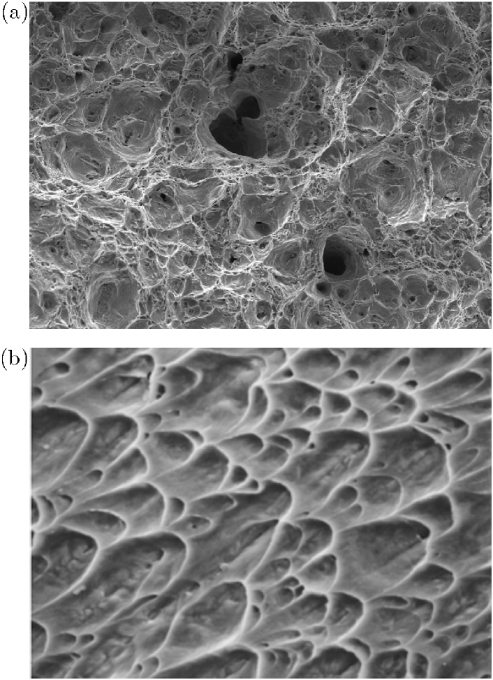
To link the above findings with salient features of sheared fracture surfaces, Fig. 1b, consider few neighboring cells at about the ultimate state (dashed in Fig. 5a). We assume that final linkup would occur by some finer-scale microshear process, Fig. 5b. In reality, void distributions are not periodic so that it is likely that when the elongated void reaches the lateral boundaries, it will link up with a neighboring void. Details aside, a top view of the so-simulated fracture surface, Fig. 5c, provides a rationale for three key experimental observations: (i) parabolic dimples; (ii) low surface roughness; and (iii) low local porosity, relative to tensile fracture surfaces, Fig. 1a. Both roughness and porosity are related to the dimple height, which is set by the amount of rotation prior to failure. In the example shown (Fig. 4b) the rotation is actually much more than depicted in Fig. 5.
 |
At fixed hardening capacity of the matrix material and fixed void volume fraction , the strain to failure is dependent upon the ratio of initial band thickness to in-plane void spacing, Fig. 6a. The rotation of the void, Fig. 6b, and its aspect ratio (Fig. 6c) are also sensitive to . For fixed porosity of initially spherical voids (), varying amounts to varying (Fig. 6d), which has a direct effect on the strain to failure.
 |
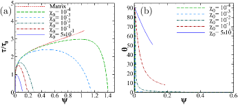
To investigate this effect further, the initial ligament parameter was varied over four decades. The results in Fig. 7 show that the strain to failure is essentially set by the value of , which represents the size of voids that nucleate inside the shear band, relative to their in-plane spacing. In case of the dense matrix (no voids), the response becomes homogeneous as expected, Fig. 7a. However, even in the dilute case failure is predicted so long as there are voids. Of course, there is a lower limit in a continuum description on the void size implied by a given choice of . What is essential is that the lower the value of the more localized the plastic flow inside the shear band, and this leads to a faster rotation of the voids, as illustrated in Fig. 7b. This result suggests that materials in which small voids are able to nucleate inside the shear band, such as metallic glasses Shao et al. (2014), would have a lower fracture surface roughness. This is due to the vanishingly small dimple height, as the voids would have almost completely rotated.
Our results illustrate for the first time a possible mechanism of failure inside shear bands. They also show that a micromechanical dilatant plasticity framework can provide new insights into aspects of material behavior heretofore not explained using either continuum or atomistic approaches. The predictions connect macroscopic behavior with detailed microscopic information about observables (the voids) and measurable attributes thereof. Once the model is implemented to solve boundary-value problems, further contact with experiments can be made.
We gratefully acknowledge financial support from the National Science Foundation under grant CMMI-1405226.
References
- Schall and van Hecke (2010) P. Schall and M. van Hecke, Annual Review of Fluid Mechanics 42, 67 (2010).
- Alshibli and Sture (2000) K. A. Alshibli and S. Sture, J. Geotech. Geoenviron. Eng. 126, 495 (2000).
- Gourlay and Dahle (2007) C. M. Gourlay and A. K. Dahle, Nature 445, 70 (2007).
- Gomez-Rivas and Griera (2012) E. Gomez-Rivas and A. Griera, J. Struct. Geol. 34, 61 (2012).
- Wei et al. (2002) Q. Wei, D. Jia, K. T. Ramesh, and E. Ma, Appl. Phys. Lett. 81, 1240 (2002).
- Morgeneyer and Besson (2011) T. F. Morgeneyer and J. Besson, Scr. Mater. 65, 1002 (2011).
- Friedrich (1983) K. Friedrich, Adv. Pol. Sci. 52-3, 225 (1983).
- Greer et al. (2013) A. L. Greer, Y. Q. Cheng, and E. Ma, Mater. Sci. Eng.:R 74, 71 (2013).
- Hofmann et al. (2008) D. C. Hofmann, J.-Y. Suh, A. Wiest, G. Duan, M.-L. Lind, M. D. Demetriou, and W. L. Johnson, Nature 451, 1085 (2008).
- Morgeneyer et al. (2016) T. F. Morgeneyer, T. Taillandier-Thomas, A. Buljac, L. Helfen, and F. Hild, J. Mech. Phys. Solids 96, 550 (2016).
- Benzerga and Leblond (2010) A. A. Benzerga and J.-B. Leblond, Adv. Appl. Mech. 44, 169 (2010).
- Pineau et al. (2016) A. Pineau, A. A. Benzerga, and T. Pardoen, Acta Mater. 107, 424 (2016).
- Gurson (1977) A. L. Gurson, J. Eng. Mat. Tech. 99, 2 (1977).
- Tvergaard and Needleman (1984) V. Tvergaard and A. Needleman, Acta Metall. 32, 157 (1984).
- Nahshon and Hutchinson (2008) K. Nahshon and J. W. Hutchinson, Eur. J. Mech. A 27, 1 (2008).
- McClintock et al. (1966) F. A. McClintock, S. M. Kaplan, and C. A. Berg, Int. J. Frac. Mech. 2, 614 (1966).
- Tvergaard (2008) V. Tvergaard, Int. J. Mech. Sci. 50, 1459 (2008).
- Tvergaard (2009) V. Tvergaard, Int. J. Frac. 158, 41 (2009).
- Nielsen et al. (2012) K. L. Nielsen, J. Dahl, and V. Tvergaard, Int. J. Frac. 177, 97 (2012).
- Benzerga et al. (2016) A. A. Benzerga, J.-B. Leblond, A. Needleman, and V. Tvergaard, Int. J. Frac. 201, 29 (2016).
- Morin et al. (2016) L. Morin, J. Leblond, and V. Tvergaard, J. Mech. Phys. Solids 94, 148 (2016).
- Benzerga (2002) A. A. Benzerga, J. Mech. Phys. Solids 50, 1331 (2002).
- Benzerga et al. (2004) A. A. Benzerga, J. Besson, and A. Pineau, Acta Mater. 52, 4639 (2004).
- Keralavarma and Benzerga (2010) S. M. Keralavarma and A. A. Benzerga, J. Mech. Phys. Solids 58, 874 (2010).
- Benzerga and Leblond (2014) A. A. Benzerga and J.-B. Leblond, J. Appl. Mech. 81, 031009 (2014).
- Torki et al. (2015) M. E. Torki, A. A. Benzerga, and J.-B. Leblond, J. Appl. Mech. 82, 071005 (2015).
- Kweon et al. (2016) S. Kweon, B. Sagsoy, and A. A. Benzerga, Comput. Methods Appl. Mech. Eng. 310, 495 (2016).
- Morin et al. (2015) L. Morin, J.-B. Leblond, and A. A. Benzerga, J. Mech. Phys. Solids 75, 140 (2015).
- Eshelby (1957) J. Eshelby, Proc. Roy. Soc A241, 357 (1957).
- Kailasam and Ponte Castaneda (1998) M. Kailasam and P. Ponte Castaneda, J. Mech. Phys. Solids 46, 427 (1998).
- Leblond and Mottet (2008) J.-B. Leblond and G. Mottet, C. R. Mecanique 336, 176 (2008).
- Shao et al. (2014) Y. Shao, G.-N. Yang, K.-F. Yao, and X. Liu, Appl. Phys. Lett. 105, 181909 (2014).