Simultaneous coherence enhancement of optical and microwave transitions in solid-state electronic spins
Abstract
Solid-state electronic spins are extensively studied in quantum information science, as their large magnetic moments offer fast operations for computing Wesenberg et al. (2009) and communication Togan et al. (2010); Gao et al. (2013); Bussières et al. (2014), and high sensitivity for sensing Grinolds et al. (2014). However, electronic spins are more sensitive to magnetic noise, but engineering of their spectroscopic properties, e.g. using clock transitions and isotopic engineering, can yield remarkable spin coherence times, as for electronic spins in GaAs Bluhm et al. (2011), donors in silicon George et al. (2010); Tyryshkin et al. (2011); Wolfowicz et al. (2013); Lo et al. (2015); Morse et al. (2017) and vacancy centres in diamond Balasubramanian et al. (2009); Sukachev et al. (2017). Here we demonstrate simultaneously induced clock transitions for both microwave and optical domains in an isotopically purified 171Yb3+:Y2SiO5 crystal, reaching coherence times of above 100 µs and 1 ms in the optical and microwave domain, respectively. This effect is due to the highly anisotropic hyperfine interaction, which makes each electronic-nuclear state an entangled Bell state. Our results underline the potential of 171Yb3+:Y2SiO5 for quantum processing applications relying on both optical and spin manipulation, such as optical quantum memories Bussières et al. (2014); Saglamyurek et al. (2015), microwave-to-optical quantum transducers Probst et al. (2013); Fernandez-Gonzalvo et al. (2015), and single spin detection Bienfait et al. (2016), while they should also be observable in a range of different materials with anisotropic hyperfine interaction.
A very effective method for increasing spin coherence times consists in engineering a particular spin transition so that its frequency is insensitive to magnetic fluctuations, i.e. up to first order. Such transitions are known as clock transitions in atomic physics, and were pioneered for nuclear spin systems in solid-state materials Fraval et al. (2004) where they are called ZEFOZ (ZEro First Order Zeeman) transitions. The ZEFOZ technique is based on the application of a magnetic bias field in a particular ”magic” direction, where simultaneously for all three spatial coordinates. The existence of such a direction depends entirely on the spin Hamiltonian of the system. Recently ZEFOZ transitions were also observed for electronic spins in silicon Wolfowicz et al. (2013); Morse et al. (2017), showing its general appeal for spin coherence enhancement.
In rare-earth (RE) ion doped crystals, engineered ZEFOZ transitions have been very effective in extending nuclear spin coherence times, by orders of magnitude, for REs without electronic spin () Fraval et al. (2004); Lovrić et al. (2011); Zhong et al. (2015). However, ZEFOZ transitions have not yet been achieved in RE ions having both electronic and nuclear spin degrees of freedom, so-called Kramers RE ions (containing odd number of electrons) Bertaina et al. (2007); Wolfowicz et al. (2015); Rančić et al. (2017). These often have shorter coherence lifetimes due to the large electronic spin coupling to the spin bath of the crystal, which is composed of nuclear spins and the RE spins themselves, unless large magnetic fields are applied Rančić et al. (2017). In terms of optical coherence times, RE ions are unique solid state centres as optical coherences can reach milliseconds Thiel et al. (2011). In short this is due to the shielding of the 4 electrons due the 5, 5 orbitals, which reduces the coupling to phonons in RE materials. But also in the optical domain one needs to apply large magnetic fields to reach long optical coherence times for Kramers ions Sun et al. (2002). Yet, electronic spins are highly promising for broadband optical quantum memories Bussières et al. (2014); Saglamyurek et al. (2015), microwave-to-optical quantum transduction and coupling to superconducting qubits Probst et al. (2013); Fernandez-Gonzalvo et al. (2015). There is thus a general interest in simultaneously enhancing the spin and optical coherence times of Kramers ions, in order to profit from their distinct advantages. In addition, to interface with superconducting resonators and qubits, ZEFOZ transitions under low or zero magnetic fields are of particular interest.
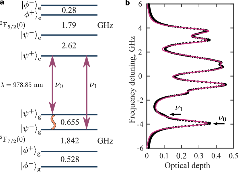
In this study we use 171Yb3+, a Kramers ion that recently has received interest for quantum information processing owing to its simple hyperfine structure. Basic optical Böttger et al. (2016); Welinski et al. (2016); Tiranov et al. (2017) and spin Welinski et al. (2016); Tiranov et al. (2017) properties have been studied, and recent electron spin resonance measurements have shown promising spin coherence times at high magnetic fields (73 µs at around 1 T Lim et al. (2018)). The 171Yb3+ is indeed unique among RE Kramers ions, as it has the lowest possible, non-zero, electronic and nuclear spin, resulting in the simplest possible hyperfine manifold of four states, as shown in Figure 1a. This fact greatly simplifies both the optical and spin spectra and makes optical manipulation of the hyperfine levels possible, an important feature of this work.
In this system, the electronic spin of the ytterbium ion is coupled with its nuclear spin through the hyperfine interaction tensor , and the effective spin Hamiltonian involving the interaction with an external magnetic field can be written as
| (1) |
Here, and are coupling tensors related to the electronic and nuclear Zeeman interactions of 171Yb3+, respectively, and and are the electronic and nuclear magnetons. In the Y2SiO5 crystal the 171Yb3+ ions replace Y3+ ions in sites of low () point symmetry, which makes the hyperfine and Zeeman tensors highly anisotropic for both the ground and excited states Welinski et al. (2016). In general, for a highly anisotropic tensor (with non-zero eigenvalues )), the hyperfine coupling completely removes the degeneracy at zero magnetic field. It gives rise to the four eigenstates and , where we decompose electronic , and nuclear , spin components. Their energies are expressed as and .
By tracing out the electronic (nuclear) spin one can easily see that the resulting density matrix corresponds to the complete mixture of two orthogonal components (), which is true for any eigenstate. This inherently gives a zero total spin vector for the electronic (nuclear ) spin polarization. Hence any first-order perturbation of the energy levels by the Zeeman terms of Eq. (1) is strictly zero for both the electronic and nuclear Zeeman components. More explicitly, for any state the following is true: for any perturbing magnetic field . These results apply to any electronic state, hence the zero-field ZEFOZ condition occurs for any spin transition in the ground and excited states, and for any optical transition connecting the two electronic states. A similar effect has been observed in the hyperfine ground state in NV centres in diamond Dolde et al. (2011); Jamonneau et al. (2016), but only for a reduced number of states due to the higher symmetry of the interaction tensor and particularly not for any optical transition.
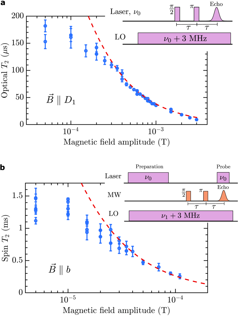
To probe the zero-field spin and optical coherences in 171Yb3+:Y2SiO5 we use the transitions and , the latter being clearly resolved in the absorption spectrum in Figure 1b. By means of optical pumping on the optical transition, the population difference between two spin states is created. A Hahn sequence on the spin transition follows, inducing an echo pulse in the microwave range, which is optically detected using Raman heterodyne scattering Fraval et al. (2004) (see Methods for details). The coherence lifetime is thus measured as a function of the external magnetic field applied in various directions. The optical coherence lifetime is instead measured through a standard photon echo technique using the same optical absorption line (Figure 1b).
Figure 2b shows measurement results for the lifetime as the magnetic field is varied close to the expected zero-field ZEFOZ point along the crystal axis. The coherence increases as the magnetic field is lowered, exceeding lifetime for few tens of T. A similar behaviour is observed for the optical coherence , which approaches close to zero field (Figure 2a). These results clearly demonstrate the effectiveness of the zero-field ZEFOZ point for decoupling the 171Yb spins from the perturbing spin bath. Remarkably these spin and optical coherence times are similar to those found in non-Kramers RE ions (with ) at zero field Thiel et al. (2011).
The decoherence due to a given magnetic field noise can be modelled as Zhong et al. (2015) , where and are the linear (gradient) and quadratic (curvature) Zeeman contributions to a transition energy. In a ZEFOZ point the linear term ideally vanishes and the limitation comes from the quadratic term. Here we use the known hyperfine Tiranov et al. (2017) and Zeeman Welinski et al. (2016) tensors to calculate and , and fit the noise term for fields away from the ZEFOZ point, using both spin and optical data (see Figure 2a and b). This results in , consistent with previous measurements in Y2SiO5 and is due to spin flip-flops of yttrium ions in this crystal Lovrić et al. (2011); Zhong et al. (2015). At zero field, however, the model predicts up to spin coherence time. The lower experimental value (maximum 4 ms was measured) could possibly be attributed to the presence of a bias magnetic field, which a separate measurement estimated to be .
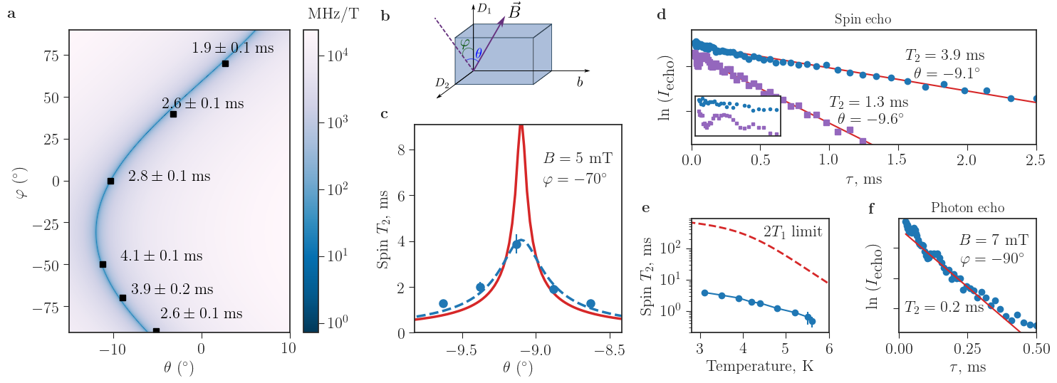
We also explore a second ZEFOZ-like regime, using the low-field assisted coherence enhancement technique, as shown on Figure 3. It is based on the fact that the direction of an extremely small magnetic bias field can strongly reduce the linear term . This is due to the high anisotropy of the tensor for the ground state which has the strongest component close to the axis of the crystal Welinski et al. (2016), while its perpendicular components are up to fifty times lower and vary between and . In addition, the tensor is almost parallel to the tensor and the two have a similar anisotropy Tiranov et al. (2017). For a bias small field applied in the direction, the gradient is . For 171Yb3+:Y2SiO5 this results in for bias fields of a few mT along the axis (see Methods for details). In fact, any field in the - plane results in a strongly reduced gradient, of the order of a nuclear spin sensitivity.
Figure 3a shows the numerically calculated gradient for a range of orientations of the bias field . We here work in the (, , ) crystal frame commonly used in optics Welinski et al. (2016), in which the - plane is slightly tilted. The calculated gradient varies over four orders of magnitude in the narrow range shown in Figure 3a, with minimum gradients lower than 10 MHz/Tesla close to the - plane. Such gradients are typical of nuclear spins, while electronic spins have gradients of 10 GHz/T or more. The calculations also indicate that a high precision of the bias field alignment is required to reach the minimum region of gradients, as explained below.
Although magnetic sensitivities of the energy levels are on the order of nuclear moment, the dipole moments of the addressed transitions remain as high as for electronic ones. Explicitly, with and being a constant arising from the elements of the electronic tensor in the direction. By aligning along the strongest component of the tensor we achieve Rabi frequencies of around 1 MHz for a weak excitation field of around 30 T (see Methods for details).
An example of a spin coherence lifetime measurement taken with a small scan of at is shown in Figure 3c, together with the theoretical model using the calculated gradient and a magnetic noise of . The peak coherence time is 4 ms, and less than a degree misalignment significantly reduces the coherence time. This confirms that even extremely small bias fields can have a strong effect on the coherence properties in electronic spin systems characterized by a strongly anisotropic tensor. Measurements made at different angles displayed the same behaviour, and the maximum coherence lifetimes are shown at their corresponding angular coordinates in Figure 3a. In the entire plane of minimum gradients we achieve coherence times above 1 ms for a bias field of 5 mT.
The main limitation in the achieved spin coherence times using the bias field method probably stems from the inhomogeneity of the applied field. As seen in Figure 3c, the field has to be precise to within 1/10 of a degree to reach the theoretical maximum. Our numerical calculations show that field inhomogeneities of in one cm3 volume are enough to explain the experimental data (Figure 3c). Ohter possible limitations are discussed below.
Optical coherence times of up to 200 s were also measured with magnetic fields applied in the same directions where spin coherence times are maximum. An example of a photon echo decay measurement is shown in Figure 3f. The angular dependence was much less pronounced as with respect to the spin coherence measurement, a few degrees misalignment did not significantly reduce the coherence time. Probably, this is due to the dependence of the optical gradient on the tensors in both the ground and excited states, which are not completely aligned Welinski et al. (2016). Generally this helps one to simultaneously reach long optical and spin coherence times.
Another possible limitation to the achieved coherence times, both in the zero and low field regimes, comes from the superhyperfine interaction taking place between the electronic Yb3+ spin and nuclear spins of the environment. In the Y2SiO5 host nearest-neighbour nuclear spins of 89Y (100% with ) and 29Si (5% with ) interacts strongly with Yb3+, and we expect this interaction to modify the transition gradients. Further analysis is required in order to estimate these contributions to the observed spin coherence times. In addition, these interactions cause splitting of the microwave transitions when a magnetic bias field is applied, which causes characteristic oscillations on the spin echo decays curves. Such oscillations were seen at short time scales in the measurements with a small bias field, as shown in Figure 3d. The period of the oscillations is consistent with coupling to 89Y ions. Surprisingly, these oscillations were systematically quenched in amplitude as the field was tuned to the optimal angle. Although this effect is not yet fully understood, this is an useful feature of these optimal points for applications such as quantum memories.
Finally, we studied the spin coherence lifetime as a function of temperature, with a magnetic field applied in the optimum point for . As shown in Figure 3e, the coherence time remains above 100 s for temperatures up to 5.6 K. Also, it remains well below the limit given by the spin-lattice relaxation lifetime as measured in Ref. [(29)]. However, cross-relaxation between 171Yb3+ ions are likely to reduce the lifetime of the hyperfine states Cruzeiro et al. (2017), in addition to causing spectral diffusion Thiel et al. (2011). Further studies should measure and quantify these contributions to the measured spin coherence lifetimes, for instance by varying the 171Yb3+ doping concentration and/or applying a magnetic field gradient as shown with naturally doped silicon samples Tyryshkin et al. (2011).
The spin coherence times we measured are similar to those found in naturally doped silicon, where the nuclear spin of 29Si causes magnetic noise. In silicon, coherence times of 10 seconds have been reached by isotope purification (pure 28Si samples) Tyryshkin et al. (2011). In contrary, yttrium has the unique isotope 89Y which has a nuclear spin, making such an approach impossible for Y2SiO5. A possible solution is to use an isotopically enriched versions of tungsten oxide crystals (for example CaWO4), whose naturally doped version was studied with various rare-earth dopants in the past Bertaina et al. (2007); Rakhmatullin et al. (2009).
The described coherence enhancement techniques can generally be applied to any system having anisotropic Zeeman and hyperfine interaction. Particularly, they can be extended to higher odd nuclear spins (, , ) coupled with half electronic spin () (see Methods for details). Our approach in this case is directly applicable to other isotopes of Kramers ions with non-zero nuclear spin, in particular to 167Er3+ which is of high interest for quantum communication owing to its optical transition in the telecommunications band Rančić et al. (2017). Recent experiments Rakonjac et al. (2018) in 167Er3+ have reached promising hyperfine coherence times (up to 300 µs) by also using the mixing of electronic and nuclear spins at zero magnetic field, but without fully exploiting a ZEFOZ point. Hence, with ZEFOZ points or the low-field assisted enhancement techniques used in our work, the spin coherence time could potentially be increased further. Other systems of interest include single molecular electron magnets incorporating rare earth ions Zadrozny et al. (2015); Shiddiq et al. (2016).
In conclusion, we have shown that simultaneous enhancement of both optical and spin coherence times is possible, by using induced clock transitions at zero field or by minimizing the transition gradients using extremely low magnetic bias fields. These techniques are applicable to any electronic spin system having anisotropic Zeeman and hyperfine interactions. The 171Yb3+:Y2SiO5 material studied here features a set of unique properties, such as a simple hyperfine manifold, optically resolved optical-hyperfine transitions and long coherence times, making it a great resource for quantum information applications. This system will be highly interesting for applications in broadband optical quantum memories Bussières et al. (2014); Saglamyurek et al. (2015) and coupling to superconducting resonators/qubits in the microwave regime Probst et al. (2013); Bienfait et al. (2016).
Methods
Crystal
Our sample is a 171Yb3+:Y2SiO5 crystal with ppm doping concentration and with an Yb3+ isotope purity of , grown via Czochralski method and cut along the , and extinction axes. The sides parallel to these axes are long respectively , and , and the faces parallel to the plane were polished so to reduce the scattering of the input light. Another crystal grown from the same bulk but with dimensions , and respectively was polished along the faces and used only for coherence lifetime measurements on site I (see ”Opically detected spin echo” section). Y2SiO5 has a monoclinic structure of the space group. Yb3+ can replace Y3+ ions in two different crystallographic sites of point symmetry (referred to as site I and II), which in turn include two magnetically inequivalent sub-sites each. All results presented in the main text were obtained from site II. The hyperfine transitions of the two magnetic sites coincided when no static magnetic field was applied, but they could be addressed separately when we introduced few in directions not orthogonal nor parallel to . The optical transitions had a Full Width Half Maximum of , while for the hyperfine transitions the FWHM was about .
Experimental setup
The crystal was placed in a cryostat at about . A small coil of copper wire, connected to a generator and a amplifier, surrounded the crystal along the axis and allowed us to address the microwave transitions by inducing ac magnetic fields. The inductance of the coil was estimated to be 0.2 µH, which gives % of input microwave power to be transmitted to the crystal for 655 MHz excitation frequency. The induced ac magnetic field amplitude in this case could go up to µT.
A larger superconducting coil was placed along either or axes, and was used to create a component of the external static magnetic field up to . Placed out of the cryostat along the remaining crystal axes, two pairs of copper coils in a Helmholtz configuration completed the static field generation setup, with a maximum of few each. This solution proved to be enough for generating the required field along the directions of maximal suppression of decoherence presented in the main text. A external cavity diode laser generated the optical beams, which were manipulated in amplitude and frequency by acousto-optical modulators so to precisely define the pulse sequences we needed. The laser was split in two main paths, namely the pump/probe sent on the crystal and a local oscillator used in the heterodyne detection scheme. A non-linear crystal-based phase modulator controlled the frequency of the local oscillator.
Optically detected spin echo
We measure the spin coherence lifetime through optical detection of a spin echo in a Hahn sequence using the Raman heterodyne scattering (RHS) technique Fraval et al. (2004); Lovrić et al. (2011); Zhong et al. (2015). All spin echo measurements reported in this paper were carried out on the transition () of optical site II. We also obtained similar results () for the transition () for a small scan of magnetic field along in the range . When addressing these two transitions, the excitation coil needed to be oriented with its main axis along , in agreement with our model (see main text). The linear polarization of the input light was aligned to be parallel to , so to maximize the absorption. Our predictions were also confirmed by measurements on site I at and respectively. Similarly to site II, values of above were found, with a field orientation along at . Spectral hole lifetimes above for temperatures below assured us that the coherence was not limited by the population lifetime.
The ensemble was first prepared by optical pumping at frequency in with few . The duration of the pulse in our echo sequence was of and a Rabi frequency up to was measured by driving the spin transition at and probing at the same time the transmitted intensity of light on the detector. The signal generated on the detector was analysed with a Fast Fourier Transform and the area of the peak corresponding to the beat at was acquired at various time delays . The coherence lifetime was then extracted by fitting the peak area decays as .
The maxima of coherence lifetimes at non-zero magnetic field were found by optimizing the intensity of the echo at increasingly long delays and correcting accordingly the magnetic field orientation. Similarly, we looked for the highest intensity of the echo when compensating the bias field of the lab while applying small intensities of external field.
The error bars are obtained as follows: the amplitude and width of the echo signal are extracted from a Gaussian fit with 95% confidence intervals. The corresponding residuals are propagated to find the error on the area of the echo. The latter is in turn propagated on the natural logarithm of the area. For each value of magnetic field, the logarithm of the areas are fitted as a linear function of to find . The error on corresponds to a 95% confidence interval on this last linear fit.
Photon echo
The optical coherence lifetime is measured in an analogous way by preparing a photon echo sequence on a transition between a ground and an excited state. In this case, no preparation of population is needed, since the excited state is empty at the temperature considered, and the echo is readily detectable from the photodiode without RHS. However, we chose to measure an RHS signal at since, in our case, the technique leads to increased sensitivity to the echo amplitude. The duration of the pulse was about . The errors on the coherence lifetimes are obtained as explained in the spin echo section.
Generalization of zero–field ZEFOZ for higher nuclear spins
We find that the ZEFOZ behavior is generic for all transitions at zero magnetic field under the following sufficient conditions:
-
1.
The hyperfine coupling is fully anisotropic (i.e., all three eigenvalues of the coupling tensor A are different and nonzero) to avoid degeneracies in the Hamiltonian;
-
2.
The electronic spin is and the nuclear spin is half integer.
This situation leads to a symmetry in the hyperfine coupling and maximally entangled eigenstates. The latter implies a vanishing polarization of the electronic spin and hence a vanishing first order sensitivity to external magnetic fields. Also the polarization of the nuclear spin vanishes due to this symmetry. The ZEFOZ behavior in general disappears when the symmetry is broken, that is, when eigenvalues degenerate, when the nuclear spin is an integer or when the electronic spin is not .
Let us consider the situation with higher nuclear spin , coupled with electronic spin one half. The hyperfine interaction alone leads to eigenstates of the form , where , are coefficients defined by the eigenvalues of the tensor. The average electronic polarization is zero since the wavefunction can be rewritten as , where the weights for and components are the same and . The nuclear polarization appears to be zero as well, since the projections with the opposite signs appear to have same probabilities giving . Vanishing and are also found for higher half-integer nuclear spins (, , etc.).
For the full description one has to consider the quadrupolar tensor which also contributes to the zero-field splittings. However, the quadrupole interaction does not disturb the symmetry of the wavefunction for half-integer . Hence, the ZEFOZ condition persists even in the presence of the quadrupole interaction. In contrast, if and are not aligned and is an integer, the quadrupolar term seems to make the eigenstates even more susceptible to fluctuations in the plane (in the eigenbasis of ).
Low magnetic field assisted coherence enhancement
In presence of a relatively small magnetic field (few millitesla) it is still possible to find an orientation which preserves the coherence. In Tiranov et al. (2017), it was found that the and tensors are highly anisotropic ( together with ) with their strongest component along very close directions. The following calculations can thus be simplified by assuming that the two tensors diagonalize in the same basis, while keeping the direction as the one along which their components are strongest. Using Eq. (1), we can see how the transition sensitivities change with an external static magnetic field with (, , ) components by computing the magnitude of the gradient for one of the transitions:
| (2) |
Considering and , the presence of the product on the numerator of the first term and in the denominator of the other terms tells us that to minimize the transition gradient it is convenient to choose a magnetic field orthogonal to the axis. The expression above can thus be simplified:
| (3) |
where is the angle on the plane orthogonal to . Minimizing this expression leads us to a non-zero minimum of the gradient, similarly to a ZEFOZ, with a consequent suppression of decoherence.
Data availability
The data sets generated and/or analysed during the current study are available from the corresponding authors upon reasonable request.
ACKNOWLEDGEMENTS
We acknowledge funding from the Swiss FNS NCCR programme Quantum Science Technology (QSIT) and FNS Research Project No 172590, EUs H2020 programme under the Marie Skłodowska-Curie project QCALL (GA 675662), EU’s FP7 programme under the ERC AdG project MEC (GA 339198), ANR under grant agreement no. 145-CE26-0037-01 (DISCRYS) and Nano’K project RECTUS and the IMTO Cancer AVIESAN (Cancer Plan, C16027HS, MALT).
Competing interests
The authors declare no competing interests.
References
- Wesenberg et al. (2009) J. H. Wesenberg, A. Ardavan, G. A. D. Briggs, J. J. L. Morton, R. J. Schoelkopf, D. I. Schuster, and K. Mølmer, Phys. Rev. Lett. 103, 070502 (2009).
- Togan et al. (2010) E. Togan, Y. Chu, A. S. Trifonov, L. Jiang, J. Maze, L. Childress, M. V. G. Dutt, A. S. Sørensen, P. R. Hemmer, A. S. Zibrov, and M. D. Lukin, Nature 466, 730 (2010).
- Gao et al. (2013) W.-B. Gao, P. Fallahi, E. Togan, A. Delteil, Y. S. Chin, J. Miguel-Sanchez, and A. Imamoğlu, Nature Communications 4, 2744 (2013).
- Bussières et al. (2014) F. Bussières, C. Clausen, A. Tiranov, B. Korzh, V. B. Verma, S. W. Nam, F. Marsili, A. Ferrier, P. Goldner, H. Herrmann, C. Silberhorn, W. Sohler, M. Afzelius, and N. Gisin, Nat. Photon. 8, 775 (2014).
- Grinolds et al. (2014) M. S. Grinolds, M. Warner, K. De Greve, Y. Dovzhenko, L. Thiel, R. L. Walsworth, S. Hong, P. Maletinsky, and A. Yacoby, Nature Nanotechnology 9, 279 (2014).
- Bluhm et al. (2011) H. Bluhm, S. Foletti, I. Neder, M. Rudner, D. Mahalu, V. Umansky, and A. Yacoby, Nat Phys 7, 109 (2011).
- George et al. (2010) R. E. George, W. Witzel, H. Riemann, N. V. Abrosimov, N. Nötzel, M. L. W. Thewalt, and J. J. L. Morton, Phys. Rev. Lett. 105, 067601 (2010).
- Tyryshkin et al. (2011) A. M. Tyryshkin, S. Tojo, J. J. L. Morton, H. Riemann, N. V. Abrosimov, P. Becker, H.-J. Pohl, T. Schenkel, M. L. W. Thewalt, K. M. Itoh, and S. A. Lyon, Nature Materials 11, 143 (2011).
- Wolfowicz et al. (2013) G. Wolfowicz, A. M. Tyryshkin, R. E. George, H. Riemann, N. V. Abrosimov, P. Becker, H.-J. Pohl, M. L. W. Thewalt, S. A. Lyon, and J. J. L. Morton, Nature Nanotechnology 8, 561 (2013).
- Lo et al. (2015) C. C. Lo, M. Urdampilleta, P. Ross, M. F. Gonzalez-Zalba, J. Mansir, S. A. Lyon, M. L. W. Thewalt, and J. J. L. Morton, Nature Materials 14, 490 (2015).
- Morse et al. (2017) K. J. Morse, R. J. S. Abraham, A. DeAbreu, C. Bowness, T. S. Richards, H. Riemann, N. V. Abrosimov, P. Becker, H.-J. Pohl, M. L. W. Thewalt, and S. Simmons, Science Advances 3, 7 (2017).
- Balasubramanian et al. (2009) G. Balasubramanian, P. Neumann, D. Twitchen, M. Markham, R. Kolesov, N. Mizuochi, J. Isoya, J. Achard, J. Beck, J. Tissler, V. Jacques, P. R. Hemmer, F. Jelezko, and J. Wrachtrup, Nature Materials 8, 383 (2009).
- Sukachev et al. (2017) D. D. Sukachev, A. Sipahigil, C. T. Nguyen, M. K. Bhaskar, R. E. Evans, F. Jelezko, and M. D. Lukin, Phys. Rev. Lett. 119, 223602 (2017).
- Saglamyurek et al. (2015) E. Saglamyurek, J. Jin, V. B. Verma, M. D. Shaw, F. Marsili, S. W. Nam, D. Oblak, and W. Tittel, Nat. Photon. 9, 83 (2015).
- Probst et al. (2013) S. Probst, H. Rotzinger, S. Wünsch, P. Jung, M. Jerger, M. Siegel, A. V. Ustinov, and P. A. Bushev, Phys. Rev. Lett. 110, 157001 (2013).
- Fernandez-Gonzalvo et al. (2015) X. Fernandez-Gonzalvo, Y.-H. Chen, C. Yin, S. Rogge, and J. J. Longdell, Phys. Rev. A 92, 062313 (2015).
- Bienfait et al. (2016) A. Bienfait, J. J. Pla, Y. Kubo, M. Stern, X. Zhou, C. Lo, C. Weis, T. Schenkel, M. Thewalt, D. Vion, D. Esteve, B. Julsgaard, K. Mølmer, J. J. L. Morton, and P. Bertet, Nature Nanotechnology 11, 253 (2016).
- Fraval et al. (2004) E. Fraval, M. J. Sellars, and J. J. Longdell, Phys. Rev. Lett. 92, 077601 (2004).
- Lovrić et al. (2011) M. Lovrić, P. Glasenapp, D. Suter, B. Tumino, A. Ferrier, P. Goldner, M. Sabooni, L. Rippe, and S. Kröll, Phys. Rev. B 84, 104417 (2011).
- Zhong et al. (2015) M. Zhong, M. P. Hedges, R. L. Ahlefeldt, J. G. Bartholomew, S. E. Beavan, S. M. Wittig, J. J. Longdell, and M. J. Sellars, Nature 517, 177 (2015).
- Bertaina et al. (2007) S. Bertaina, S. Gambarelli, A. Tkachuk, I. N. Kurkin, B. Malkin, A. Stepanov, and B. Barbara, Nature Nanotechnology 2, 39 (2007).
- Wolfowicz et al. (2015) G. Wolfowicz, H. Maier-Flaig, R. Marino, A. Ferrier, H. Vezin, J. J. L. Morton, and P. Goldner, Phys. Rev. Lett. 114, 170503 (2015).
- Rančić et al. (2017) M. Rančić, M. P. Hedges, R. L. Ahlefeldt, and M. J. Sellars, Nature Physics (2017), 10.1038/NPHYS4254.
- Thiel et al. (2011) C. Thiel, T. Böttger, and R. Cone, Journal of Luminescence 131, 353 (2011).
- Sun et al. (2002) Y. Sun, C. W. Thiel, R. L. Cone, R. W. Equall, and R. L. Hutcheson, J. Lumin. 98, 281 (2002).
- Böttger et al. (2016) T. Böttger, C. W. Thiel, R. L. Cone, Y. Sun, and A. Faraon, Phys. Rev. B 94, 045134 (2016).
- Welinski et al. (2016) S. Welinski, A. Ferrier, M. Afzelius, and P. Goldner, Phys. Rev. B 94, 155116 (2016).
- Tiranov et al. (2017) A. Tiranov, A. Ortu, S. Welinski, A. Ferrier, P. Goldner, N. Gisin, and M. Afzelius, arXiv: 1712.08616 (2017).
- Lim et al. (2018) H.-J. Lim, S. Welinski, A. Ferrier, P. Goldner, and J. J. L. Morton, Phys. Rev. B 97, 064409 (2018).
- Dolde et al. (2011) F. Dolde, H. Fedder, M. W. Doherty, T. Nobauer, F. Rempp, G. Balasubramanian, T. Wolf, F. Reinhard, L. C. L. Hollenberg, F. Jelezko, and J. Wrachtrup, Nat Phys 7, 459 (2011).
- Jamonneau et al. (2016) P. Jamonneau, M. Lesik, J. P. Tetienne, I. Alvizu, L. Mayer, A. Dréau, S. Kosen, J.-F. Roch, S. Pezzagna, J. Meijer, T. Teraji, Y. Kubo, P. Bertet, J. R. Maze, and V. Jacques, Phys. Rev. B 93, 024305 (2016).
- Cruzeiro et al. (2017) E. Z. Cruzeiro, A. Tiranov, I. Usmani, C. Laplane, J. Lavoie, A. Ferrier, P. Goldner, N. Gisin, and M. Afzelius, Phys. Rev. B 95, 205119 (2017).
- Rakhmatullin et al. (2009) R. M. Rakhmatullin, I. N. Kurkin, G. V. Mamin, S. B. Orlinskii, M. R. Gafurov, E. I. Baibekov, B. Z. Malkin, S. Gambarelli, S. Bertaina, and B. Barbara, Phys. Rev. B 79, 172408 (2009).
- Rakonjac et al. (2018) J. V. Rakonjac, Y.-H. Chen, S. P. Horvath, and J. J. Longdell, arXiv: 1802.03862 (2018).
- Zadrozny et al. (2015) J. M. Zadrozny, J. Niklas, O. G. Poluektov, and D. E. Freedman, ACS Central Science 1, 488 (2015).
- Shiddiq et al. (2016) M. Shiddiq, D. Komijani, Y. Duan, A. Gaita-Ariño, E. Coronado, and S. Hill, Nature 531, 348 (2016).
See pages 1 of Yb_zefoz_supplement
See pages 2 of Yb_zefoz_supplement