PLANET-DRIVEN SPIRAL ARMS IN PROTOPLANETARY DISKS: II. IMPLICATIONS
Abstract
We examine whether various characteristics of planet-driven spiral arms can be used to constrain the masses of unseen planets and their positions within their disks. By carrying out two-dimensional hydrodynamic simulations varying planet mass and disk gas temperature, we find that a larger number of spiral arms form with a smaller planet mass and a lower disk temperature. A planet excites two or more spiral arms interior to its orbit for a range of disk temperature characterized by the disk aspect ratio , whereas exterior to a planet’s orbit multiple spiral arms can form only in cold disks with . Constraining the planet mass with the pitch angle of spiral arms requires accurate disk temperature measurements that might be challenging even with ALMA. However, the property that the pitch angle of planet-driven spiral arms decreases away from the planet can be a powerful diagnostic to determine whether the planet is located interior or exterior to the observed spirals. The arm-to-arm separations increase as a function of planet mass, consistent with previous studies; however, the exact slope depends on disk temperature as well as the radial location where the arm-to-arm separations are measured. We apply these diagnostics to the spiral arms seen in MWC 758 and Elias 2–27. As shown in Bae et al. (2017), planet-driven spiral arms can create concentric rings and gaps, which can produce more dominant observable signature than spiral arms under certain circumstances. We discuss the observability of planet-driven spiral arms versus rings and gaps.
1 INTRODUCTION
Recent observations with state-of-the-art telescopes have imaged multi-armed spirals in protoplanetary disks (e.g., MWC 758, Grady et al. 2013, Benisty et al. 2015, Reggiani et al. 2017; SAO 206462, Muto et al. 2012, Garufi et al. 2013, Stolker et al. 2016, Maire et al. 2017; Elias 2–27, Pérez et al. 2016; AB Aur, Tang et al. 2017). While the origin of the observed spiral arms is not clearly understood, one compelling possibility is gravitational interaction between a (proto)planet and the underlying disk. If the observed spiral arms are indeed launched by a planetary companion, they can provide a unique opportunity to gain crucial insights into their formation and coevolution with their host disks.
While there have been many recent efforts to explain the observed spiral arms with planetary companions, different numerical simulations do not always agree. For example, it is debatable whether a potential planet has to be located interior or exterior to the observed spiral arms. Also, the number of planets needed to explain the observed spiral arms is not clear: if we detect two spiral arms, is one planet enough to explain both arms, or do we need a second planet?
In the companion paper (Bae & Zhu 2017, hereafter Paper I), we described the mechanism by which a planet excites multiple spiral arms in the underlying protoplanetary disk. Building on this understanding, in the present paper we carry out a suite of two-dimensional hydrodynamic simulations and investigate how characteristics of planet-driven spiral arms, such as the number of spiral arms, pitch angle of spiral arms, arm-to-arm separation, and the relative strength of spiral arms, vary as a function of disk temperature and planet mass. The main aim of the parameter study is to examine whether such characteristics of observed spiral arms can be used to constrain the mass and/or position of yet unseen planet.
The observability of planet-driven spiral arms is determined mainly by their openness and the magnitude of the perturbations they produce: the more opened a spiral arm is and the larger perturbation a spiral arm produces, it will be more readily observable. Based on three-dimensional hydrodynamic calculations and radiative transfer simulations, Dong & Fung (2017) suggested that at least a Saturn-mass planet is required to excite detectable spiral arms with current observational capabilities. Spiral arms driven by smaller-mass planets may not be directly detectable. However, they still can create observable signatures: concentric rings and gaps. In Bae et al. (2017) we showed that each spiral arm launched by a planet can create its own gap through shock dissipation. This means that when a planet excites multiple spiral arms, it can create multiple gaps in the disk. Pressure maxima (i.e., rings) can develop between those gaps, potentially trapping solid particles. Preferentially in disks with a low viscosity, it is possible that low-mass planets not capable of generating observable spiral arms can still induce sufficient trapping of solid particles that can be observable (Bae et al., 2017, see also Section 5.2 of the present paper). The generation of multiple rings and gaps by planet-driven spiral arms might also have implications for terrestrial body assembly in the solar nebula, as discussed later.
This paper is organized as follows. In Section 2, we briefly summarize the formation mechanism of planet-driven spiral arms discussed in detail in Paper I. In Section 3, using a suite of two-dimensional hydrodynamic simulations with various planet mass and disk temperature, we examine whether characteristics of observed spiral arms can be used to constrain the mass and/or position of an unseen planet. In Section 4, we apply the diagnostics to the spiral arms observed in the disks around MWC 758 and Elias 2–27, and discuss their potential origin(s). In Section 5, we discuss when spiral arms would be more readily observable than rings and gaps, and vice versa, and discuss the potential role of pressure bumps created by Jupiter’s core in the solar nebula. We summarize our findings in Section 6.
2 PLANET-DRIVEN SPIRAL ARM FORMATION MECHANISM
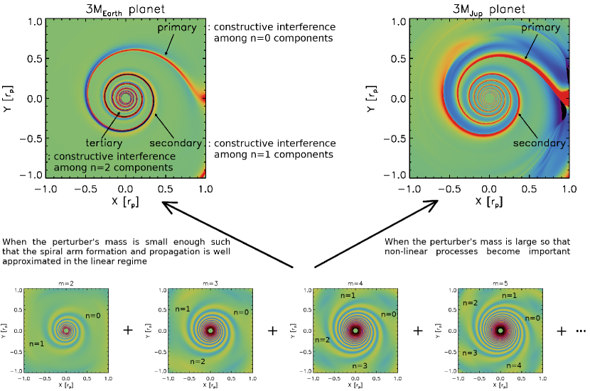
The gravitational potential of a planet can be decomposed into a Fourier series, a sum of individual azimuthal modes having azimuthal wavenumbers . Through the resonance between the rotation of the planet’s potential and the epicyclic motion of disk material, the th Fourier component of the potential launches wave modes at its Lindblad resonances (Goldreich & Tremaine, 1978a, b, 1979, see also the review by Shu 2016). In the lower panels of Figure 1 we present as examples the spiral wave patterns excited by individual azimuthal modes with and 5.
When the mass of a planet is small enough so that non-linear effects can be safely ignored, we can simply add up the perturbations driven by individual azimuthal modes to reconstruct the perturbation driven by the full potential of the planet. The upper left panel of Figure 1 shows the resulting density perturbation in the disk. In this example three spiral arms are launched interior to the planet’s orbit: the primary arm forms right at the vicinity of the planet, whereas additional arms, denoted as secondary and tertiary, start to appear at a distance (in radius) from the planet. In the Fourier representation, it is , , and components from individual azimuthal modes having different that generate the primary, secondary, and tertiary arms. As can be seen in the lower panels of Figure 1, non-zero th components excite out of phase initially; however, the propagation of wave modes depend on the azimuthal wavenumber in a way that they can be in phase as they propagate. Exterior to the planet’s orbit, the components generate the primary arm and the components generate the secondary arm.
As the planet mass increases, non-linear effects become increasingly important. One of the main outcomes is that spiral arms become more opened, because spiral arms from a larger mass planet produce stronger shocks so propagate at faster speeds. Varying planet mass can thus have influence on the pitch angle of spiral arms, arm-to-arm separation, but also the total number of spiral arms excited by a planet, as can be inferred from the upper right panel of Figure 1.
2.1 A Generalized Analytic Formula for the Phases of Spiral Arms
An important feature in the planet-driven spiral arm formation mechanism is that the formation of both primary and additional arms can be understood as a linear process when the planet mass is sufficiently small. We can thus make use of linear wave theory to predict phases of spiral arms. Here we provide a generalized analytic formula that can be used to fit observed spiral arms or to mimic spiral arms in models without carrying out planet-disk interaction simulations.
For low-mass planets (e.g., gap-opening mass), the following phase equation provides the phases of both primary and additional arms as a function of radius:
| (1) | |||||
Here, is the radius of the planet’s circular orbit, is the outer (with plus sign) and inner (with minus sign) Lindblad resonances, is the azimuthal wavenumber, represents individual wave modes, is the disk rotational frequency, is the sound speed, and is the radius of the planet’s circular orbit. As we showed in Paper I, phases of spiral arms follow the dominating azimuthal mode with well in the linear regime, where is the disk aspect ratio at planet’s orbit. The primary arm phase can be calculated with and . As can be inferred from Equation (1), one can simply shift the primary arm phase by in azimuth for additional arms, where and 2 for the secondary and the tertiary arms in the inner disk and for the secondary arm in the outer disk. The derivation of Equation (1) can be found in Section 2 of Paper I.
3 WHICH CHARACTERISTICS OF OBSERVED SPIRAL ARMS CAN WE USE?
The two main factors that determine the characteristics of spiral arms are the planet mass and the disk temperature. If we can measure disk midplane temperature accurately, we may thus be able to use some characteristics of observed spiral arms to constrain the mass of unseen planet. In order to examine which characteristics of spiral arms can be used, we carry out a suite of two-dimensional isothermal hydrodynamic simulations varying planet mass and disk temperature.
We solve the hydrodynamic equations for mass and momentum conservation in the two-dimensional polar coordinates using FARGO 3D (Benítez-Llambay & Masset, 2016): The simulation domain extends from to in radius and from 0 to in azimuth. We adopt 4096 logarithmically-spaced grid cells in the radial direction and 5580 uniformly-spaced grid cells in the azimuthal directions.
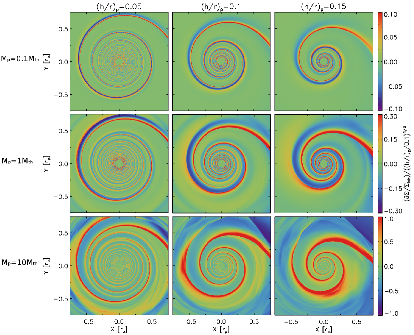
Our initial disk has a power-law surface density and temperature profile: and , where and are the surface density and temperature at the location of the planet . We use planet masses of , and , where is the so-called thermal mass (Lin & Papaloizou, 1993; Goodman & Rafikov, 2001), at which planet mass its Hill radius is comparable to the disk scale height. We choose such that the disk aspect ratio at the location of the planet is , and 0.15. For = 0.04 and 0.05, we also run calculations with and .
In Figure 2, we display the perturbed surface density distributions with some selected parameters to provide an overview. As expected, characteristics of spiral arms, such as the number of spiral arms, the pitch angle of spiral arms, and the arm-to-arm separation vary as a function of planet mass and disk temperature.
3.1 Can We Use the Number of Observed Spiral Arms?
Additional spiral arms form when wave modes having different azimuthal wavenumbers become in phase as they propagate. The propagation of wave modes depends on their azimuthal wavenumber but also the background disk temperature. For a given azimuthal wavenumber, a wave mode in a colder disk is more tightly wound and narrower in width. This raises the possibility that a larger number of additional arms can form. In addition, as we showed in Paper I the mass of the planet also affects the number of spiral arms.
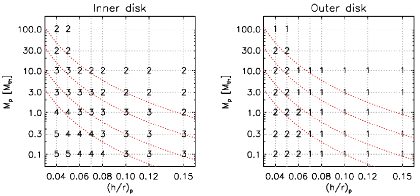
In Figure 3, we present the number of spiral arms launched by planets in the inner () and outer disk () as a function of and . Planets launch two or more (up to five in our parameter space) spiral arms interior to their orbits. At a given disk temperature, a smaller number of spiral arms form with a larger planet mass. Also, in general, a smaller number of spiral arms form in a disk with a larger . As mentioned at the beginning of this section, this trend is expected because having a larger planet mass and/or a larger will make spiral arms (or wave modes) more opened, prevent more spiral arms forming. Our parameter study shows that, for , three or fewer spiral arms form interior to a planet’s orbit when and two-armed spirals form when . These masses correspond to a Saturn mass and 3 Jupiter masses, respectively, assuming a solar-mass central star.
Exterior to their orbits, we find that planets launch only one or two spiral arms. The number of outer spiral arms appears to be more sensitive to the disk temperature than the planet mass. Fewer spiral arms form in the outer disk than in the inner disk because propagation of wave modes become independent on the azimuthal wavenumber when (see Equation 1). Therefore, additional spiral arms can form only when non-zero th components become in phase within , which can occur in cold disks. Our parameter study shows that two spiral arms form exterior to a planet’s orbit only when .
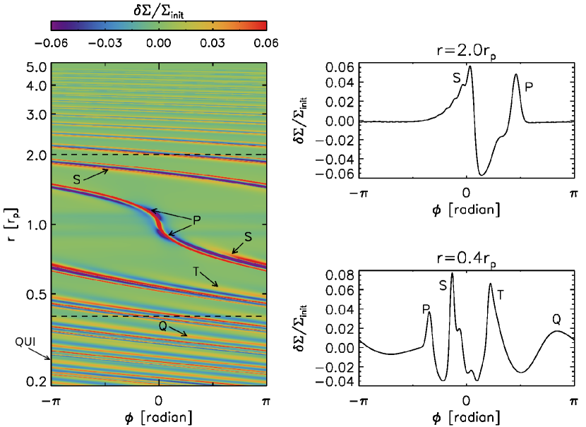
In Figure 4, we present an example of which the largest number of spiral arms in our parameter study are launched: five in the inner disk and two in the outer disk. The parameters used in the example are and . In addition to the primary arm directly attached to the planet, interior to the planet’s orbit a secondary arm forms at , a tertiary arm forms at , a quaternary arm forms at , and a quinary arm forms at . Exterior to the planet’s orbit, a secondary arm forms at and no more spiral arms form beyond this radius. With a small planet mass of (=6.4 Earth mass assuming a solar mass star), the level of perturbation driven by the spiral arms is low (). These spiral arms are therefore unlikely to be detectable in near-IR scattered light images (Dong & Fung, 2017). While weak, however, these spiral arms may still be able to generate observable signatures preferentially in low-viscosity disks by opening gaps as they shock the disk gas, provided that sufficient time is allowed (Bae et al. 2017; see also Section 5 of the present paper).
3.2 Can We Use the Pitch Angle of Spiral Arms?
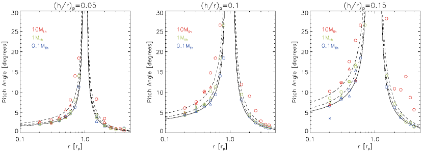
In Figure 5, we present measured pitch angles of spiral arms from our simulations. The pitch angles are measured using as we follow each spiral arm in radius. In general, for any given disk temperature, larger planet masses result in larger pitch angles. So in theory we can use the pitch angle to constrain the mass of unseen planet. In practice, however, there are difficulties. First of all, we note that highly accurate temperature measurements are required. As shown in Figure 5 even a uncertainty in temperature can change the mass estimates by an order of magnitude. Given the difficulty of measuring the actual midplane gas temperature, arising for instance from relating mm continuum emissions to gas temperatures or from using molecular line ratios which tend not to probe exactly the same disk regions in height, making an one-to-one correlation between the pitch angle of a spiral arm to the planet mass seems challenging, at least for now. Even when the disk midplane temperature is accurately measured, an additional uncertainty in the mass constraints comes from the fact that we do not know the location of the planet and thus the exact value. Many of the spiral arms observed so far have fluctuating pitch angles (e.g., Reggiani et al., 2017), another challenge to use the pitch angle to constrain planet mass.
On the other hand, as shown in Figure 5 the pitch angles of both primary and additional spiral arms decrease away from the planet. This is expected from linear wave theory and numerical simulations show the trend as well. It is a particularly important characteristic because, if we measure the pitch angle of a spiral arm over a large enough radial range, the increasing or decreasing trend of the pitch angle can be used to distinguish whether the spiral arm is excited by a planet inside or outside of the spirals (see Section 4.1).
3.3 Can We Use the Arm-to-Arm Separation?
Previous numerical simulations showed that the separation between the primary and secondary arm increases with the planet mass (Zhu et al., 2015; Fung & Dong, 2015; Lee, 2016). Interestingly, a parameter study presented in Fung & Dong (2015) showed that the arm-to-arm separation is independent of the disk temperature profile. It is thus suggested that the arm-to-arm separation can be broadly used to infer the mass of unseen planet.
We compute arm-to-arm separations from our simulations. Specifically, we measure the angular separation between spiral arms at each radius. We then average it around , 0.3, 0.4, 0.5, and for the primary-to-secondary separation and around , 0.2, and for the secondary-to-tertiary separation, with a radial bin of . Focusing on models first, we present the primary-to-secondary separation and the secondary-to-tertiary separation as a function of the planet mass in Figure 6. For both and , there is a general trend that the arm-to-arm separation increases with the planet mass, consistent with previous studies (Zhu et al., 2015; Fung & Dong, 2015). For , it converges to beyond for which planet mass only two spiral arms form. For the planet masses in a range of (), the primary-to-secondary arm separation at is best fitted with . However, we note that the arm-to-arm separation increases more steeply with the planet mass at smaller radii. The best-fit slopes for individual radial bins increase from 0.11 at to 0.22 at . Similarly, the slope in also increases more steeply at smaller radii. It is therefore helpful to know an approximate planet location for more accurate mass estimates with arm-to-arm separation.
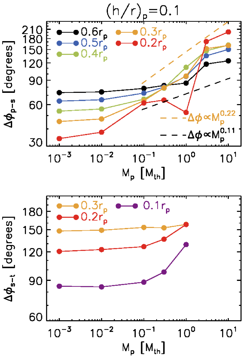
There are a few other things worth pointing out from Figure 6. First, compared at a given radius, is larger than regardless of the planet mass. Second, both and flatten out for sufficiently low mass planets, suggesting that spiral arms cannot be infinitely close to each other in the linear regime. Last, for a given planet mass, increases as a function of radius for low-mass planets (i.e., ) while the separation decreases as a function of radius for high-mass planets (i.e., ).
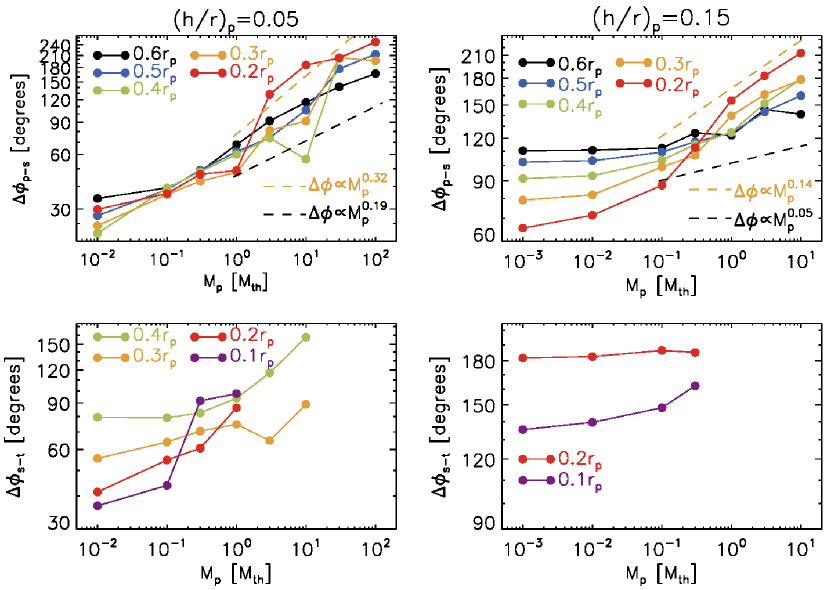
In Figure 7, we present and measured in simulations with and . Comparing Figure 7 with Figure 6, we note that the general trends seen in the fiducial case with are commonly seen with and 0.15. Most importantly, the arm-to-arm separation increases more steeply with the planet mass at smaller radii with other values. It is worth noting that this trend is more clearly seen with larger values because the interference and/or merging between spiral arms tends to occur more frequently with smaller values.
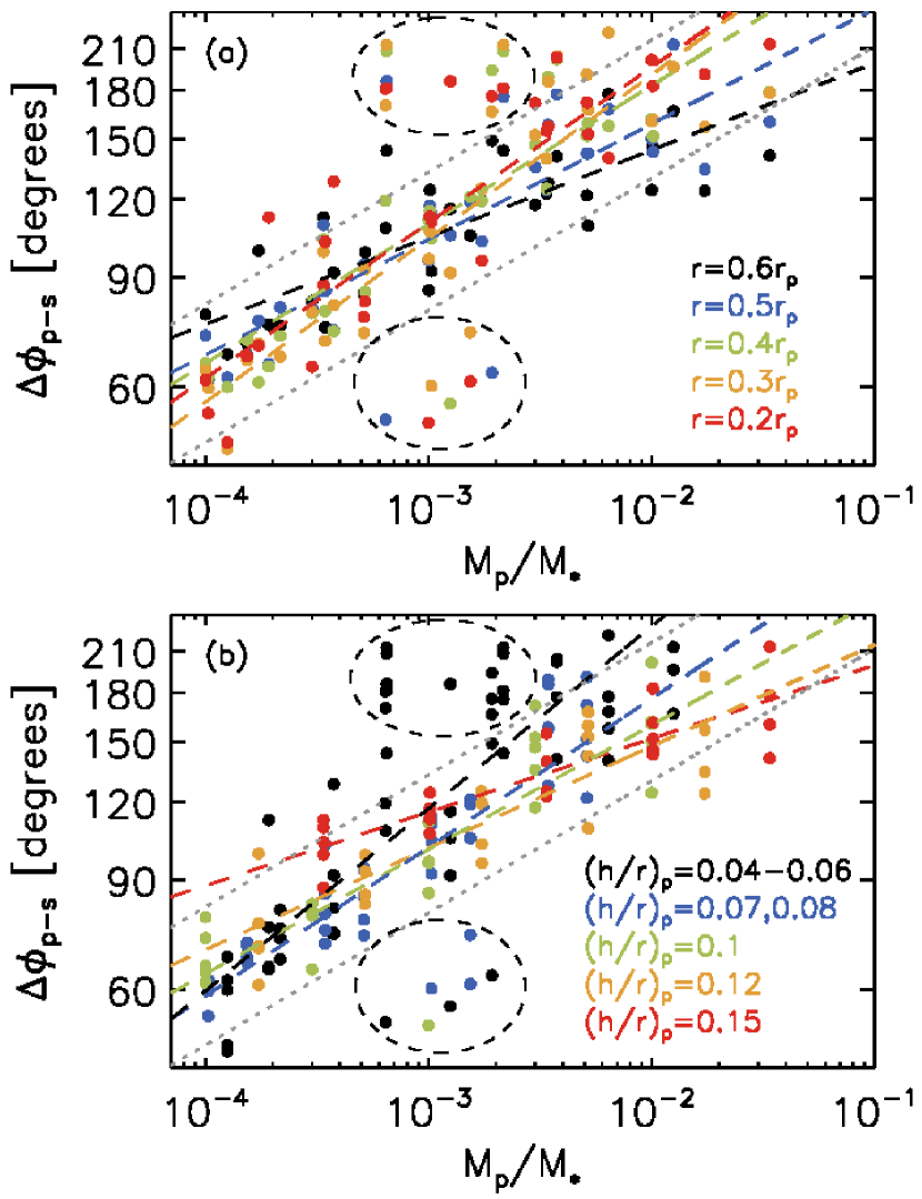
In Figure 8 (a), we present computed in all our models differing and . Data points are color-coded to represent at different radial bins. Note that the axis of the plot is now planet-to-star mass ratio , different from Figure 6 and 7. We fit the data points having , chosen similarly to Fung & Dong (2015) for a comparison. The entire data points are best fitted with where , which is in an excellent agreement with Fung & Dong (2015). However, as in Figure 6 and 7, we find there is a general trend that the arm-to-arm separations increase more steeply at smaller radii. In Figure 8 (b), data points are now color-coded to represent different in models. Again, we do find a trend that the arm-to-arm separation increases more steeply with smaller values. In Table 2, we provide the best fits to relation. A fit given for a certain radius uses the data points with all values, whereas a fit given for a certain value uses the data points at all different radii. In the appendix, we provide best fits for each values and radial bins.
To summarize, we confirm that the arm-to-arm separation increases with the planet mass, in agreement with previous studies (Zhu et al., 2015; Fung & Dong, 2015; Lee, 2016). Our best-fit of primary-to-secondary separation is . However, we find that, in the inner disk, the arm-to-arm separation increases more steeply with the planet mass at smaller radii and with smaller values.
| Data | Best Fits |
|---|---|
| entire data points | |
3.4 Can We Use the Relative Brightness/Intensity of Spiral Arms?
First of all, secondary and tertiary arms can create stronger density perturbations/contrast than the primary arm at a given radius (e.g., Figure 4; see also Fung & Dong 2015). In addition, the brightness/intensity of spiral arms can significantly differ from their intrinsic brightness/intensity because of interaction with background disk structures (e.g., a vortex; Bae et al. 2016a) and/or distortion via the spiral wave instability (Bae et al., 2016b). In case of near-IR scattered light observations, shadows cast by structures located closer to the central star may also affect the brightness of spiral arms located far away (Stolker et al., 2016). We thus caution that observed intensity or brightness of spiral arms is not an ideal characteristic to determine whether a certain spiral arm is a primary or a secondary/tertiary but also to provide planet mass constraints. Variations in the brightness of spiral arms seen in multi-epoch scattered light observations (e.g., Stolker et al., 2016, 2017) also support this conclusion.
4 Application to the Observed Spiral Arms
4.1 MWC 758
MWC 758 is a Myr-old Herbig Ae star (Meeus et al., 2012) at a distance of pc (Gaia Collaboration et al., 2016). Two spiral arms are detected in near-IR scattered light observations using the Subaru Telescope High Contrast Instrument with Adaptive Optics in Ks- and H-band (Grady et al., 2013) and the VLT with Spectro-Polarimetric High-contrast Exoplanet Research in Y-band (Benisty et al., 2015). Recently, using L’-band observations with NIRC2 at the Keck II telescope, Reggiani et al. (2017) reported three spiral arms (two previously reported + one new) spanning in between 0.”25 and 0.”6 ( au) from the central star. In addition, a point-like source is detected at a separation of 0.”11 (20 au) from the central star (Reggiani et al., 2017), making the disk a very interesting object to test planet-disk interaction theories.
To examine a potential planetary origin of the spiral arms in the MWC 758 disk, we first assume an external companion at 100 au and at the radius, similarly to the model in Dong et al. (2015) but rescaled with the distance based on Gaia Collaboration et al. (2016). Assuming that the external companion is responsible for all three spiral arms, our parameter study suggests that the unseen planet should have a mass less than 3 thermal mass; a larger-mass planet would excite only two spiral arms. Adopting a 1.5 solar mass central star (Isella et al., 2010; Reggiani et al., 2017) gives an upper limit of 7.8 Jupiter mass. An interesting feature regarding the arm-to-arm separation is that the separation between the arm S1 and S3 decreases with radius (see Figure 7 of Reggiani et al. 2017). Although a radially decreasing arm-to-arm separation is not completely unexpected as Figure 6 shows (see and for example), such a small arm-to-arm separation of as well as a rapid drop over a short radial distance is not what is typically seen our simulations – assuming again a companion at 100 au as above, the arm-to-arm separation decreases from at to at . One possibility to explain these features might be interference between the arms (Paper I), but our understanding of the phenomenon is too incomplete to arrive at a conclusion.
We note that the point-like source detected in Reggiani et al. (2017) is unlikely to be the perturber exciting three spiral arms exterior to its orbit based on our parameter study. However, it is possible that the point-like source excites one of the three spiral arms and a yet unseen external companion excites the other two. In fact, we find some supporting features that S3 could be an outer spiral of a planet interior to S3. First, the decreasing pitch angle of S3 as a function of radius (Figure 5 of Reggiani et al. 2017) supports the idea that S3 is an outer spiral arm launched by an internal perturber (see Section 3.2). This also helps resolve the arm-to-arm separation problems discussed in the previous paragraph. In addition, it is known from three-dimensional simulations that inner spiral arms produce significant vertical motion while the outer spiral arms induce little vertical motion (Zhu et al., 2015). If S3 is an outer spiral arm it is likely that the pressure scale height along the arm does not increase significantly. This can explain the non-detection of S3 at a shorter wavelength in Y-band (m; Benisty et al. 2015) which trace upper layers of the disk than L’-band. This scenario is consistent with a suggestion made in Reggiani et al. (2017) and also supports the suggestion by Juhász et al. (2015) that observed spiral arms might be the results of pressure scale height changes. While no apparent physical connection between the point-like source and S3 is found from the scattered light image, it is possibly because the point-like emission traces a protoplanet located near the midplane whereas S3 traces the surface. This explanation is consistent with the inclination and PA of the disk. In the case an unseen external planet excites two of the three spiral arms, the external companion has to be more massive than a thermal mass (see Section 3.1). We are thus left with a fairly narrow companion mass range of Jupiter mass: the lower limit from our parameter study and the upper limit from Reggiani et al. (2017).
When the three spiral arms do not share the same origin, distinguishable orbital motions among the spirals are expected in monitoring observations. If spiral arm S3 is excited by the point-like source at 20 au, the spiral pattern will rotate per year in the deprojected plane. Assuming an external planet at au is responsible for the other two spiral arms, the two spirals will rotate per year in the deprojected plane. Therefore, observations in 2018 may reveal more than of difference in the orbital motions between spiral arm S3 and the other two compared with the first epoch observation of Reggiani et al. (2017) taken in 2015 October.
4.2 Elias 2-27
Elias 2-27 is a young ( Myr; Luhman & Rieke 1999), low-mass (0.6 solar-mass; Andrews et al. 2009) star in the -Ophiuchus star-forming region. This object is particularly interesting because spiral arms are detected at mm wavelengths with ALMA (Pérez et al., 2016). The emission at 1.3 mm is optically thin, so the continuum emission traces down to the midplane of the disk (Pérez et al., 2016), in contrast to near-IR scattered light imaging which trace spiral arms near the disk surface.
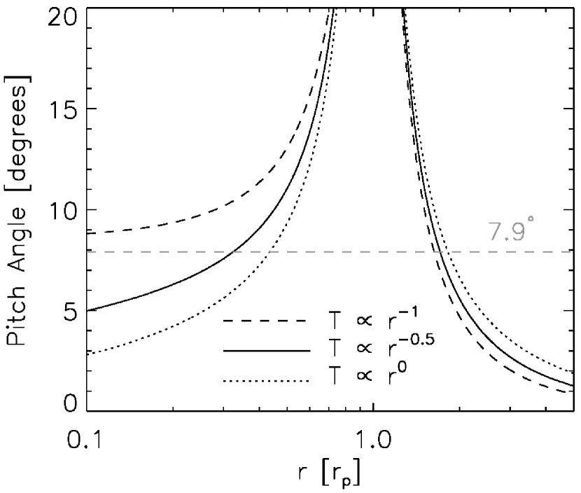
Both spiral arms in the Elias 2-27 disk appear to be well fit with two symmetric logarithmic spirals, i.e., a constant pitch angle of (Pérez et al., 2016). This is an interesting characteristic because a constant pitch angle is unlikely for planet-driven spiral arms (Figure 5; see also Zhu et al. 2015). One possibility is that the disk has a steeper temperature gradient than the constraints made in Pérez et al. (2016). In Figure 9 we plot the predicted pitch angles as a function of radius based on the linear wave theory, assuming . As shown, the steeper the disk temperature gradient is, the more slowly the pitch angle varies in the inner disk. If it is the temperature gradient alone though, the planet probably has to be located at very large distance ( au) to help its inner spiral arms have a constant pitch angle. More accurate temperature measurements in the future could help test whether this is the case. If the two spiral arms are driven by a planet exterior to the spirals, our parameter study suggests that the planet has to be more massive than about a Jupiter mass assuming the midplane temperature constrained by Pérez et al. (2016). This planetary mass is consistent with constraints made by previous observations and numerical simulations (see Meru et al. 2017 and references therein). The disk has beyond au, so it is very unlikely that an internal planet excites the two spiral arms.
Alternatively, it might be that a constant pitch angle is a generic characteristic of GI-driven spiral arms. In fact, the GI-driven spiral arms seen in numerical simulations of Bae et al. (2014) have a constant pitch angle over a broad range of radius, in particular inward of the gravitationally unstable region111The GI-driven two-armed spiral arms in Figure 14 of Bae et al. (2014) are well fitted with logarithmic spirals having a pitch angle of over au.. If the shear rate of the disk rotation is what determines the pitch angle of GI-driven spiral arms, the potential universality of a constant pitch angle among GI-driven spiral arms might be explained. Pérez et al. (2016) calculated the Toomre parameter based on the dust continuum emission and suggested that the disk can be gravitationally unstable at the radii where the spiral arms are detected, when the dust opacity is reduced by a factor of than what is typically assumed in literature. More accurate observational constraints on the gas surface density as well as improvements in our understanding of GI-driven spiral arms are desired to better understand the origin of the spiral arms in the Elias 2–27 disk.
5 Spiral Arms as an Origin of Concentric Rings and Gaps
It has been suggested that planet-driven spiral arms can create multiple concentric rings and gaps as they shock disk gas at different radial locations in a disk (Bae et al., 2017). While we have considered the appearance of planet-driven spiral arms in previous sections, in certain circumstances rings and gaps can have more dominant observable signature than spiral arms themselves. In this section, we discuss when we expect to observe rings and gaps rather than spiral arms, and vice versa. We then discuss the generation of multiple rings and gaps in the solar nebula by a proto-Jupiter and its potential implications.
5.1 Spiral arms vs. rings and gaps
In order for spiral arms to be observable, they have to (1) have a large enough pitch angle to overcome a finite spatial resolution (see e.g., Figure 4 of Kanagawa et al. 2015); and (2) produce a sufficient level of perturbations (Dong & Fung, 2017). For given disk property the two conditions can be more readily met with a large planet mass, since spiral arms from a more massive planet have a larger pitch angle (Figure 5) and produce a larger level of perturbations (Figure 2). While Dong & Fung (2017) noted that assessing the detectable planet mass limit generally requires a case-by-case study, their empirical scaling relation between arm-to-disk contrast and planet mass suggests that multi-Jupiter-mass planets are required to produce the arm-to-disk contrast of the observed spiral arms (e.g., MWC 758, SAO 206462). In agreement with the arm-to-disk contrast argument, hydrodynamic modeling of observed spiral arms suggests that order of 10 Jupiter-mass planets are required to reproduce the morphology of nearly axisymmetric spiral arms: for MWC 758 (Dong et al., 2015); for SAO 206462 (Bae et al., 2016a); and Elias 2-27 (Meru et al., 2017).
The disk viscosity can also affect the observability of spiral arms versus rings and gaps. The morphology of planet-driven spiral arms and the arm-to-disk contrast are shown to be not very sensitive to disk viscosity (Dong & Fung, 2017). On the other hand, spiral arms are not able to open gaps when the mass transport by the background disk turbulence exceeds that by spiral shocks. While the parameter space has not been fully explored yet, the results in Bae et al. (2017) suggest that a viscosity of is required for a Jupiter-mass planet to create multiple rings and gaps. Thus, rings and gaps can be observed preferentially in disks with low viscosity.
The method through which substructures are probed is also important. Probing disk surface layers using near-infrared scattered light or optically thick line emissions will offer a higher chance of detecting spiral arms, because significantly larger perturbations are expected from spiral arms at the disk surface than at the disk midplane (Zhu et al., 2015). On the contrary, (sub-)mm dust continuum traces deep in the disk near the midplane, where the perturbations driven by spiral arms are intrinsically smaller. In addition, as millimeter-sized particles experience more significant aerodynamic drag than m-sized particles, they can be more efficiently collected in pressure bumps rather than collected at the spiral arm front.
Lastly, timescale also matters. Spiral arms launch and reach a quasi-steady state within a sound-crossing time, which is typically a few planetary orbital time. On the other hand, rings and gaps require much longer time to fully develop ( 100 orbital times, Bae et al., 2017).
5.2 Potential Implications in the Solar Nebula
Meteorites contain calcium-aluminum-rich inclusions (CAIs), millimeter- to centimeter-sized particles believed to be formed very early in the solar nebula (e.g., Connelly et al., 2012). Interestingly, meteorite parent body accretion is known to have continued for 2-4 Myr after the formation of CAIs (Connelly et al., 2012; Kita & Ushikubo, 2012; Budde et al., 2016b). Millimeter- to centimeter-sized particles would experience very rapid inward drift through aerodynamic drag. It has been suggested that one way to store CAIs in the solar nebula for millions of years is if they were trapped in local pressure maxima until they accumulate in to meteorite parent bodies (Desch et al., 2017). Moreover, there are different types of meteorites each of which has distinct chemical compositions and CAI sizes and abundances, suggesting that there might have been multiple spatially separated reservoirs of solid particles in the solar nebula (Warren, 2011; Budde et al., 2016a; Kruijer et al., 2017).
Here we examine the possibility that Jupiter’s growing core could create multiple pressure maxima in the solar nebula, which could have acted as solid particle reservoirs. In Bae et al. (2017), we showed that spiral arms driven by a planet (or a planetary core) can create multiple gaps in the disk. Pressure maxima (i.e., rings) can develop between those gaps, potentially trapping solid particles.
Following the conclusion of Kruijer et al. (2017) that Jupiter’s core had to grow quickly to within 1 Myr, making it to be the oldest planet of the solar system, we carry out a numerical simulation with a core located at 5 au. We adopt a minimum mass solar nebula surface density profile (Weidenschilling, 1977; Hayashi, 1981) and a passively heated, stellar irradiation-dominated temperature profile: . With this disk model at 5 au and the Jupiter’s core is of a thermal mass. We use the inner and outer boundaries of 0.5 and 25 au and adopt 1024 logarithmically-spaced grid cells in radius and 1640 uniformly-spaced grid cells in azimuth.
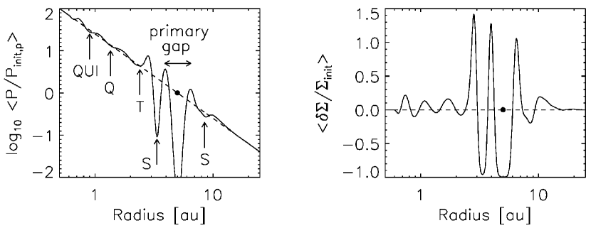
The radial gas pressure distribution after 200 kyr (18000 orbits) of evolution is shown in Figure 10. The core excites five spiral arms interior to its orbit and two spiral arms exterior to its orbit. Each spiral arm opens a gap through shock dissipation and pressure maxima form in between the gaps. In total, the core creates four pressure bumps interior to its orbit and two pressure bumps exterior to its orbit.
To test whether these pressure bumps are strong enough to trap solid particles, we follow the analytic approach presented in Zhu et al. (2012). To briefly summarize, in order for a particle to be trapped in a pressure bump the drift velocity toward the pressure maximum has to be greater than two velocities: (1) the diffusion velocity by gas turbulence; and (2) the enhanced radial gas velocity within the gap caused by the deficit of gas. The second requirement assumes a constant mass accretion rate across the ring and gap. One assumption has to be made to use this analytic approach is that the shape of additional gaps are similar to the main gap within which the planet orbits, as described by Equation (24) in Zhu et al. (2012).
Using , Equation (27) of Zhu et al. (2012) can be rearranged as
| (2) |
where is the solid particle density, is the radius of the solid particle, is the gas surface density, is the dust depletion factor. Now, let us consider a mm-sized particle placed right outside of the inner tertiary gap at au to examine whether it will be dragged into the inner disk or dragged outward to be trapped at the inner secondary pressure bump at au, as an example. Considering a spherical solid particle with a density of and a radius of and adopting disk gas density of , a disk viscosity of is required for the particle to penetrate the tertiary gap via turbulent diffusion assuming a dust depletion factor of as in Zhu et al. (2012):
| (3) | |||||
As shown in the above equation, increases inversely proportional to the gas surface density for a given solid particle density. Therefore, when all the pressure bumps beyond 2 au satisfy this first condition to trap solid particles with sizes of a mm or greater.
One can do the same experiment for the second condition about the enhanced gas velocity. Rearranging Equation (30) of Zhu et al. (2012), we obtain
| (4) |
where . Assuming again canonical values for a mm-sized particle placed right outside of the inner tertiary gap at au with a of gas depletion in the gap (i.e., ), a disk viscosity of is required for the particle to penetrate the tertiary gap:
| (5) | |||||
Based on Equations (3) and (5), we can infer that solid particles with sizes of mm can remain trapped in the inner primary and secondary and the outer primary and secondary pressure bumps when the disk viscosity is sufficiently low: . We note however that this is an value associated with the radial mass transport only, because the analysis presented above considers only the radial movement of gas and dust. Since disk turbulence can be anisotropic such that vertical stress is significantly stronger than the radial stress (e.g., Stoll et al., 2017), we caution that this value should not be taken as a representative value for the total disk turbulence.
It has to be noted that the simulation presented in this section assumes zero kinematic disk viscosity222Non-zero numerical viscosity can exist at a level of .. Using a non-zero kinematic viscosity will result in less prominent pressure bumps. On the other hand, the core will generate stronger spiral arms as it grows to a full Jupiter-mass and can create strong enough pressure bumps to trap solid particles even in the presence of a moderate viscosity (e.g., ; Bae et al. 2017).
Having multiple pressure bumps helps prevent solid particles from rapidly drifting inward, but their different strengths and locations in the disk can naturally explain the range of sizes and abundances of CAIs (and chondrules) seen in meteorites. Follow-up studies, which incorporate growth of the core with more realistic disk thermal evolution and gas-dust interaction, are certainly required to further examine this scenario. Nevertheless, formation of multiple pressure bumps by a growing Jupiter seems to be an intriguing possibility to explain the meteoritic property in the solar system and deserves further consideration.
6 SUMMARY AND DISCUSSION
We examined how characteristics of planet-driven spiral arms, including the number of spiral arms, pitch angle of spiral arms, and arm-to-arm separation, change as a function of disk temperature and planet mass, aiming to utilize the characteristics of observed spiral arms to constrain the mass of unseen planet and/or its position in the disk. To summarize the findings:
-
1.
A larger number of spiral arms form (1) with a smaller planet mass and (2) with a smaller (Figure 3). Our parameter study shows that three or fewer spiral arms are excited interior to a planet’s orbit when and two spiral arms when . The number of spiral arms exterior to a planet’s orbit is more sensitive to the disk temperature than the planet mass. Two outer spiral arms can excite when ; for warmer disks only one outer spiral arm launches.
-
2.
Using the pitch angle of spiral arms to constrain the mass of unseen planet requires accurate disk gas temperature measurements. However, because the pitch angles of planet-driven spiral arms always decrease away from the planet, this property can be a powerful diagnostic to determine whether the unseen planet is located interior or exterior to the observed spiral arms.
-
3.
The arm-to-arm separation increases as a function of planet mass and converges to for sufficiently massive planets (Figure 6 and 8); the exact mass depends on . Overall, our best fit to primary-to-secondary separation and planet mass is , which is in a good agreement with the relation provided by Fung & Dong (2015). However, we find that the arm-to-arm separation increases more steeply with the planet mass at smaller radii and for smaller values.
-
4.
The relative brightness/intensity of observed spiral arms is not an ideal characteristic to determine whether a certain spiral arm is a primary or a secondary/tertiary arm because secondary/tertiary arms can create stronger perturbation than the primary arm.
We then applied these diagnostics to the spiral arms seen in MWC 758 and Elias 2–27. For the MWC 758 disk, it is unlikely that the recently detected point-like source excites all three spiral arms. A more likely explanation is that the point-like source excites one of the spirals (S3 in Reggiani et al. 2017) and another yet undetected companion beyond 0.”6 from the star excites the other two (S1 and S2 in Reggiani et al. 2017). This scenario explains observed characteristics of the spiral arms reasonably well, including the radially decreasing pitch angle of the newly detected spiral arm in Reggiani et al. (2017) and the non-detection of this arm in previous observations at a shorter wavelength (Benisty et al., 2015). If this is the case, observations in 2018 may reveal more than of difference in the orbital motions between S3 and the other two compared with the first epoch observation of Reggiani et al. (2017) taken in 2015 October.
For the Elias 2–27 disk, we emphasize that the measured constant pitch angle in Pérez et al. (2016) is not an expected characteristic of planet-driven spiral arms, unless the actual disk temperature profile over the region spirals extend is much steeper than what is currently constrained: or steeper vs. . We conjecture that having a constant pitch angle might be a generic feature of GI-driven spiral arms. More accurate measurements of the disk gas surface density distribution as well as theoretical developments on GI-driven spiral arms will help reveal the true nature of the two-armed spirals in the Elias 2–27 disk.
We carried out a numerical simulation to show that spiral arms driven by Jupiter’s core in the solar nebula could have created multiple gaps and pressure bumps through spiral shocks. Some of the pressure bumps can be strong enough to trap solid particles of appropriate sizes, which can help explain the extended duration of meteorite parent body accretion as well as the broad range of sizes and abundances of CAIs seen in meteorites.
The analysis presented in this paper is based on two-dimensional numerical simulations. As recent three-dimensional simulations have shown, planet-driven spiral arms have a three-dimensional structure in a way that they are curled toward the central star and produce larger perturbations near the disk surface (Zhu et al., 2015). Vertical temperature gradient can also affect the propagation of waves (Lubow & Ogilvie, 1998; Bate et al., 2002; Lee & Gu, 2015). More thorough analysis using three-dimensional simulations is hence guaranteed, which we will address in future papers.
| Radius | Best Fits | |
|---|---|---|
| * | ||
| * | ||
| 0.05, 0.06 | * | |
| * | ||
| * | ||
| * | ||
| 0.07, 0.08 | ||
| * | ||
References
- Andrews et al. (2009) Andrews, S., Wilner, D. J., Hughes, A. M., et al. 2009, ApJ, 700, 1502
- Bae et al. (2014) Bae, J., Hartmann, L., Zhu, Z., & Nelson, R. P. 2014, ApJ, 795, 61
- Bae et al. (2016a) Bae, J., Zhu, Z., & Hartmann, L. 2016a, ApJ, 819, 134
- Bae et al. (2016b) Bae, J., Nelson, R. P., Hartmann, L., & Richard, S. 2016b, ApJ, 829, 13
- Bae et al. (2017) Bae, J., Zhu, Z., & Hartmann, L. 2017, ApJ, 850, 201
- Bae & Zhu (2017) Bae, J., & Zhu, Z. 2017, accepted to ApJ(Paper I)
- Bate et al. (2002) Bate, M. R., Ogilvie, G. I., Lubow, S. H., & Pringle, J. E. 2002, MNRAS, 332, 575
- Benisty et al. (2015) Benisty, M., Juhász, A., Boccaletti, A., et al. 2015, A&A, 578, L6
- Benítez-Llambay & Masset (2016) Benítez-Llambay, P., & Masset, F. 2016, ApJS, 223, 11
- Budde et al. (2016a) Budde, G., Burkhardt, C., Brennecka, G. A., et al. 2016a, E&PSL, 454, 293
- Budde et al. (2016b) Budde, G., Kleine, T., Kruijer, T. S., et al. 2016b, PNAS, 113, 2886
- Connelly et al. (2012) Connelly, J. N., Bizzaro, M., Krot, A. N., et al. 2012, Sci, 338, 651
- Desch et al. (2017) Desch, S. J., Kalyaan, A., & Alexander, C. M. O. 2017, arXiv:1710.03809
- Dong et al. (2015) Dong, R., Zhu, Z., Rafikov, R. R., & Stone, J. M. 2015, ApJ, 809, L5
- Dong et al. (2017) Dong, R., Li, S., Chiang, E., & Li, H. 2017, ApJ, 843, 127
- Dong & Fung (2017) Dong, R., & Fung, J. 2017, ApJ, 835, L38
- Fedele et al. (2018) Fedele, D., Tazzari, M., Booth, R., et al. 2018, A&A, 610, A24
- Fung & Dong (2015) Fung, J., & Dong, R. 2015, ApJ, 815, L21
- Gaia Collaboration et al. (2016) Gaia Collaboration, Brown, A. G. A., Vallenari, A., et al. 2016, A&A, 595, A2
- Garufi et al. (2013) Garufi, A., Quanz, S. P., Avenhaus, H., et al. 2013, A&A, 560, A105
- Ginski et al. (2016) Ginski, C., Stolker, T., Pinilla, P., et al. 2016, A&A, 595, A112
- Goldreich & Tremaine (1978a) Goldreich, P., & Tremaine, S. 1978a, Icarus, 34, 240
- Goldreich & Tremaine (1978b) Goldreich, P., & Tremaine, S. 1978b, ApJ, 222, 850
- Goldreich & Tremaine (1979) Goldreich, P., & Tremaine, S. 1979, ApJ, 233, 857
- Goodman & Rafikov (2001) Goodman, J., & Rafikov, R. R. 2001, ApJ, 552, 793
- Grady et al. (2013) Grady, C. A., Muto, T., Hashimoto, J., et al. 2013, ApJ, 762, 48
- Hayashi (1981) Hayashi, C. 1981, Progress of Theoretical Physics Supplement, 70, 35
- Isella et al. (2010) Isella, A., Natta, A., Wilner, D., et al. 2010, ApJ, 725, 1735
- Juhász et al. (2015) Juhász, A., Benisty, M., Pohl, A., et al. 2015, MNRAS, 451, 1147
- Kanagawa et al. (2015) Kanagawa, K. D., Muto, T., Tanaka, H., et al. 2015, ApJ, 806, L15
- Kita & Ushikubo (2012) Kita, N. T., & Ushikubo, T. 2012, M&PS, 47, 1108
- Kruijer et al. (2017) Kruijer, T. S., Burkhardt, C., Budde, G., & Kleine, T. 2017, PNAS, 114, 6712
- Lee & Gu (2015) Lee, W.-K. & Gu, P.-G. 2015, ApJ, 814, 72
- Lee (2016) Lee, W.-K. 2016, ApJ, 832, 166
- Lin & Papaloizou (1993) Lin, D. N. C., & Papaloizou, J. C. B. 1993, Protostars and Planets III, ed. E. H. Levy & J. I. Lunine (Tucson, AZ: Univ. Arizona Press),749
- Lubow & Ogilvie (1998) Lubow, S. H. & Ogilvie, G. I. 1998, ApJ, 504, 983
- Luhman & Rieke (1999) Luhman, K. L., & Rieke, G. H. 1999, ApJ, 525, 440
- Maire et al. (2017) Maire, A.-L., Stolker, T., Messina, S., et al. 2017, A&A, 601, A134
- Meeus et al. (2012) Meeus, G., Montesinos, B., Mendigutía, I., et al. 2012, A&A, 544, A78
- Meru et al. (2017) Meru, F., Juhász, A., Ilee, J. D., et al. 2017, ApJ, 839, L24
- Muto et al. (2012) Muto, T., Grady, C. A., Hashimoto, J., et al. 2012, ApJ, 748, L22
- Pinilla et al. (2012) Pinilla, P., Birnstiel, T., Ricci, L., et al. 2012, A&A, 538, A114
- Pérez et al. (2016) Pérez, L. M., Carpenter, J. M., Andrews, S. M., et al. 2016, Sci, 353, 1519
- Reggiani et al. (2017) Reggiani, M., Christiaens, V., Absil, O., et al. 2017, arXiv:1710.11393
- Shu (2016) Shu, F. H. 2016, ARA&A, 54, 667
- Stolker et al. (2016) Stolker, T., Dominik, C., Avenhaus, H., et al. 2016, A&A, 595, 113
- Stolker et al. (2017) Stolker, T., Sitko, M., Lazareff, B., et al. 2017, accepted to ApJ, arXiv:1710.02532
- Stoll et al. (2017) Stoll, M.H.R., Kley, W., & Picogna, G. 2017, A&A, 599, 6
- Tang et al. (2017) Tang, Y.-W., Guilloteau, S., Dutrey, A., et al. 2017, ApJ, 840, 32
- Warren (2011) Warren, S. J. 2011, Icarus, 67, 164
- Weidenschilling (1977) Weidenschilling, S. J. 1977, AP&SS, 51, 153
- Zhu et al. (2012) Zhu, Z., Nelson, R. P., Dong, R., Espaillat, C., & Hartmann, L. 2012, ApJ, 755, 6
- Zhu et al. (2014) Zhu, Z., Stone, J. M., Rafikov, R. R., & Bai, X.-N. 2014, ApJ, 785, 122
- Zhu et al. (2015) Zhu, Z., Dong, R., Stone, J. M., & Rafikov, R. R. 2015, ApJ, 813, 88