Christian Schüller, Roi Poranne, Olga Sorkine-Hornung
![[Uncaptioned image]](/html/1711.02450/assets/figs/teaser/teaser.jpg)
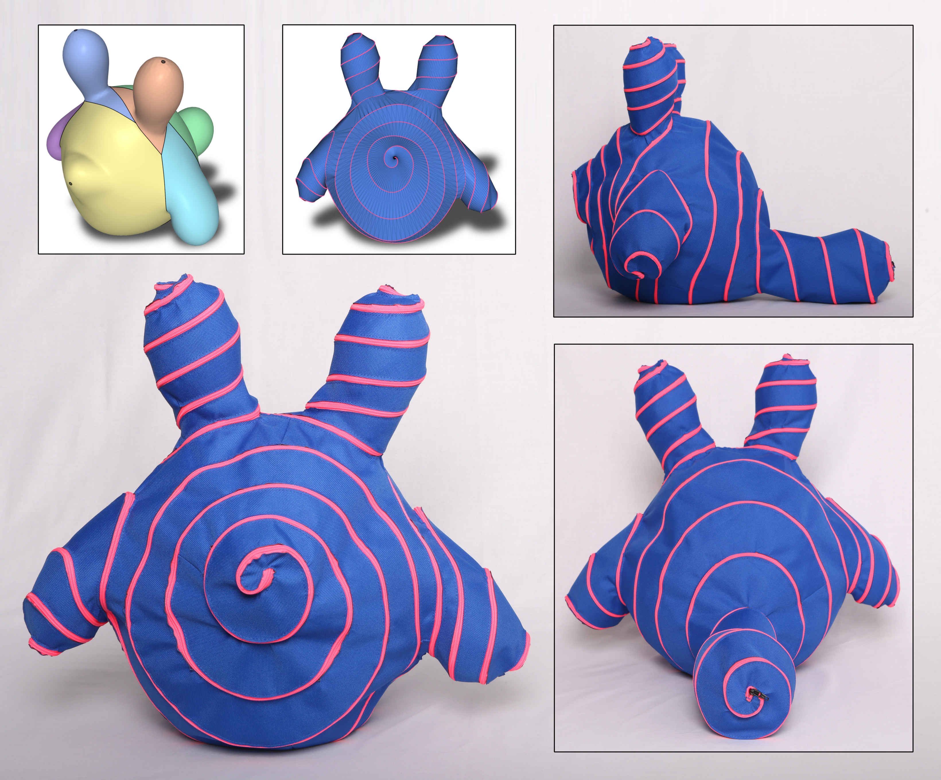
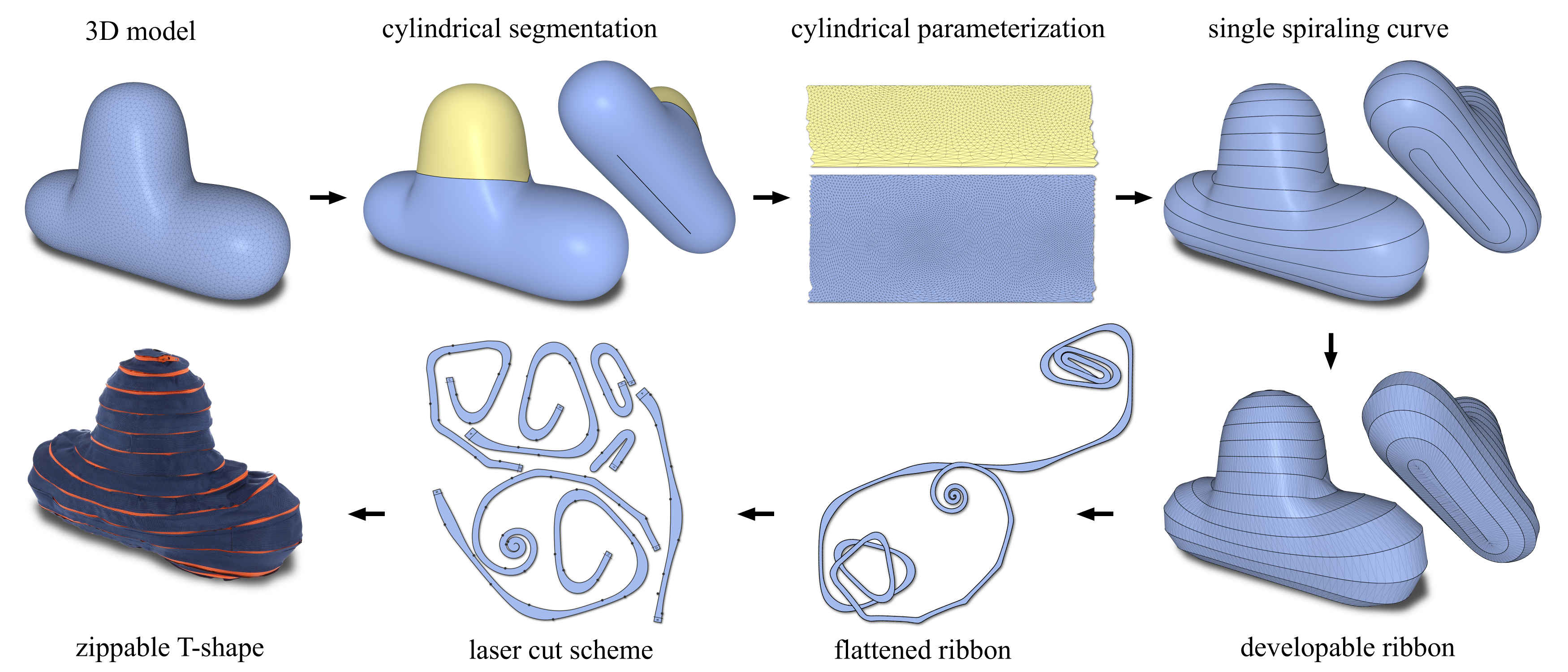
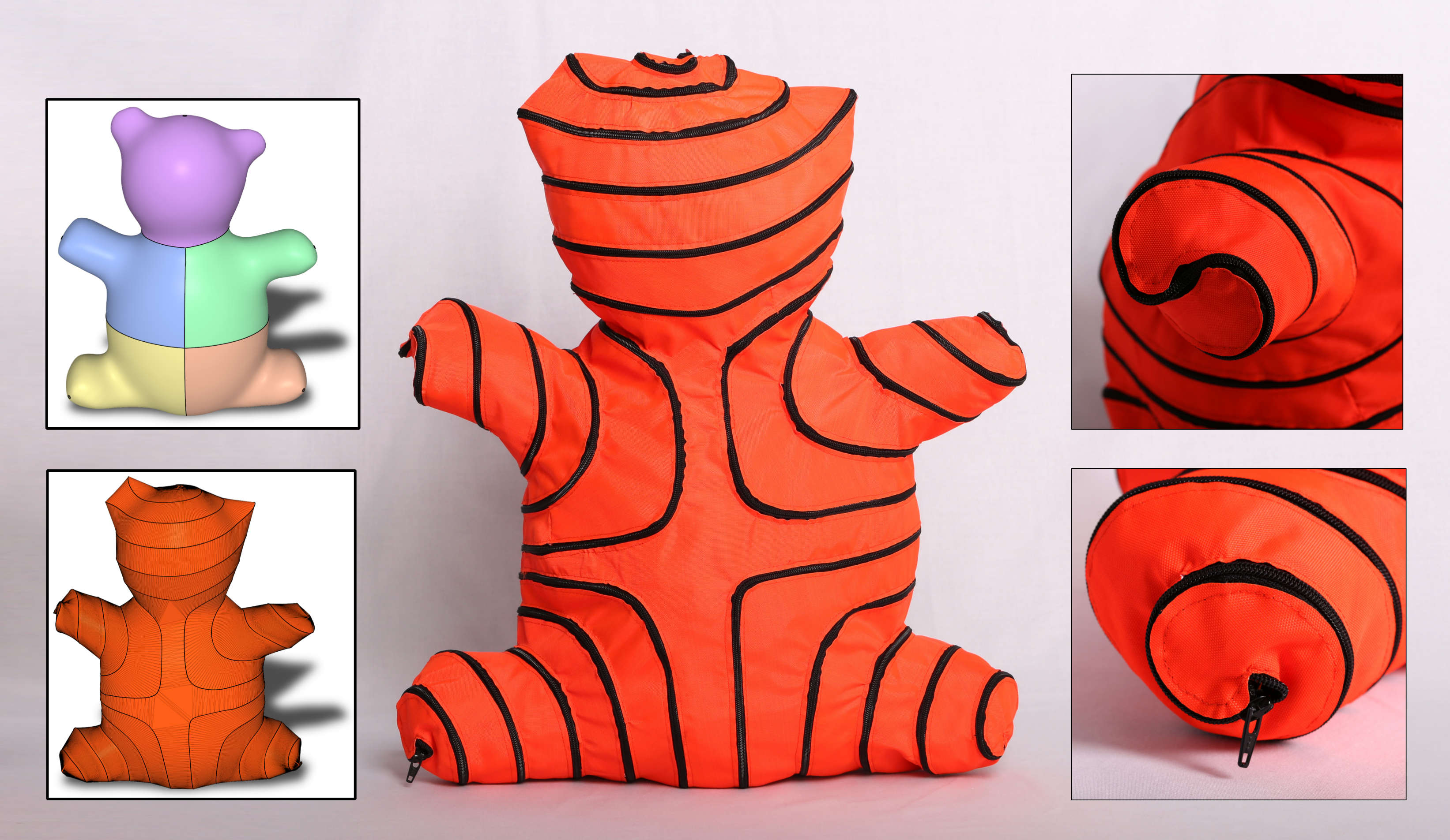
The pipeline of our approach. Starting from a 3D model the user segments the shape into topological cylinders. Our algorithm then produces a curve on the shape that spirals along the cylinders. It proceeds to cut the shape along the curve and creates a single, developable ribbon-like surface. The ribbon is flattened into 2D and, based on the flattening, plans for laser cutting the ribbon out of fabric are generated. Finally, we stitch a single zipper to the boundary of the ribbon. Zipping it up reproduces the original shape.
Shape Representation by Zippable Ribbons
Abstract
Shape fabrication from developable parts is the basis for arts such as papercraft and needlework, as well as modern architecture and CAD in general, and it has inspired much research. We observe that the assembly of complex 3D shapes created by existing methods often requires first fabricating many small flat parts and then carefully following instructions to assemble them together. Despite its significance, this error prone and tedious process is generally neglected in the discussion. We propose an approach for shape representation through a single developable part that attaches to itself and requires no assembly instructions. Our inspiration comes from the so-called zipit bags [\citenamezipit 2017], which are made of a single, long ribbon with a zipper around its boundary. In order to “assemble” the bag, one simply needs to zip up the ribbon. Our method operates in the same fashion, but it can be used to approximate any shape. Given a 3D model, our algorithm produces plans for a single 2D shape that can be laser cut in few parts from flat fabric or paper. We can then attach a zipper along the boundary for quick assembly and disassembly, or apply more traditional approaches, such as gluing and stitching. We show physical and virtual results that demonstrate the capabilities of our method and the ease with which shapes can be assembled.
1 Introduction
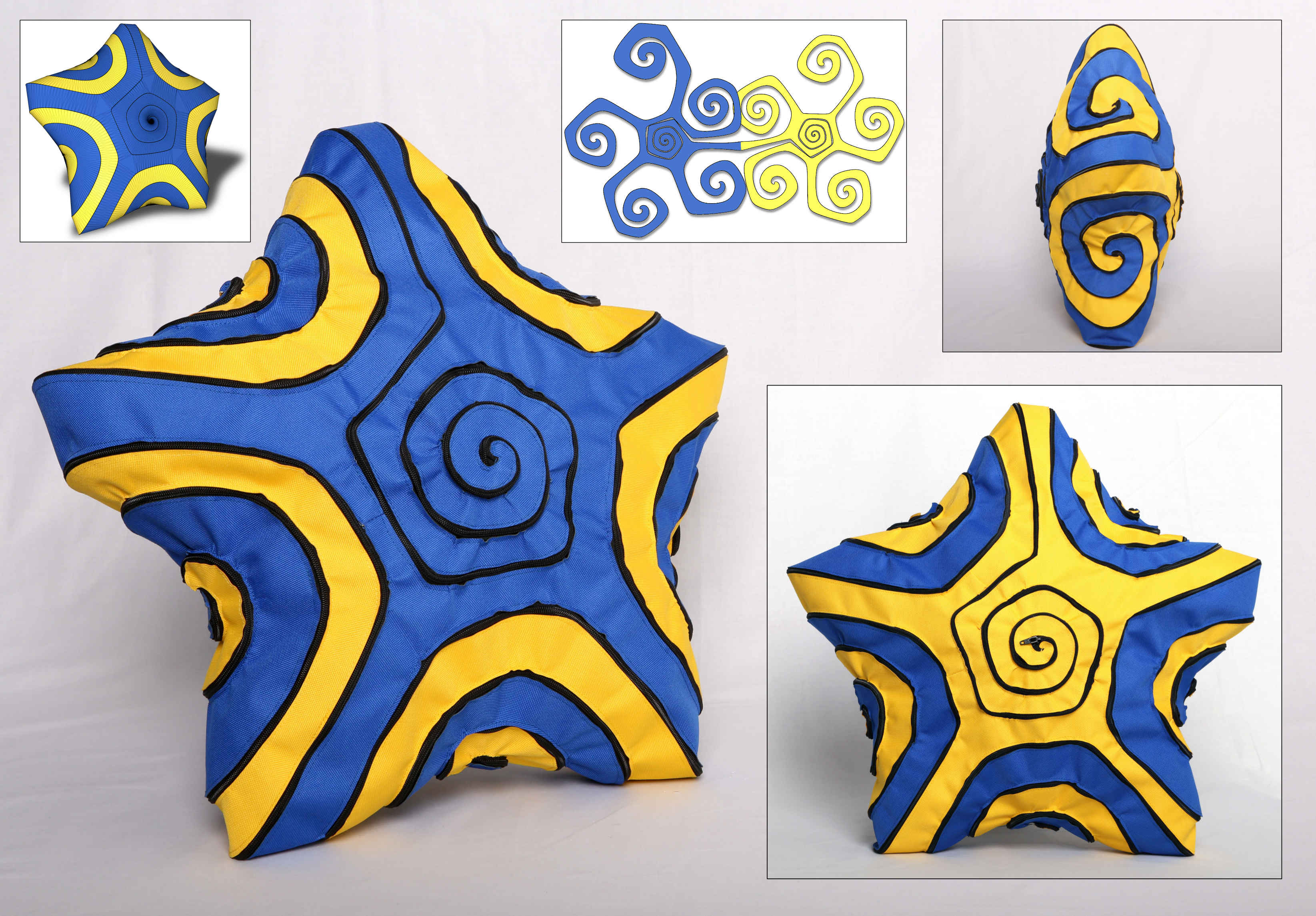
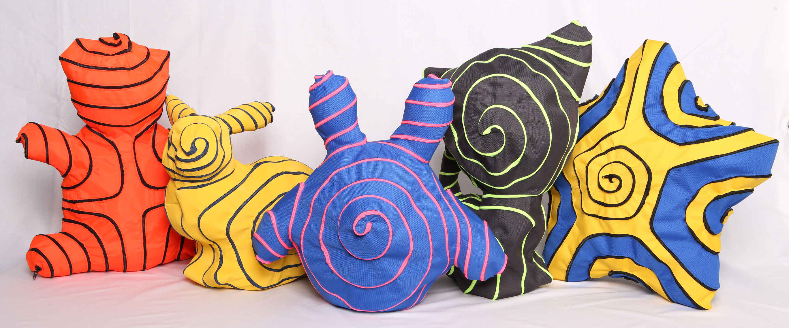
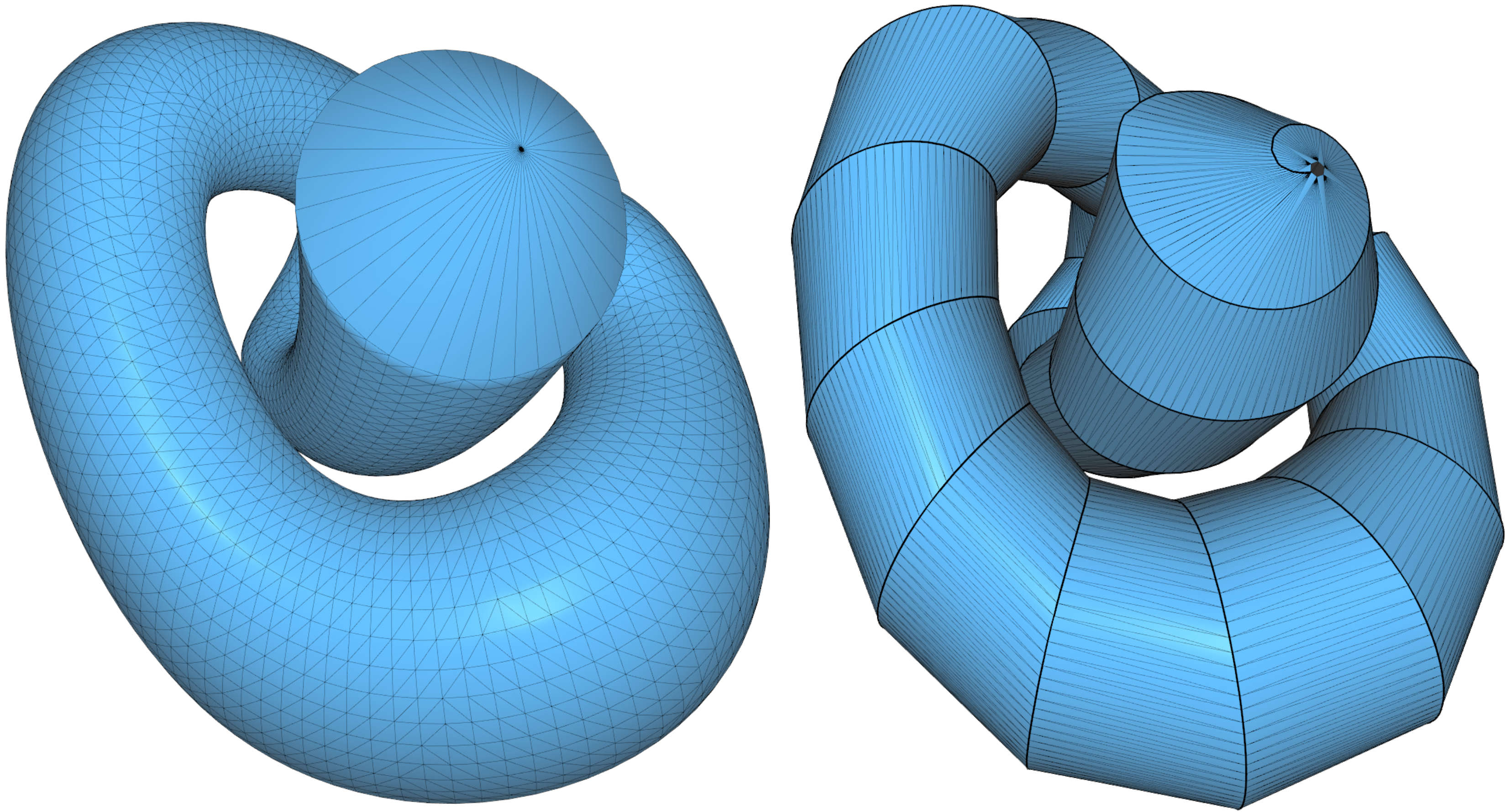
Representing shapes using developable surfaces is a problem with numerous applications, ranging from recreational activities like papercraft fabrication, to large scale industrial design and modern architecture. Our interest in this problem is inspired by a product commercially known as the zipit bag [\citenamezipit 2017]. This bag is made from a single, long piece of fabric ribbon with a zipper attached around its boundary. When zipped up, the ribbon wraps around to form a simple bag. It takes only a few seconds to assemble and disassemble it, and no instructions are necessary. The simplicity of this concept and the oddly satisfying sensation of seeing it taking form when being zipped up immediately propelled us to ask whether this idea can be generalized to arbitrary shapes. To this end, we devise a computational method to create a suitable developable shape that approximates a given target 3D model when zipped up; see e.g. Fig. Shape Representation by Zippable Ribbons. Our approach generalizes the simple straight ribbons that make up the zipit bags by allowing the ribbons to turn, have varying width, and branch (see Fig. 1).
Merely finding a 2D shape that approximately reproduces a 3D shape when zipped up is not very challenging. One approach would be to take a 3D mesh and cut it into a single triangle strip [\citenameRossignac 1999, \citenameEppstein and Gopi 2004]. However, in addition to being mesh dependent, the resulting strip would have many sharp turns that make zipping up difficult, if not impossible, and the strip’s width would be uneven, which can be visually unappealing. Therefore, we postulate the following desirable “regularity” properties for a zippable 2D ribbon shape:
-
•
The ribbon should curve as little as possible.
-
•
It should have as constant as possible width.
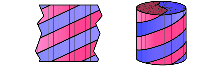
The challenge we aim to solve is to compute a single, flat piece that satisfies these two properties and approximates the input shape well when zipped up. We observe that the two properties are nearly trivial to achieve when the target 3D model is a cylinder: it is easy to trace a spiraling curve on a cylindrical surface such that if cut along that curve, the resulting shape is a straight ribbon with fixed width.
For general target surfaces, our approach is based on first decomposing the shape into topological cylinders, and then mapping them onto cylindrical domains with low isometric distortion and in a seamless manner. We then draw “perfect” spirals on the cylinders and map these spirals back onto the input shape.
![[Uncaptioned image]](/html/1711.02450/assets/x1.png)
Since the mappings minimize isometric distortion, the mapped curves tend to exhibit low curvature and low variation of the distance between windings. Inspired by [\citenameZhao et al. 2016] we connect the spirals on the different cylinders into a single, long Fermat spiral (see inset). The shape is then cut along the computed curve to create a single, possibly bifurcated, but not yet developable ribbon. A simple remeshing process then transforms this ribbon into a developable one, which can be trivially unfolded onto the 2D plane to create the cutting pattern. It is possible that some strands of the flat ribbon overlap in the plane, and the pattern might take up too much space to fully fit onto the laser cutter bed; in both cases we simply divide the ribbon into a few separate pieces that are later sewn back together, before attaching the zipper (see Fig. 16).
In addition to the assembly process being easy and entertaining, our fabrication process has distinct advantages over papercraft and many other similar methods in this domain. Our assembly is linear, i.e., at every instant of the assembly process, the next action is unique and unambiguous, and it requires no instructions. In contrast, papercraft and related approaches typically require certain assembly order, especially for the final stages, where all the parts have to come together for the shape to close up; the makers usually must refer to a manual, find the next piece and understand how to attach it to their work. In case our method generates self-overlapping strands of ribbon that must be severed in order to laser-cut them from fabric, sewing the pieces together is simple since both ends are flat, perfectly matching in length and only require flat stitching along a straight line. Also sewing the zipper to the ribbon only requires working on flat sheets of fabric and is therefore straightforward and rather fast, as confirmed by the seamsters and seamstresses we employed. In contrast, attaching multiple parts in papercraft or sewing plush toys from multiple charts usually cannot be done in a flat position, and may necessitate more time and skill for large models.
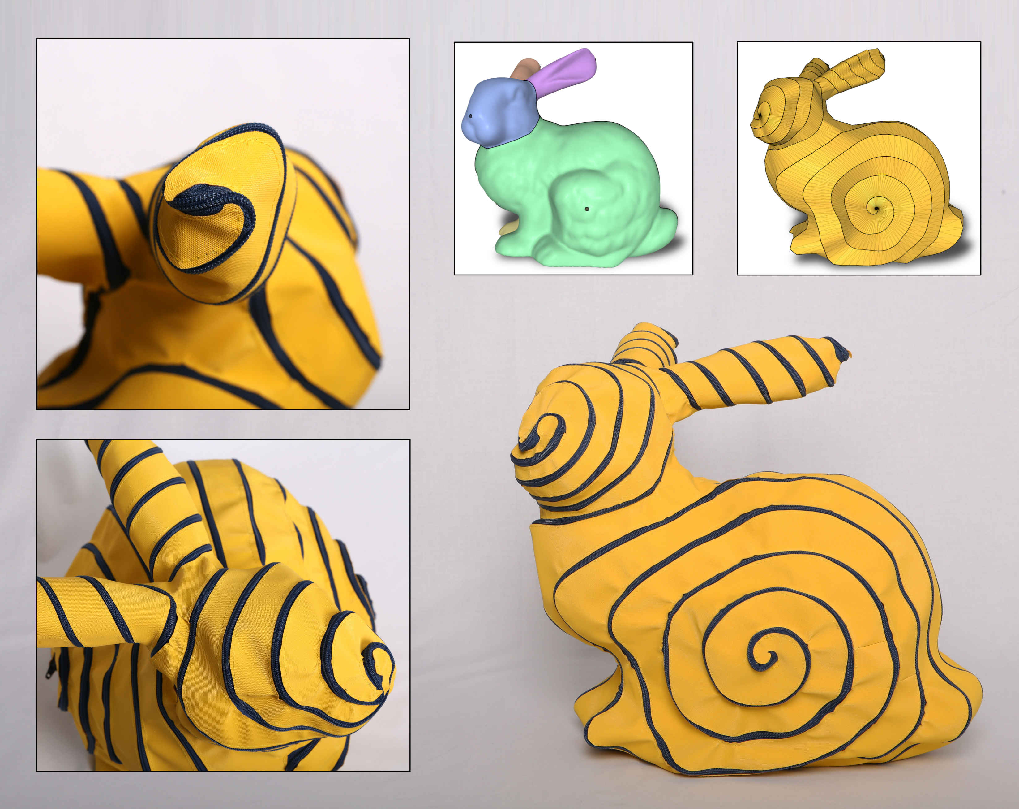
We demonstrate our technique on a number of various shapes, see e.g. the model in Fig. 2. We show virtual results and physically fabricated objects, which are assembled and disassembled simply by slider a zipper.
2 Related work
Our work relates to the general field of computational fabrication and digital geometry processing. We briefly review the most relevant previous works below.
Papercraft and needlework.
Some objects, typically of limited size and/or with certain constraints on the shape, can be directly manufactured in one piece using e.g. 3D printing or CNC milling. However, a large number of approaches propose to create shapes composed of several individually fabricated parts. In this space, the most related approaches to ours are papercraft based on cutting and gluing [\citenameMitani and Suzuki 2004, \citenameShatz et al. 2006, \citenameMassarwi et al. 2007, \citenameStraub and Prautzsch 2011, \citenameTakahashi et al. 2011], and manufacturing by sewing [\citenameJulius et al. 2005, \citenameMori and Igarashi 2007, \citenameIgarashi and Igarashi 2008, \citenameIgarashi et al. 2009, \citenameWang 2010, \citenameMahdavi-Amiri et al. 2015]. Both types of methods require the approximation of a given 3D shape by pieces of developable surfaces (in the case of paper) or highly stretch-resistant material (in the case of fabric). This is typically achieved by segmenting or cutting the shape into parts with low Gaussian curvature and parameterizing each part onto the plane. Alternatively, the shape can be a priori modeled or approximated as a piecewise developable surface, which is a current topic of active research [\citenameKolmianič and Guid 2002, \citenameRose et al. 2007, \citenameKilian et al. 2008, \citenameLiu et al. 2009, \citenameZeng et al. 2012, \citenameChandra et al. 2015, \citenameTang et al. 2016]. The assembly by gluing or sewing the pieces together requires precision and carefully following the instructions. In contrast, in our case, it is mostly a straightforward and even mindless task.
Soft materials.
Designing for fabrication using soft material like fabric or rubber is challenging, since such materials easily deform under stress and gravity. The main goal is to predict the deformation and solve an inverse problem, so that the fabricated model assumes the desired shape when subjected to the stress. Examples include the generation of plush toys [\citenameMori and Igarashi 2007, \citenameIgarashi and Igarashi 2008], inflatable structures [\citenameSkouras et al. 2012, \citenameSkouras et al. 2014] and rubber objects [\citenameBickel et al. 2010, \citenameSkouras et al. 2013, \citenameChen et al. 2014], among others. As mentioned, although we use fabric in our results, the behavior is more reminiscent of papercraft, because we use a nearly inextensible cloth and the zipper itself is rather stiff and completely inextensible. Regardless of the type of fabric used, our zipper based approach has one decisive advantage: The whole fabrication process can be done entirely in the flat. In contrast, previous methods result in spaciously curved pieces once they get connected to each other, which makes sewing or gluing much harder as confirmed by professional tailors. The final assembly by zipping up needs no instructions, is fast and fun to do.
Parameterization.
Our approach relies on mesh parameterization, which is an extensively studied topic, see e.g. the survey in [\citenameHormann et al. 2007]. The more recent relevant parameterization literature is presented in [\citenameSmith and Schaefer 2015, \citenameKovalsky et al. 2016, \citenameRabinovich et al. 2017]. Our method introduces a new type of global parameterization, which extends cylindrical parameterization [\citenameTarini 2012]. Global parameterization is primarily used for quad meshing, where parts of seams in the parameter domain are related to each other by a rotation of integer multiples of . A recent review can be found in [\citenameBommes et al. 2013]. In our specific case, we require a different form of seamless mapping, based on cylindrical domains [\citenameRay et al. 2006, \citenameKnöppel et al. 2015]. Our main inspiration is [\citenameKälberer et al. 2011], where the authors propose an approach for drawing stripes on tubular shapes that can be used for generating textures. Their approach is based on a seamless parameterization aligned with a 2-RoSy field obtained from the principal curvature directions. This causes problems near umbilical points, where the principal directions are unstable. In contrast, we employ parameterization based on distortion minimization, which avoids this problem, and generally leads to less distorted mappings [\citenameMyles and Zorin 2012].
3 Method
Given a mesh representing the 3D object, our goal is to generate a single, flat, possibly branching shape, which from now on we refer to simply as ribbon, that approximates the object when “zipped-up”. We can rigorously define zipping-up as an isometric deformation of the flat shape into a 3D shape such that the boundary exactly overlaps with itself. However, we assume that our intention is clear and avoid mathematical rigor at this point. In addition to being “zippable”, we wish to enable some creative control by allowing the user to define where the zipper should pass and how it should be oriented or aligned.
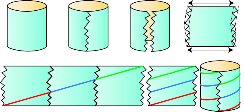
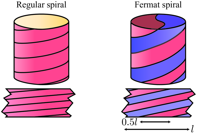
Our method is based on the observation that it is trivial to generate a perfect spiral on a cylinder. Assume the cylinder is a topological annulus (i.e., has no caps). We can cut it from its top boundary loop to the bottom one and unfold it to a rectangular shape, where the two boundary curves become the top and bottom edges, and the cut becomes the two side edges. We then place “copies” of the unfolded cylinder side-by-side, and draw a straight line from the bottom corner of the leftmost edge to the top corner of the rightmost edge. Overlaying the copies on top of each other creates several disconnected, parallel line segments on the parameterization of the cylinder, and by folding it back to a cylinder, these segments transform into a perfect connected spiral. Its number of turns depends on the number of copies we made. See Fig. 3 for an illustration.
The same approach, termed cylindrical parameterization, can be applied to general cylinder-like shapes, which we colloquially continue calling “cylinders”. We start in the same manner by cutting the shape from one boundary loop to the other. The cut shape is then mapped to the plane by a distortion minimizing parameterization with seam constraints, which force the two sides of the cut to match like puzzle pieces. Minimizing distortion is necessary for the straight line in 2D to be mapped to a smooth and uniform spiral on the surface in 3D. The case of a more complex shape is slightly more involved: we decompose the shape into cylindrical parts and use a global parameterization scheme to smoothly map all the parts to cylinders. We discuss this in more detail in Sec. 3.2.
Once the mapping is found, we turn to designing spirals on the cylinders. The main challenge is to synchronize the spirals, such that one spiral ends where another begins, resulting in a single, long, spiraling curve on the surface. The final task is to cut the surface along the curve and remesh it such that the result is developable. It is then trivially flattened to generate the final 2D shape of the zippable ribbon.
To summarize, the design phase of our method consists of four stages:
-
1.
Decomposition into cylindrical parts.
-
2.
Seamless, global parameterization of the cylinders.
-
3.
Spiral generation.
-
4.
Cutting along the spiral, remeshing and flattening.
See Fig. Shape Representation by Zippable Ribbons for a graphical overview.
3.1 Decomposition into cylindrical parts
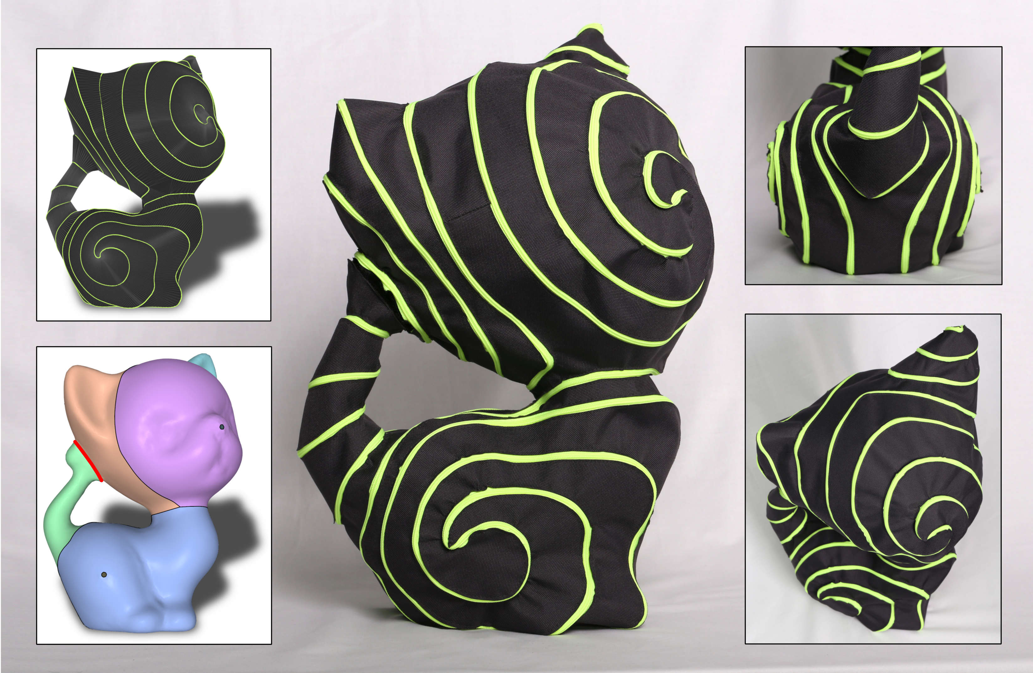
We decompose the input shape into topological cylinders , i.e., 2-manifolds with two boundary loops, more commonly termed annuli. The decomposition plays a substantial role in the final appearance of the spiral, since the resulting curve is aligned to the boundaries of the cylinders. It enables a flexible interface for artistic exploration and is achieved by interactively tracing the boundaries of the segmentation using our software. Alternatively, more automatic ways of cylindrical decomposition such as [\citenameZhou et al. 2015, \citenameLivesu et al. 2017] could be applied, but we have not explored this option. Since surfaces without boundaries cannot be decomposed into topological cylinders, we also allow the user to cut the shape open and place new boundaries, e.g., small circular holes or curves on the shape that act as a single cylinder boundary (see Fig. 5). We distinguish between transition boundaries separating two adjacent cylinders and open boundaries, which are actual boundaries of the shape. In the spiral design stage, the curve will pass through transition boundaries, spiraling in toward an open boundary and then spiraling out toward another open boundary. This behavior is reminiscent of the Fermat spiral, which we discuss in Sec. 3.3.
3.2 Seamless parameterization
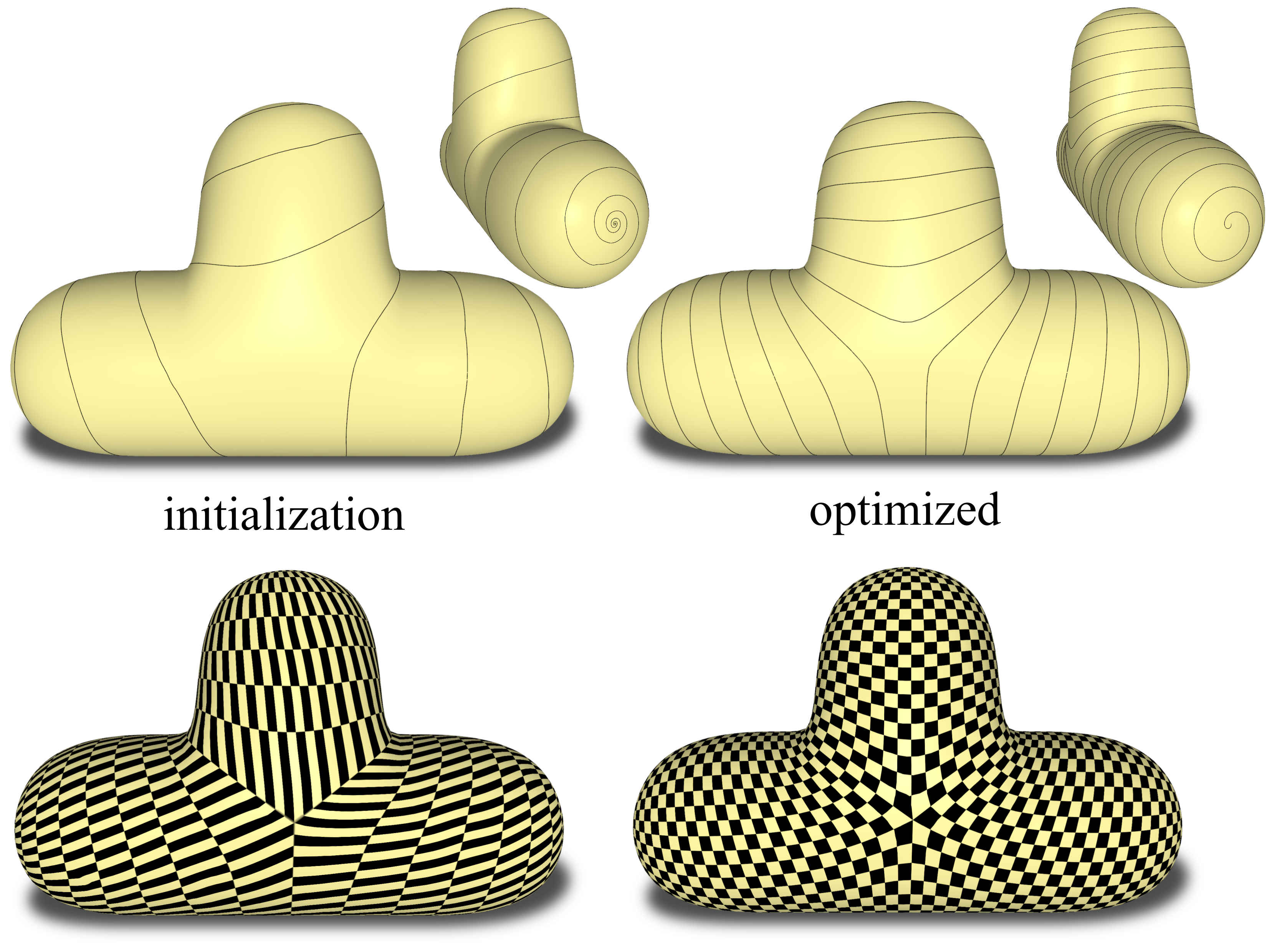
Once the cylindrical decomposition of into parts is available, we proceed to compute the parameterization. This step determines how the equally spaced, straight lines in the 2D parameter domain transform into spirals on . To obtain a spiral that maintains the even spacing on the 3D shape, the parameterization must minimize isometric distortion. Additionally, we require the parameterization to be bijective in order for the mapping from the 2D lines to the 3D curve to be well defined. Fig. 6 compares curves generated with the initial (i.e. suboptimal) and optimized parameterization.
We assume that has been cut along the boundaries of the ’s, and each cylinder is cut from one boundary to the other, analogous to the example of one cylinder (see Fig. 3 top row). The edges and vertices along the cuts are duplicated, and we keep correspondences between the copies. We generate a seamless bijective parameterization of each , with seamless transitions between adjacent ’s. We first explain the case where there is only one cylinder, and the general case of multiple cylinders immediately follows.
Minimizing isometric distortion.
An isometric distortion measure quantifies the difference between a given flattening of a shape and a perfect isometry; most formulations define it as a sum of the distortions of individual triangles. In this paper we use the recently proposed symmetric Dirichlet distortion measure; see [\citenameSmith and Schaefer 2015, \citenameKovalsky et al. 2016, \citenameRabinovich et al. 2017] for details.
We denote the coordinates of a vertex in the parameter domain by and stack all the coordinates in a vector . The distortion of a triangle is a function of the positions of its vertices in the plane. We denote the symmetric Dirichlet measure of triangle by . Then the optimization problem to solve is
| (1) |
where is the area of in the original mesh. In our work, we use a modified Newton’s method [\citenameShtengel et al. 2017] with a feasible starting point to solve this problem. Since we add several constraints in the following, we defer a detailed discussion to the end of this section.
Seamless cylindrical parameterization.
To map a single topological cylinder to the plane with minimal distortion in a seamless manner, it is cut to form a disk topology and then parameterized while adhering to seam constraints. The role of the seam constraints is to ensure that the parameterization is invariant to the cut [\citenameMyles and Zorin 2012]. In the cylinder case, the seam constraints call for each edge on one side of the seam to be a translation of its twin edge on the other side of the seam. More precisely, assume the cut contains consecutive vertices and let and , be the two copies of each vertex in the parameterization (superscripts stand for Left and Right). Then the cylindrical seamlessness constraints are
| (2) |
We use the differential form of the seam constraints in order to avoid introducing auxiliary variables. The equivalent positional form is where is an unknown offset (the same for all vertices). For conciseness, we refer to the set of constraints in (2) as for a given , or in general.
Cylinder boundary constraints.
In addition to the cylinder seam constraints , we also require the boundary loops
![[Uncaptioned image]](/html/1711.02450/assets/x3.png)
of the cylinders to be mapped to straight lines. This serves two purposes: First, together with the , it guarantees bijectivity, and second, it allows for a better surface coverage by the spiral. Indeed, when the boundaries are not kept straight and allowed to “spill out” in the 2D domain, the spilled region is not covered by the spiral (see illustration in the inset and Fig. 21). Due to , the straight lines of the boundaries must be parallel, hence, without loss of generality, we can make them parallel to the horizontal -axis. Let , and , be the -coordinates of the vertices of the top and bottom boundaries in the parameter domain. We again use the differential form for the straight line constraints, given by
| (3) |
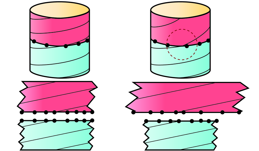
We denote the constraints of each in (3) by , and the entire set of these constraints as . The constraints and together already result in a nice spiral on each separately. However, without dedicated treatment, there could be a visible kink in the spiral when transitioning between ’s (see illustration in Fig. 7). Indeed, if copies of the same edge on a transition boundary are parameterized to two edges with different size and direction, then the parameterization will not appear smooth across that edge. We handle this issue in the following.
Inter-cylinder seamlessness.
In order for the transition between ’s to appear smooth, we apply seam constraints on cuts between each pair of neighboring ’s. These constraints enforce a rigid transformation between the two sides of each seam (see illustration in Fig. 7). Since we have the freedom to define the exact transformation, we choose a rotation by . Thus, for every two neighboring and , we let and , be the coordinates of the two copies of each vertex along the seam between and . Then the inter-cylinder seam constraints can be written in differential form as
| (4) |
We denote the constraints in (4) for each pair by .
Global cylindrical parameterization.
With all the types of constraints defined, we can formulate the optimization problem for parameterizing the surface:
| (5) | ||||||||
| s.t. | ||||||||
Eliminating degrees of freedom.
The constraints in (5) are all sparse linear homogeneous equalities, and they are overdetermined. For example, it is unnecessary to require all of the top and bottom boundaries to be on straight lines: it is sufficient to require this only for half of them, and the other half then must lie on straight lines due to the constraints. Similarly, the part of (5) is redundant due to the constraints. We remove these redundant constraints using Gaussian elimination.
Initialization.
Our optimization is based on Newton’s method and requires a feasible starting point with no triangle flips. We use Tutte’s embedding with uniform weights, which guarantees bijectivity if the boundary is convex. We can therefore map each cylinder to a rectangle in the plane, where the top and bottom boundaries are parallel to the axis, in order to satisfy . We set the height of each rectangle to have the length of the cylinder boundary in order to get a more isometric initial guess. In order to satisfy we require each edge of a transition boundary to have the same length in its parameterization. We can do the same for the cylinder boundary edges, which then completely determines the boundary. However, we note that we can in fact use , as they are in the form of an orbifold Tutte’s embedding (see [\citenameAigerman and Lipman 2015]), instead of specifying vertex positions directly, which results in a slightly less distorted initial guess.
Optimization.
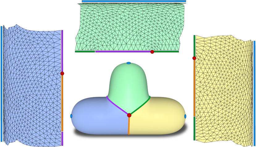
We use a modified Newton’s [\citenameShtengel et al. 2017] method with linear constraints to solve (5). We use the line search method suggested in [\citenameSmith and Schaefer 2015], which guarantees that no triangle flips are introduced during optimization. Once the optimization converges, we continue to the next step, which is the generation of the spirals. We show an example of the parameterization of the T shape in Fig. 8.
3.3 Spiraling curve design
With the global seamless parameterization of the cylindrical decomposition available, the next stage in our algorithm is to generate a spiraling curve on the shape by drawing straight lines on the flattening and lifting them back into 3D by the inverse mapping. A spiral on a single can be created as discussed in the beginning of Sec. 3, by drawing a straight line on the cylinder’s parameterization. For the case of multiple ’s, in order to obtain a single continuous curve, we must make sure that the spirals of the individual ’s connect. We make the following simplifying assumptions:
-
1.
The curve starts and ends at an open boundary, passes through each transition boundary and traverses all other open boundaries via Fermat spirals.
-
2.
Each has one transition boundary and one open boundary (see Sec. 3.1).
-
3.
The curve enters and exits each exactly once.
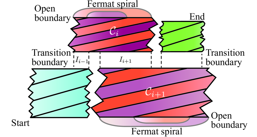
Note that a Fermat spiral requires drawing two lines on a cylinder (see Fig. 9). The assumptions above mean w.l.o.g. that a curve must start at an open boundary in , then cross a transition boundary and travel to the adjacent . Then touch its open boundary and leave it at another point to continue through the other transition boundary to . This continues until all cylinders are traversed, and the curve ends at the open boundary of the last . See Fig. 10 for an illustration.
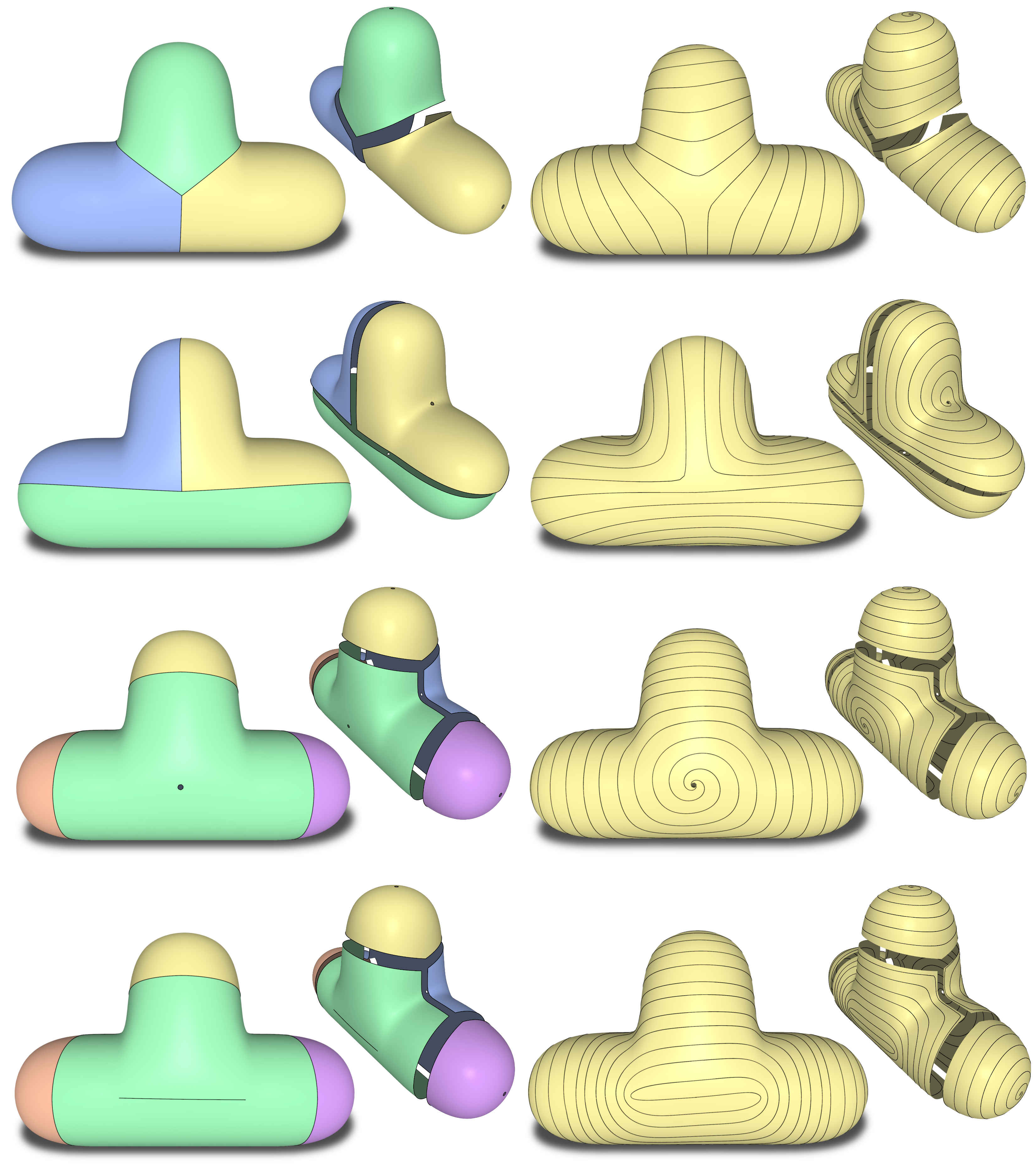
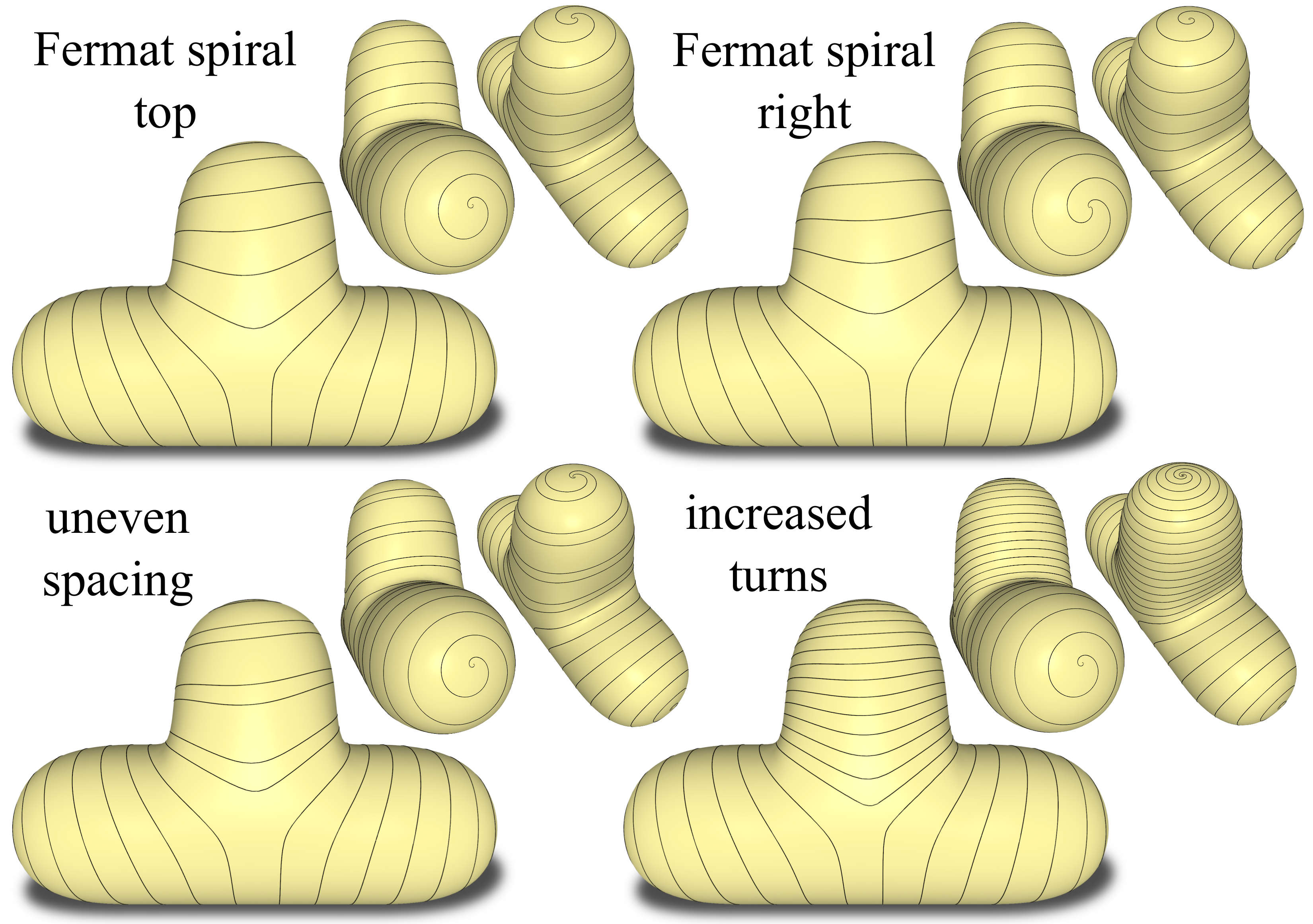
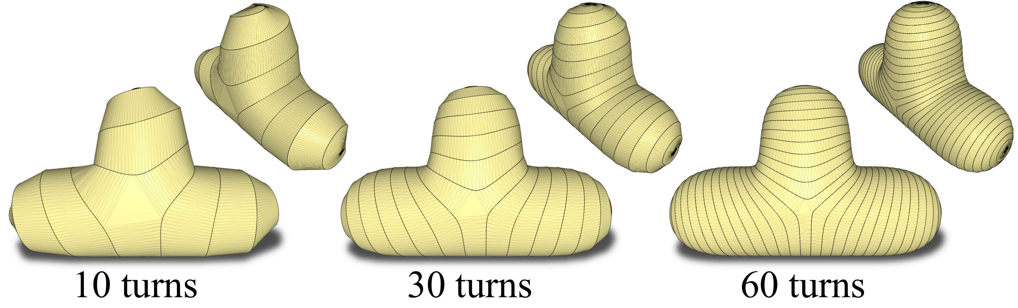
There are several choices we let the user make. The first one is the traversal order of the ’s. The second one is the location where the curve passes between and . Finally, the user can prescribe the number of windings of the spiral on each . See Fig. 11 for an example of the different choices. These choices impact the final look of the curve and should be based mostly on artistic considerations. Having as-uniform-as-possible spacing between the windings appears to be the best for practical fabrication reasons. For a regular spiral, even spacing is ensured by the low-distortion parameterization. The Fermat spirals require a bit more thought, since two lines are needed per . Ideally, we would like to draw the two lines parallel, such that their copies are equally spaced. This means that the distance between their intersections with the boundary is half its width (Fig. 9). This is not always possible though, since the interfaces between ’s might not allow it. To illustrate this, consider a single , which the curve traverses after and before (Fig. 10). The has an open boundary, and shares two transition boundaries with and on its other boundary. The two boundaries are parameterized to two straight line segments of the same length . For the open boundary, we are free to pick any two points with a distance between them. Let us assume that the coordinates of the opposite boundary are the interval . Then the interfaces with and are sub-intervals . We would like the curve to cross the boundary at two point such that . Clearly this is not always possible, but in practice, we did not find this to be an issue, since the user is given explicit control over these passing points. A possible future work is to solve an optimization problem that finds the best crossing points within those intervals when a problematic situation is encountered.
3.4 Cutting, remeshing and flattening
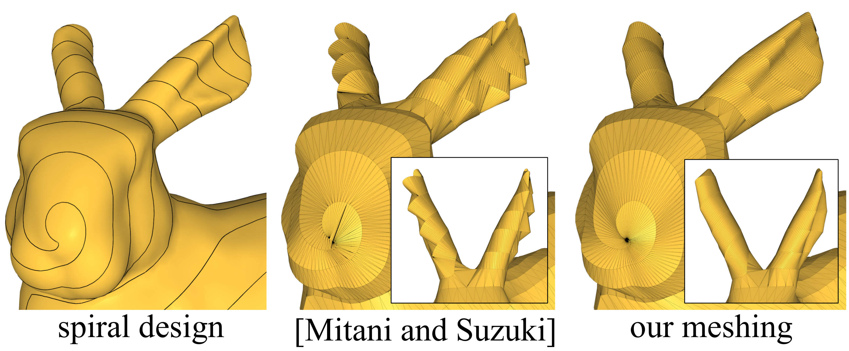
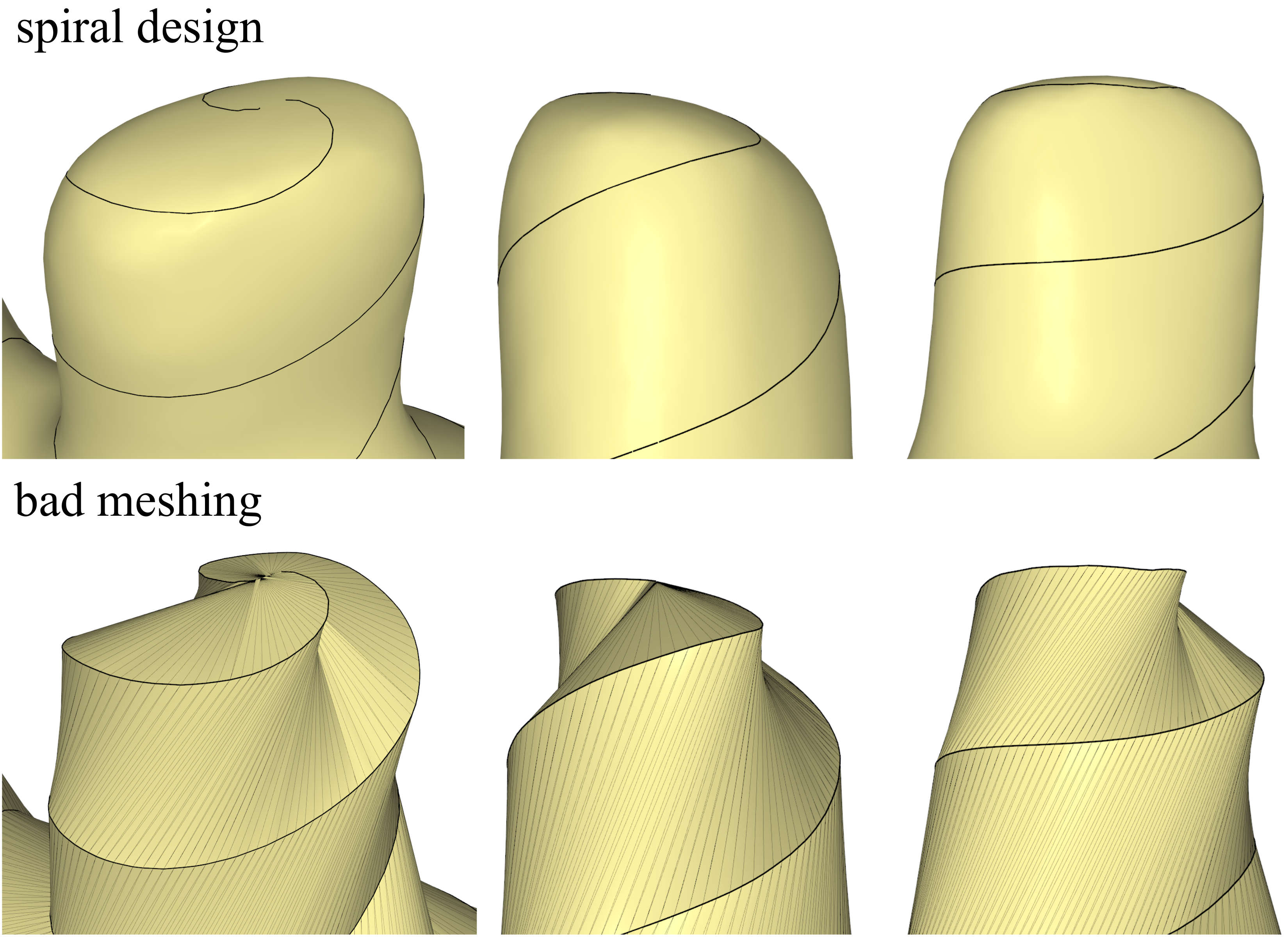
The goal of the final stage of our algorithm is to take the curve designed in the previous stage and look for a developable surface that has the curve as its boundary and approximates the shape well. This is a challenging task in general (see e.g. [\citenameRose et al. 2007, \citenameTang et al. 2016]), but it is somewhat simpler in the discrete setting. It is well known that a triangle mesh in 3D that has no internal vertices, i.e., all its vertices are boundary vertices, is developable. Finding a developable triangulation is still a difficult problem, where the challange lies in finding a meshing that appears smooth. Mitani and Suzuki \shortciteMitaniS04 proposed to use edge collapse and vertex removal operations until no internal vertices exist, and then to apply edge flip operations in order to improve the smoothness of the triangulation. We have implemented their method, but observed that the greedy edge flipping can introduce triangle fans near narrow curve turns (Fig. 12). We instead propose a simple approach based on the parameterization we already have from previous stages. The idea is to define correspondences between points on adjacent windings of the spiral, which act as rulings of a developable surface. The simple correspondence we choose is based on the coordinates of the lines in each ’s parameterization (Fig. 13). We sample these lines uniformly and connect two samples in adjacent windings if their coordinate is the same. We use Triangle [\citenameShewchuk 1996] to complete the triangulation where there is no natural correspondence, that is, around the interfaces between cylinders. Although this simple approach is not always optimal (see Fig. 20), we found it to be sufficient in most cases. Once the ribbon is triangulated, we can unfold it to the plane (see Fig. 16). We cut the ribbon into few smaller pieces in order to utilize the cutting area better and resolve overlaps.
4 Results and discussion
Implementation details.
We implemented all parts of our algorithm in C++, except the parameterization, which was implemented in MATLAB. The modified Newton’s method converges within at most 15 iterations and and takes about 20 seconds for a mesh with 30k triangles on our Xeon CPU E5-2650 v2, 64 GB RAM machine.
Approximation capabilities.
Naturally, the thinner the designed ribbon, the better its approximation power. However, this also results in a longer ribbon, prolonging the fabrication. The decision regarding the ribbon’s length and width is left to the user. See Fig. 14 for different widths and approximations of the T shape.
Papercraft comparison
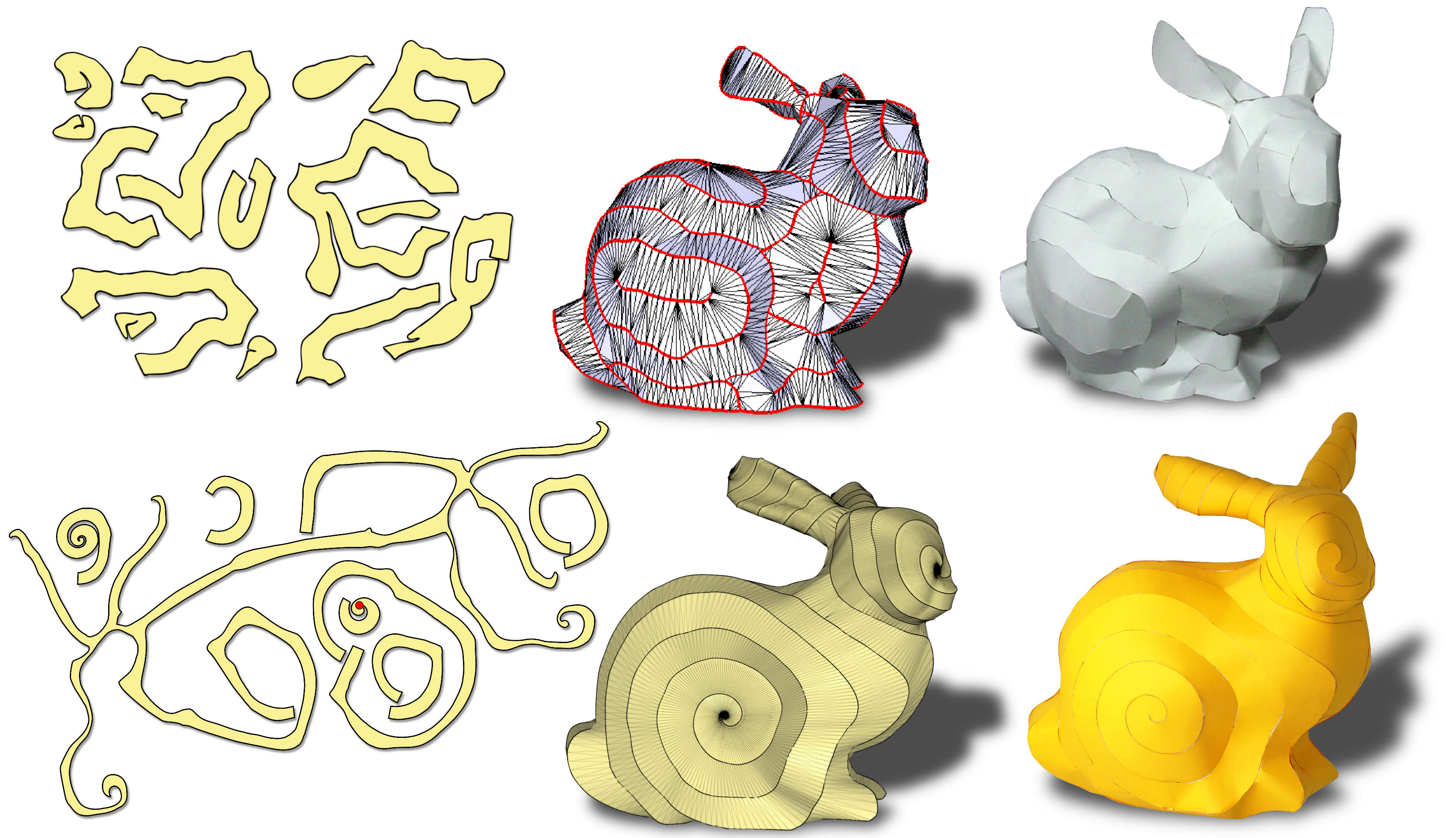
Our method can also be used to create papercraft models. In general, it produces fewer initial pieces then related methods and the assembly by gluing is straight forward and does not need elaborate instructions. See Fig. 15 for a comparison of our bunny result fabricated from paper with the method of [\citenameMitani and Suzuki 2004].
Fabrication process.
We fabricated six of our designs in fabric, see Figures 1, 2, 4, 16, 18, 19. Fig. 16 shows all the steps of our method with our simplest model, the T shape. All fabricated results have a zipper length of 10 meters, except the star, which has 11 meters. The models have a maximum size of around 50 cm. We asked professional tailors to do the sewing work, and it took them between 5 to 6 hours for each model. Even though they had no experience with this special kind of fabrication, there were no problems in attaching the zippers to the cut fabric pieces thanks to the linearity of the assembly method. To guarantee correct alignment of the zipper to the fabric, we place markers every 5 cm both on the zipper and along the laser cut piece. We note that care must be taken to align the teeth correctly when attaching the slider. Misalignment leads to an offset in the boundary correspondence, which results in an incorrect zip-up. However, this alignment needs to be done only once, and the markers can be taken as a guidance.
Further examples.
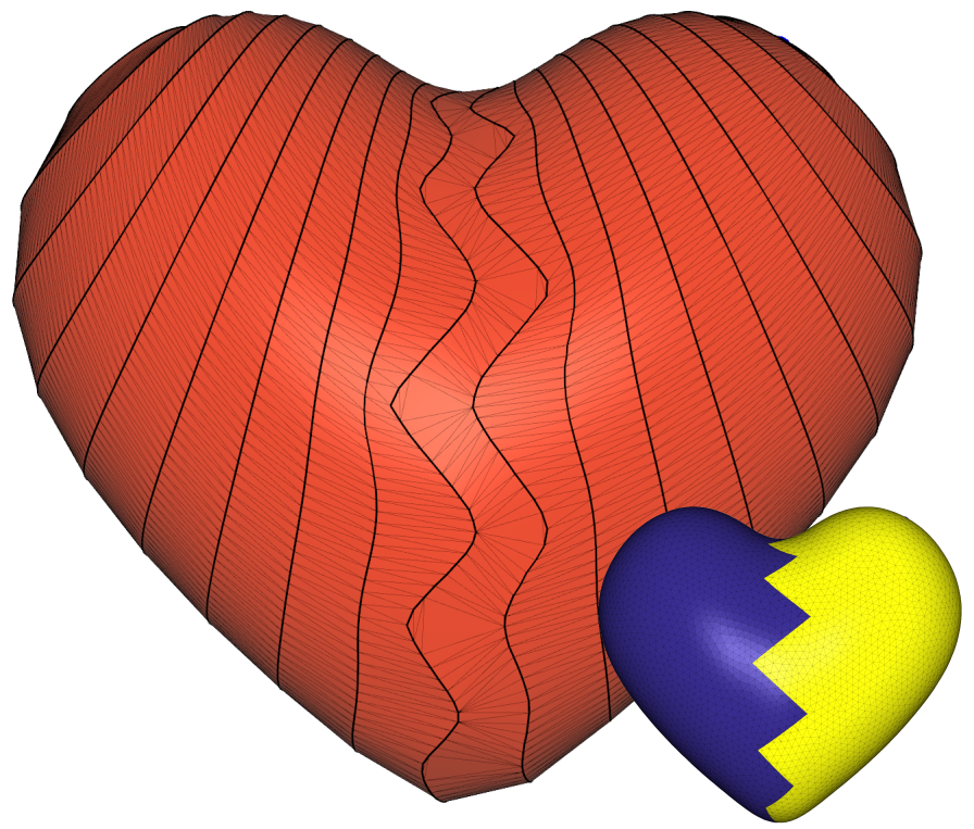
We experimented with our system and created several additional examples. In Fig. 21 we show a heart shape with a nontrivial zig-zag segmentation. In Fig. 22 we show a result obtained on a twisting tube that changes width.
5 Conclusion
We presented an approach for shape representation using a single developable piece of fabric. We show several examples to demonstrate the power and generality of our approach. Currently, we do not attempt to align the zipper curve to the input shape’s features. This means that regions with sharp corners may not be well represented by the assembled ribbon, unless the user manually specifies it. We plan to tackle this issue in the future by using feature detection and incorporating it into the optimization. Additionally, we are interested in targeting more global objectives, such as symmetry. Furthermore, we would like to combine the curve design with the final stage of remeshing to get a developable surface. Currently these steps are strictly decoupled, and we expect to get a better approximation by optimizing both parts simultaneously.
In this paper we mostly discussed the design part of the process, and put less emphasis on the fabrication part. In the future, we plan to explore the possibility of automating the process, extend it to other types of fabrication methods, and search for different applications. One application that we are particularly interested in is pipe cladding, which is part of the process of insulating heated pipes with metal sheets, and is a labour intensive task. The process is similar to our zipping, but usually performed by and expert using a manual approach; our method could be potentially used to greatly simplify this task.
6 Acknowledgements
The authors would like to thank Isabelle von Salis for her support with the fabrication of the prototype. This work was supported in part by the ERC grant iModel (StG-2012-306877).
References
- [\citenameAigerman and Lipman 2015] Aigerman, N., and Lipman, Y. 2015. Orbifold tutte embeddings. ACM Trans. Graph. 34, 6 (Oct.), 190:1–190:12.
- [\citenameBickel et al. 2010] Bickel, B., Bächer, M., Otaduy, M. A., Lee, H. R., Pfister, H., Gross, M., and Matusik, W. 2010. Design and fabrication of materials with desired deformation behavior. ACM Trans. Graph. 29, 4 (July), 63:1–63:10.
- [\citenameBommes et al. 2013] Bommes, D., Lévy, B., Pietroni, N., Puppo, E., Silva, C., Tarini, M., and Zorin, D. 2013. Quad-mesh generation and processing: A survey. Comput. Graph. Forum 32, 6, 51–76.
- [\citenameChandra et al. 2015] Chandra, S., Körner, A., Koronaki, A., Spiteri, R., Amin, R., Kowli, S., and Weinstock, M. 2015. Computing curved-folded tessellations through straight-folding approximation. In Proc. Symposium on Simulation for Architecture & Urban Design.
- [\citenameChen et al. 2014] Chen, X., Zheng, C., Xu, W., and Zhou, K. 2014. An asymptotic numerical method for inverse elastic shape design. ACM Trans. Graph. 33, 4.
- [\citenameEppstein and Gopi 2004] Eppstein, D., and Gopi, M. 2004. Single-strip triangulation of manifolds with arbitrary topology. In Proc. Symp. Computational Geometry, 455–456.
- [\citenameHormann et al. 2007] Hormann, K., Lévy, B., and Sheffer, A. 2007. Mesh parameterization: theory and practice. In ACM SIGGRAPH Courses.
- [\citenameIgarashi and Igarashi 2008] Igarashi, Y., and Igarashi, T. 2008. Pillow: Interactive flattening of a 3D model for plush toy design. In Proc. Smart Graphics.
- [\citenameIgarashi et al. 2009] Igarashi, Y., Igarashi, T., and Suzuki, H. 2009. Interactive cover design considering physical constraints. Comput. Graph. Forum 28, 7, 1965–1973.
- [\citenameJulius et al. 2005] Julius, D., Kraevoy, V., and Sheffer, A. 2005. D-Charts: Quasi-developable mesh segmentation. Comput. Graph. Forum 24, 3, 581–590.
- [\citenameKälberer et al. 2011] Kälberer, F., Nieser, M., and Polthier, K. 2011. Stripe parameterization of tubular surfaces. In Topological Methods in Data Analysis and Visualization. Springer, 13–26.
- [\citenameKilian et al. 2008] Kilian, M., Flöry, S., Chen, Z., Mitra, N. J., Sheffer, A., and Pottmann, H. 2008. Curved folding. ACM Trans. Graph. 27, 3.
- [\citenameKnöppel et al. 2015] Knöppel, F., Crane, K., Pinkall, U., and Schröder, P. 2015. Stripe patterns on surfaces. ACM Trans. Graph. 34, 4.
- [\citenameKolmianič and Guid 2002] Kolmianič, S., and Guid, N. 2002. From geometric modeling to shape modeling. In Proc. Workshop on Geometric Modeling: Fundamentals and Applications, 35–46.
- [\citenameKovalsky et al. 2016] Kovalsky, S. Z., Galun, M., and Lipman, Y. 2016. Accelerated quadratic proxy for geometric optimization. ACM Trans. Graph. 35, 4, 134.
- [\citenameLiu et al. 2009] Liu, Y., Lai, Y., and Hu, S. M. 2009. Stripification of free-form surfaces with global error bounds for developable approximation. IEEE Trans. Automation Science and Engineering 6, 4, 700–709.
- [\citenameLivesu et al. 2017] Livesu, M., Attene, M., Patanè, G., and Spagnuolo, M. 2017. Explicit cylindrical maps for general tubular shapes. Computer-Aided Design. Accepted for publication.
- [\citenameMahdavi-Amiri et al. 2015] Mahdavi-Amiri, A., Whittingham, P., and Samavati, F. 2015. Cover-it: an interactive system for covering 3D prints. In Proc. Graphics Interface, 73–80.
- [\citenameMassarwi et al. 2007] Massarwi, F., Gotsman, C., and Elber, G. 2007. Papercraft models using generalized cylinders. In Proc. Pacific Graphics.
- [\citenameMitani and Suzuki 2004] Mitani, J., and Suzuki, H. 2004. Making papercraft toys from meshes using strip-based approximate unfolding. ACM Trans. Graph. 23, 3, 259–263.
- [\citenameMori and Igarashi 2007] Mori, Y., and Igarashi, T. 2007. Plushie: an interactive design system for plush toys. ACM Trans. Graph. 26, 3.
- [\citenameMyles and Zorin 2012] Myles, A., and Zorin, D. 2012. Global parametrization by incremental flattening. ACM Trans. Graph. 31, 4, 109:1–109:11.
- [\citenameRabinovich et al. 2017] Rabinovich, M., Poranne, R., Panozzo, D., and Sorkine-Hornung, O. 2017. Scalable locally injective mappings. ACM Trans. Graph. 36, 2, 16:1–16:16.
- [\citenameRay et al. 2006] Ray, N., Li, W., Lévy, B., Sheffer, A., and Alliez, P. 2006. Periodic global parameterization. ACM Trans. Graph. 25, 4.
- [\citenameRose et al. 2007] Rose, K., Sheffer, A., Wither, J., Cani, M.-P., and Thibert, B. 2007. Developable surfaces from arbitrary sketched boundaries. In Proc. Symp. Geom. Processing, 163–172.
- [\citenameRossignac 1999] Rossignac, J. 1999. Edgebreaker: Connectivity compression for triangle meshes. IEEE Trans. Vis. Comput. Graph. 5, 1, 47–61.
- [\citenameShatz et al. 2006] Shatz, I., Tal, A., and Leifman, G. 2006. Paper craft models from meshes. The Visual Computer 22, 9-11, 825–834.
- [\citenameShewchuk 1996] Shewchuk, J. R. 1996. Triangle: Engineering a 2D quality mesh generator and Delaunay triangulator. In Applied Computational Geometry: Towards Geometric Engineering, vol. 1148 of Lecture Notes in Computer Science. 203–222.
- [\citenameShtengel et al. 2017] Shtengel, A., Poranne, R., Sorkine-Hornung, O., Kovalsky, S. Z., and Lipman, Y. 2017. Geometric optimization via composite majorization. ACM Trans. Graph. 36, 4 (July), 38:1–38:11.
- [\citenameSkouras et al. 2012] Skouras, M., Thomaszewski, B., Bickel, B., and Gross, M. H. 2012. Computational design of rubber balloons. Comput. Graph. Forum 31, 2, 835–844.
- [\citenameSkouras et al. 2013] Skouras, M., Thomaszewski, B., Coros, S., Bickel, B., and Gross, M. 2013. Computational design of actuated deformable characters. ACM Trans. Graph. 32, 4, 82:1–82:10.
- [\citenameSkouras et al. 2014] Skouras, M., Thomaszewski, B., Kaufmann, P., Garg, A., Bickel, B., Grinspun, E., and Gross, M. H. 2014. Designing inflatable structures. ACM Trans. Graph. 33, 4.
- [\citenameSmith and Schaefer 2015] Smith, J., and Schaefer, S. 2015. Bijective parameterization with free boundaries. ACM Trans. Graph. 34, 4, 70:1–70:9.
- [\citenameStraub and Prautzsch 2011] Straub, R., and Prautzsch, H. 2011. Creating optimized cut-out sheets for paper models from meshes. Tech. rep., Karlsruhe Institute of Technology.
- [\citenameTakahashi et al. 2011] Takahashi, S., Wu, H., Saw, S. H., Lin, C., and Yen, H. 2011. Optimized topological surgery for unfolding 3D meshes. Comput. Graph. Forum 30, 7, 2077–2086.
- [\citenameTang et al. 2016] Tang, C., Bo, P., Wallner, J., and Pottmann, H. 2016. Interactive design of developable surfaces. ACM Trans. Graph. 35, 2, 12:1–12:12.
- [\citenameTarini 2012] Tarini, M. 2012. Cylindrical and toroidal parameterizations without vertex seams. J. Graphics Tools 16, 3, 144–150.
- [\citenameWang 2010] Wang, C. C. L. 2010. From designing products to fabricating them from planar materials. IEEE Computer Graphics and Applications 30, 6, 74–85.
- [\citenameZeng et al. 2012] Zeng, L., Liu, Y., Chen, M., and Yuen, M. M. 2012. Least squares quasi-developable mesh approximation. Computer Aided Geometric Design 29, 7, 565–578.
- [\citenameZhao et al. 2016] Zhao, H., Gu, F., Huang, Q., Galicia, J. A. G., Chen, Y., Tu, C., Benes, B., Zhang, H., Cohen-Or, D., and Chen, B. 2016. Connected Fermat spirals for layered fabrication. ACM Trans. Graph. 35, 4, 100:1–100:10.
- [\citenameZhou et al. 2015] Zhou, Y., Yin, K., Huang, H., Zhang, H., Gong, M., and Cohen-Or, D. 2015. Generalized cylinder decomposition. ACM Trans. Graph. 34, 6, Article 171.
- [\citenamezipit 2017] zipit, 2017. zipit store online. http://www.zipitstore.com/. Accessed: 2017-02-01.