Intercalated Europium Metal in Epitaxial Graphene on SiC
Abstract
X-ray magnetic circular dichroism (XMCD) reveal the magnetic properties of intercalated europium metal under graphene on SiC(0001). Intercalation of Eu nano-clusters (average size 2.5 nm) between graphene and SiC substate are formed by deposition of Eu on epitaxially grown graphene that is subsequently annealed at various temperatures while keeping the integrity of the graphene layer. Using sum-rules analysis of the XMCD of Eu M4,5 edges at K, our samples show paramagnetic-like behavior with distinct anomaly at T 90 K which may be related to the Nèel transition, TN = 91 K, of bulk metal Eu. We find no evidence of ferromagnetism due to EuO or antiferromagnetism due to \ceEu2O3 indicating that the graphene layer protects the intercalated metallic Eu against oxidation over months of exposure to atmospheric environment.
Introduction
In addition to its unique electronic properties and optical transparency, that render it potential applications in spintronics and photovoltaic devicesZhang et al. (2014), graphene has been recognized as the ultimate mono-atomic protective membrane of metal surfaces against corrosionDedkov et al. (2008a, b); Böhm (2014); Bunch et al. (2008). The chemical vapor deposition (CVD) of graphene has by now been established as a scalable method for depositing graphene albeit with inevitable surface defects due to the non-epitaxial nature of the growth that proceeds at multiple points of nucleationHofmann et al. (2015). So, covering weak oxidizing metals (e.g. Ni, Co) with graphene can protect their surfaces over long periods to atmospheric exposureWeatherup et al. (2015), because the metal-oxides formed at defects protect against further oxidation. On the other hand, for strong oxidizers (e.g., Fe or Eu) in atmospheric environment, corrosion through graphene-defects or other protective layers gradually spreads over the whole surface and even penetrates the bulkWeatherup et al. (2015); Anderson et al. (2017a). Defect-free and epitaxial monoatomic layer of graphene has long been produced on SiC(0001) forming a continuous membrane over the whole surface including surface stepsForbeaux et al. (1998). With these advances, modifying the electronic properties of graphene has been investigated either by depositing inert metalsRen et al. (2010); Förster et al. (2012) and metal-oxidesWang et al. (2008) or by intercalating between the graphene and the metal substratePremlal et al. (2009); Schumacher et al. (2014); Voloshina and Dedkov (2014); Huttmann et al. (2017) or between graphene and the SiC buffer-layerSung et al. (2017). Intercalation of metal donors or molecular acceptors into graphite is an old topic that culminated in recipes that enable control of the superstructures (staging phenomena), electrical conduction, superconductivity and even electrical energy storage in batteries (i.e., CF and CLi6)Dresselhaus and Dresselhaus (1981). Thus, intercalation with magnetic metals is a route to modify interfacial magneto-electronic properties with potential applications in spintronics. Here, we report on the magnetic properties of intercalated Eu atoms between graphene and the SiC buffer-layer by employing synchrotron X-ray magnetic circular dichroism (XMCD). We also, report on the chemical stability of the buried Eu layer as the sample is exposed to air over a period of months. Recently, intercalation of Eu between Ir substrate and graphene (prepared by CVD) reveals that the structure and magnetic properties of the intercalated Eu depend on the coverage which does not seem to affect the electronic structureSchumacher et al. (2014). However, a recent study shows that Eu intercalation between graphene and the SiC buffer layer modifies the band of graphene significantlySung et al. (2017). We note that besides the different substrates, the intercalated phases formed in SiCSung et al. (2017) are of higher coverages than those reported on graphene/Ir metalSchumacher et al. (2014).
Samples and Methods
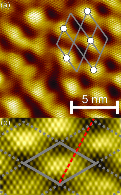
The substrate used in our studies, 6H-SiC(0001) purchased from Cree, Inc., is graphitized in ultra-high vacuum (UHV, Torr) by direct current heating of the sample to 1300 C (measured with an infrared pyrometer). Figure 1b shows a graphene layer with distinct 66 superstructure commonly observed with graphene on SiCForbeaux et al. (1998). Metal intercalation is achieved by initial deposition of nominal several monolayers of Eu metal on a SiC supported graphene (see Fig. 1c) followed by annealing, leading to two competing processes namely, intercalation/diffusion of metal atoms through the graphene sheet and atom desorption from the graphene surface into the vacuum (see illustration in Fig. 1a). Slow step-wise annealing up to the metal desorption temperature provides conditions preferred for intercalation. After complete atom desorption, STM images show an undamaged graphene surface but with bright spots due to Eu clusters that are situated at the vertices of the 66 superstructure (Fig. 1d-e, Fig. 2, and in the SISI-EU ). The high-resolution STM images (Fig. 2) confirm that clusters are formed beneath the graphene, and that the cluster superstructure is rotated 30∘ with respect to the graphene. Under further prolonged annealing up to 1200 C, Eu atoms de-intercalate and the initial graphene interface can be restored. This indicates that the density of an intercalated metal can be controlled in intercalation/de-intercalation cycling. We note that lower annealing temperatures has been reported in the Ref. Sung et al. (2017) (120 C), confining the Eu diffusion between graphene and buffer layer, whereas annealing at 300 C shifts the Eu between the buffer and SiC and transforms the graphene to a bilayer. The annealing temperatures are higher in the current study resulting in a self-organized network of clusters of 25 atoms separated by at least 1.8 nm which behave independently in their magnetic response.
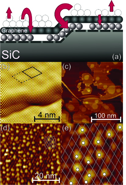
The location of the intercalated metal whether between graphene and buffer layer or between buffer layer and SiC is an outstanding question. The metal position depends on the preparation conditions and dramatically affects the properties of the intercalated system. The use of high temperatures in the current study (800 C) desorbs most of the deposited Eu and generates the cluster phase. Other phases are possible in the system for lower annealing temperatures. A similar cluster phase has also been observed for intercalated Au in graphene on SiC achieved at relatively high temperatures 700 CNarayanan Nair et al. (2016). The Au cluster position is also defined by the 66 supercell with average separation between the clusters 2.2 nm. Moreover, this study suggests that, the Au or Eu formed clusters between the buffer layer and graphene, not only explain the preference of nucleation to be at the vertices of the 66 supercell but also that the cluster phase is a more general phenomenon of metal intercalation into graphene-SiC.
XMCD measurements are performed at the 4-ID-C beamline at the Advanced Photon Source (Argonne National Laboratory) in a chamber equipped with a high magnetic field ( T) produced by a split-coil superconducting magnet. Field dependence of the XMCD spectra are collected in helicity-switching mode in external magnetic fields applied parallel to the incident x-ray wave vector at energies that cover the Eu (1158 eV) and (1127 eV) binding energies. Measurements of x-ray absorption spectroscopy (XAS) signals are collected by total electron yield (TEY). For data analysis and normalization, the individual XAS, and , are normalized by their respective monitors to compensate for incident-beam intensity variations. For the initial background subtraction, the XAS ( and ) has a flat value subtracted such that the lowest energy (i.e. sufficiently far from the edge) is at 0 intensity, removing both background and offsets due to the beam. The total XAS () is then scaled by a factor such that its maximum intensity is 1. That scale factor is then used to also scale the individual ( and ) XAS. The XMCD signal is obtained from the difference between two XAS spectra of the left- and right-handed helicities, and . More details on data reduction is provided elsewhereAnderson et al. (2017b). We note that our intercalated samples are removed from the ultra-high vacuum chamber and transported in air for the XMCD experiments. As we discuss below and in the SISI-EU , we have also tested the samples after exposure of 9 months in air.
Results and Discussion
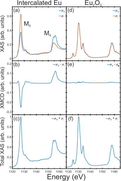
Figure 3 shows the XAS, XMCD, and total XAS at the Eu and edges at K and T for intercalated Eu (left) and for \ceEu2O3 (right). We measure \ceEu2O3 as a control to monitor possible oxidation of our sample as it is exposed to air. Each of the three signals shows a significant contrast between the two samples. Figures 3a and 3d show the XAS of the intercalated Eu and \ceEu2O3 with the latter exhibiting noticeable splitting of the peak, which has been documented as corresponding to Eu3+ Thole et al. (1985); Mizumaki et al. (2005). However, the intercalated Eu has a very prominent difference between the and while the \ceEu2O3 has almost none. This leads to a strong XMCD signal for the intercalated (Fig. 3b) but to nearly flat XMCD signal for the oxide (Fig. 3e). The zero XMCD signal for \ceEu2O3 is expected for the non-magnetic Eu3+ where and a total moment Concas et al. (2011).
The XMCD of the intercalated Eu enables to quantitatively determine the orbital, , and spin, , contributions to the total moment, , of Eu2+ via sum rules derived by Carra et. al.Carra et al. (1993) as follows:
| (1) |
and
| (2) |
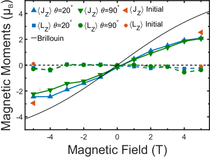
where , , , and is the number of electron holes in the valence shell ( for Eu2+) (it should be noted that our definition for differs from the used in Ref. (14)). In Eq. 2, the term vanishes due to the zero orbital moment. We note that a strong spin moment, , and nearly zero orbital moment, , are consistent with Hund’s rules for Eu2+ ()Schumacher et al. (2014); Carra et al. (1993); Crocombette et al. (1996); Wu and Freeman (1994) and thus . Figure 4 shows moment calculations at K as a function of magnetic field from +5 T to -5 T. Scans are conducted at both 20∘ and 90∘ angle between the magnetic field direction and the surface showing nearly paramagnetic-like behavior with no evidence of magnetic anisotropy. The dependence of the moment on magnetic field shown in Fig. 4 is similar in shape to the Brillouin function (solid line) but with smaller moment than that expected for paramagnetic Eu2+. That the magnetic moment does not saturate at finite fields is another indication of no strong collective behavior of intercalated Eu clusters under graphene. The fact that the magnetic moment is well below its saturation value 7, at high field and at the low temperature K, is puzzling.
We emphasize that the XMCD unequivocally determines the electronic configuration of the intercalant as Eu2+, as expected for metal Eu but also for ferromagnetic EuO. Indeed, previous XAS measurements of Eu metal and EuO are almost indistinguishable due to the core levels, involved in the transitions, that are hardly influenced by the specific chemistry of the elementThole et al. (1985). However, detailed comparison of our XMCD with that of thin films EuO indicate differences that point to the fact that the intercalated Eu is in its metallic state. Also, the magnetic ground states of the metal and oxide are distinct at low temperatures. Whereas EuO is ferromagnetic at TC KWachter (1972); Lettieri et al. (2003) with finite hysteresisLettieri et al. (2003); Wäckerlin et al. (2015), Eu metal undergoes an incommensurate helical magnetic structure at T KNereson et al. (1964); Jensen and Mackintosh (1991). As shown in Fig. 4 there is no evidence of magnetic moment saturation or anisotropy that is expected from a ferromagnet ruling out the possibility that the intercalated Eu is an oxide (i.e., EuO). Another possibility is that intercalated Eu under graphene adopts the R superstructure as an intercalated Eu in highly pyrolytic graphite (HOPG) crystals, namely, \ceC6EuSuematsu et al. (1983). However, magnetization and specific heat of \ceC6Eu indicate it becomes antiferromagnetic (AFM) at about 40 K. This scenario can also be discarded since AFM systems do not yield XMCD signals, and we do observe a strong XMCD signal below 40 K in our samples.
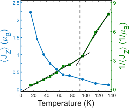
To further explore the magnetic properties of the intercalated Eu nano-clusters, we have collected XMCD spectra at the regime (from 1120 to 1140 eV) at various temperatures and at fixed T. As discussed in the SISI-EU , because for Eu2+, measuring the XMCD on either the M5 or M4 is sufficient to determine the magnetic moment. Figure 5 shows the temperature dependence of from the XMCD spectra for the M5 as a function of temperature, with characteristic increase common to a paramagnetic system. However, the 1/ of the same data shows two distinct regions that overlaid by linear fits (dashed lines) intersect at K. We note that is very close to the the Nèel temperature, , of bulk metallic Eu at 91 K (vertical dashed line in Fig. 5)Nereson et al. (1964); Jensen and Mackintosh (1991). As mentioned previously, the Curie temperature of EuO is at K, which is substantially lower than the anomaly observed in our temperature dependenceWachter (1972); Lettieri et al. (2003). This is yet another indication that the intercalated Eu-clusters under graphene are likely in their metallic structure. In the SI we propose three scenarios of possible layers underneath graphene that may also explain the finite clustering size nm in diameter.
Conclusions
In conclusion, we have succeeded to intercalate Eu under epitaxial graphene on SiC buffer layer. Our XMCD results show the electronic configuration of the intercalant is that of Eu2+ likely in its metallic state or as a Eu-silicideAveryanov et al. (2016). Our STM images show that the Eu forms relatively uniform nano-clusters of approximately 2.5 nm in diameter, and although the clusters are randomly distributed they preferably nucleate at the vertices of the 66 super structure of graphene on SiC which act as nucleation centers. We argue that unlike intercalated \ceC6Eu, the Eu under graphene forms clusters that likely conform to the square unit cell of metallic Eu and that, due to the incommensurabilty between graphene and the Eu, the clusters are limited in size. The temperature dependence of at fixed magnetic field T is consistent with the paramagnetic behavior displayed in the magnetic field dependence at K, namely, no anisotropy or hysteresis effects are observed. Although Eu is a highly oxidizing metal in air, the epitaxial graphene layer formed on SiC is practically defect free that protects the intercalated Eu against oxidation under atmospheric conditions over periods of months.
I Acknowledgments
Ames Laboratory is operated by Iowa State University by support from the U.S. Department of Energy, Office of Basic Energy Sciences, under Contract No. DE-AC02-07CH11358. Use of the Advanced Photon Source, an Office of Science User Facility operated for the U.S. Department of Energy (DOE) Office of Science by Argonne National Laboratory, is supported by the U.S. DOE under Contract No. DE-AC02-06CH11357.
References
- Zhang et al. (2014) X. Zhang, B. R. S. Rajaraman, H. Liu, and S. Ramakrishna, “Graphene’s potential in materials science and engineering,” RSC Adv. 4, 28987 (2014).
- Dedkov et al. (2008a) Y. S. Dedkov, M. Fonin, and C. Laubschat, “A possible source of spin-polarized electrons: The inert graphene/Ni(111) system,” Appl. Phys. Lett. 92, 052506 (2008a).
- Dedkov et al. (2008b) Y. S. Dedkov, M. Fonin, U. Rüdiger, and C. Laubschat, “Graphene-protected iron layer on Ni(111),” Appl. Phys. Lett. 93, 022509 (2008b).
- Böhm (2014) S. Böhm, “Graphene against corrosion,” Nat. Nanotech. 9, 741 (2014).
- Bunch et al. (2008) J. S. Bunch, S. S. Verbridge, J. S. Alden, A. M. van der Zande, J. M. Parpia, H. G. Craighead, and P. L. McEuen, “Impermeable Atomic Membranes from Graphene Sheets,” Nano Lett. 8, 2458 (2008).
- Hofmann et al. (2015) S. Hofmann, P. Braeuninger-Weimer, and R. S. Weatherup, “CVD-Enabled Graphene Manufacture and Technology,” J. Phys. Chem. Lett. 6, 2714 (2015).
- Weatherup et al. (2015) R. S. Weatherup, L. D’Arsié, A. Cabrero-Vilatela, S. Caneva, R. Blume, J. Robertson, R. Schloegl, and S. Hofmann, “Long-Term Passivation of Strongly Interacting Metals with Single-Layer Graphene,” J. Am. Chem. Soc. 137, 14358 (2015).
- Anderson et al. (2017a) N. A. Anderson, Q. Zhang, M. Hupalo, R. A. Rosenberg, M. C. Tringides, and D. Vaknin, “Magnetite nano-islands on silicon-carbide with graphene,” J. Appl. Phys. 121, 014310 (2017a).
- Forbeaux et al. (1998) I. Forbeaux, J.-M. Themlin, and J.-M. Debever, “Heteroepitaxial graphite on 6H-SiC(0001): Interface formation through conduction-band electronic structure,” Phys. Rev. B 58, 16396 (1998).
- Ren et al. (2010) Y. Ren, S. Chen, W. Cai, Y. Zhu, C. Zhu, and R. S. Ruoff, “Controlling the electrical transport properties of graphene by in situ metal deposition,” Appl. Phys. Lett. 97, 053107 (2010).
- Förster et al. (2012) D. F. Förster, T. O. Wehling, S. Schumacher, A. Rosch, and T. Michely, “Phase coexistence of clusters and islands: Europium on graphene,” New J. Phys. 14, 023022 (2012).
- Wang et al. (2008) X. Wang, S. M. Tabakman, and H. Dai, “Atomic Layer Deposition of Metal Oxides on Pristine and Functionalized Graphene,” J. Am. Chem. Soc. 130, 8152 (2008).
- Premlal et al. (2009) B. Premlal, M. Cranney, F. Vonau, D. Aubel, D. Casterman, M. M. D. Souza, and L. Simon, “Surface intercalation of gold underneath a graphene monolayer on SiC(0001) studied by scanning tunneling microscopy and spectroscopy,” Appl. Phys. Lett. 94, 263115 (2009).
- Schumacher et al. (2014) S. Schumacher, F. Huttmann, M. Petrović, C. Witt, D. F. Förster, C. Vo-Van, J. Coraux, A. J. Martínez-Galera, V. Sessi, I. Vergara, R. Rückamp, M. Grüninger, N. Schleheck, F. Meyer zu Heringdorf, P. Ohresser, M. Kralj, T. O. Wehling, and T. Michely, “Europium underneath graphene on Ir(111): Intercalation mechanism, magnetism, and band structure,” Phys. Rev. B 90, 235437 (2014).
- Voloshina and Dedkov (2014) E. N. Voloshina and Y. S. Dedkov, “Electronic and magnetic properties of the graphene/Eu/Ni(111) hybrid system,” Z. Naturforsch. A 69, 297 (2014), arXiv:1407.4389 .
- Huttmann et al. (2017) F. Huttmann, D. Klar, N. Atodiresei, C. Schmitz-Antoniak, A. Smekhova, A. J. Martínez-Galera, V. Caciuc, G. Bihlmayer, S. Blügel, T. Michely, and H. Wende, “Magnetism in a graphene-4f-3d hybrid system,” Phys. Rev. B 95, 075427 (2017).
- Sung et al. (2017) S. Sung, S. Kim, P. Lee, J. Kim, M. Ryu, H. Park, K. Kim, B. I. Min, and J. Chung, “Observation of variable hybridized-band gaps in Eu-intercalated graphene,” Nanotechnology 28, 205201 (2017).
- Dresselhaus and Dresselhaus (1981) M. S. Dresselhaus and G. Dresselhaus, “Intercalation compounds of graphite,” Adv. Phys. 30, 139 (1981).
- (19) See Supplementary Material at (link) for more information on the sample preparation and details on the intercalation, sample exposure to air over time as measured by XMCD, details on the calculation of the magnetic moment from the XMCD, more details on the Eu clusters under graphene and the relationship to graphite intercalation compounds, and examination of various hypotheses regarding metal-Eu plane mismatch with graphene as a mechanism to rationalize nucleation and finite average size of the Eu clusters under graphene.
- Narayanan Nair et al. (2016) M. Narayanan Nair, M. Cranney, T. Jiang, S. Hajjar-Garreau, D. Aubel, F. Vonau, A. Florentin, E. Denys, M.-L. Bocquet, and L. Simon, “Noble-metal intercalation process leading to a protected adatom in a graphene hollow site,” Phys. Rev. B 94, 075427 (2016).
- Anderson et al. (2017b) N. A. Anderson, Q. Zhang, M. Hupalo, R. A. Rosenberg, J. W. Freeland, M. C. Tringides, and D. Vaknin, “Magnetic properties of Dy nano-islands on graphene,” J. Magn. Magn. Mater. 435, 212 (2017b).
- Thole et al. (1985) B. T. Thole, G. van der Laan, J. C. Fuggle, G. A. Sawatzky, R. C. Karnatak, and J.-M. Esteva, “3d x-ray-absorption lines and the 3d94fn+1 multiplets of the lanthanides,” Phys. Rev. B 32, 5107 (1985).
- Mizumaki et al. (2005) M. Mizumaki, T. Uozumi, A. Agui, N. Kawamura, and M. Nakazawa, “Admixture of excited states and ground states of a Eu3+ ion in \ceEu3Fe5O12 by means of magnetic circular dichroism,” Phys. Rev. B 71, 134416 (2005).
- Concas et al. (2011) G. Concas, J. K. Dewhurst, A. Sanna, S. Sharma, and S. Massidda, “Anisotropic exchange interaction between nonmagnetic europium cations in \ceEu2O3,” Phys. Rev. B 84, 014427 (2011).
- Carra et al. (1993) P. Carra, B. T. Thole, M. Altarelli, and X. Wang, “X-ray circular dichroism and local magnetic fields,” Phys. Rev. Lett. 70, 694 (1993).
- Crocombette et al. (1996) J. P. Crocombette, B. T. Thole, and F. Jollet, “The importance of the magnetic dipole term in magneto-circular x-ray absorption dichroism for 3d transition metal compounds,” J. Phys.: Condens. Matter 8, 4095 (1996).
- Wu and Freeman (1994) R. Wu and A. J. Freeman, “Limitation of the Magnetic-Circular-Dichroism Spin Sum Rule for Transition Metals and Importance of the Magnetic Dipole Term,” Phys. Rev. Lett. 73, 1994 (1994).
- Wachter (1972) P. Wachter, “The optical electrical and magnetic properties of the europium chalcogenides and the rare earth pnictides,” C R C Crit. Rev. Solid State Sci. 3, 189 (1972).
- Lettieri et al. (2003) J. Lettieri, V. Vaithyanathan, S. K. Eah, J. Stephens, V. Sih, D. D. Awschalom, J. Levy, and D. G. Schlom, “Epitaxial growth and magnetic properties of EuO on (001) Si by molecular-beam epitaxy,” Appl. Phys. Lett. 83, 975 (2003).
- Wäckerlin et al. (2015) C. Wäckerlin, F. Donati, A. Singha, R. Baltic, A.-C. Uldry, B. Delley, S. Rusponi, and J. Dreiser, “Strong antiferromagnetic exchange between manganese phthalocyanine and ferromagnetic europium oxide,” Chem. Commun. 51, 12958 (2015).
- Nereson et al. (1964) N. G. Nereson, C. E. Olsen, and G. P. Arnold, “Magnetic Structure of Europium,” Phys. Rev. 135, A176 (1964).
- Jensen and Mackintosh (1991) J. Jensen and A. R. Mackintosh, Rare Earth Magnetism (Clarendon Oxford, 1991).
- Suematsu et al. (1983) H. Suematsu, K. Ohmatsu, T. Sakakibara, M. Date, and M. Suzuki, “Magnetic properties of europium-graphite intercalation compound C6Eu,” Synth. Met. 8, 23 (1983).
- Averyanov et al. (2016) D. V. Averyanov, A. M. Tokmachev, C. G. Karateeva, I. A. Karateev, E. F. Lobanovich, G. V. Prutskov, O. E. Parfenov, A. N. Taldenkov, A. L. Vasiliev, and V. G. Storchak, “Europium Silicide – a Prospective Material for Contacts with Silicon,” Sci Rep 6, 25980 (2016).