Transmission magnitude and phase control for polarization-preserving reflectionless metasurfaces
Abstract
For transmissive applications of electromagnetic metasurfaces, an array of subwavelength Huygens’ meta-atoms are typically used to eliminate reflection and achieve a high transmission power efficiency together with a wide transmission phase coverage. We show that the underlying principle of low reflection and full control over transmission is asymmetric scattering into the specular reflection and transmission directions that results from a superposition of symmetric and anti-symmetric scattering components, with Huygens’ meta-atoms being one example configuration. Available for oblique illumination in TM polarization, a meta-atom configuration comprising normal and tangential electric polarizations is presented, which is capable of reflectionless, full-power transmission and a transmission phase coverage as well as full absorption. For lossy metasurfaces, we show that a complete phase coverage is still available for reflectionless designs for any value of absorptance. Numerical examples in the microwave and optical regimes are provided.
I Introduction
Presented as two-dimensional equivalents of volumetric metamaterials Holloway et al. (2012), metasurfaces have attracted a significant interest in recent years. Metasurfaces are typically realized as a doubly periodic array of small polarizable particles over a subwavelength thickness. With a distinct advantage of low loss over volumetric metamaterials, a wide range of novel reflection, transmission, and absorption applications ranging from microwave to optical frequencies have been reported Kildishev et al. (2013); Yu and Capasso (2014); Meinzer et al. (2014); Glybovski et al. (2016); Chen et al. (2016).
There are a host of metasurface applications in the transmission mode. Based on the phased array antenna principle Hansen (2009) and the generalized law of refraction Yu et al. (2011), a linear gradient of transmission phase imparted on the transmitted wave can bend an incident beam or plane wave in an anomalous direction Pfeiffer and Grbic (2013a); Aieta et al. (2012a); Pfeiffer et al. (2014); Yu et al. (2015). A flat focusing lens is obtained by spatially nonlinear transmission phase distributions Monticone et al. (2013); Lin et al. (2014); Wang et al. (2015); Khorasaninejad et al. (2016). Local modulation of transmission amplitude and/or phase leads to holograms Ni et al. (2013); Huang et al. (2013); Arbabi et al. (2015). As polarization transformers, thin metasurfaces can replace electrically thick wave plates by assigning distinct transmission phases to two orthogonal polarization components Zhao et al. (2012); Pfeiffer and Grbic (2013b); Grady et al. (2013).
A high transmission magnitude toward unity and a wide transmission phase range toward are highly desirable for high-efficiency operation of transmitted wave shaping. At optical frequencies, a single layer of plasmonic or dielectric resonant particles are commonly adopted for transmissive metasurfaces, owing to relative ease of fabrication. It was recognized that an infinitesimally thin layer of electrically polarizable particles support a complete range for the cross-polarized transmission phase, but not for the co-polarized transmission. Accordingly, formalization of the generalized laws of reflection and refraction as well as their experimental demonstrations were performed for the cross-polarized components scattered by -shaped optical antennas under linearly polarized illuminations Yu et al. (2011); Aieta et al. (2012b), albeit at a low cross-polarized transmission efficiency. It was later revealed that the maximum cross-coupled power efficiency is 25% Monticone et al. (2013). Another approach to achieve a transmission phase coverage is to exploit the Pancharatnam-Berry phase together with circularly polarized illuminations. For the transmitted circularly polarized wave of the opposite handedness, the phase can be adjusted simply by rotating the principal axes of a wave-plate element Lin et al. (2014); Zheng et al. (2015); Huang et al. (2013). Still, this approach involves cross-polarized transmitted waves and a completely reflectionless operation is not possible.
For polarization-preserving applications to date, reflectionless metasurfaces with a complete transmission phase coverage are based on Huygens’ meta-atoms Pfeiffer and Grbic (2013a); Yu et al. (2015); Shalaev et al. (2015); Decker et al. (2015); Chong et al. (2016). A Huygens’ meta-atom is designed such that an orthogonal set of tangential electric and magnetic dipole moments are induced upon external plane-wave excitation. When the two induced dipoles satisfy a balanced condition, full transmission and zero reflection can be obtained for lossless cases with the transmission phase that can be designed to have any value within a complete range. In the microwave regime, short conductor traces are typically used for electric dipoles. For equivalent magnetic dipoles, either metallic ring resonators Pfeiffer and Grbic (2013a) or conductor traces in a multi-layer dielectric substrate Pfeiffer and Grbic (2013b); Wong et al. (2015); Epstein and Eleftheriades (2016) are utilized. Utilizing a combination of continuous and discrete printed multi-layer conductor traces for realizing Huygens’ meta-atoms, microwave transmissive metamaterials for lenses, beam deflectors, and vortex beam generators with efficiencies as high as 91% have been demonstrated Cai et al. (2017a); Luo et al. (2017); Cai et al. (2017b). In the optics regime, a dielectric resonator meta-atom can be designed to support both electric and equivalent magnetic polarization currents at the same wavelength Decker et al. (2015); Yu et al. (2015); Shalaev et al. (2015). It is challenging to design induced electric and magnetic polarizations to satisfy a balanced amplitude and phase relation at the same frequency due to strong mutual coupling between them. Furthermore, the bandwidth of the magnetic resonance tends to be narrower than that of the electric one. At microwave frequencies, the length and shape of a thin conductor wire may be designed to strike a balance between the induced electric and equivalent magnetic dipole moments. This approach has been demonstrated with a circularly polarized Huygens spiral particle in Niemi et al. (2013).
In this paper, a fundamental principle behind full power transmission with a complete phase coverage is investigated for polarization-preserving metasurfaces. It is shown that generation of an anti-symmetric scattering component by the induced polarizations and its destructive interference with the symmetric scattering component in nullifying the total reflected wave is the key design principle. In Huygens’ metasurfaces, a tangential magnetic dipole moment provides the necessary anti-symmetric scattering. However, it is not the only possible source of anti-symmetric scattering. It has been recently shown that the effect of a tangential magnetic polarization can be equivalently generated by a spatially varying normal electric polarization Albooyeh et al. (2017). Taking advantage of this equivalence, a meta-atom configuration comprising entirely of electric dipole moments that is capable of full transmission with a phase coverage is presented. The new reflectionless metasurface configuration is available for oblique illuminations in the TM polarization. Here, the anti-symmetric scattering is provided by an electric dipole that is polarized normal to the metasurface.
When a combination of tangential and normal induced electric dipoles are realized with a tilted electric dipole meta-atom, the identical frequency dispersion of the two orthogonal dipole moments permits dispersionless full transmission at a fixed oblique incidence angle. Furthermore, the resonance of a dipole meta-atom can be tuned in order to achieve a full transmission phase coverage. It is known that metallic gratings having an array of narrow slits or apertures allow dispersionless broadband extraordinary transmission under a TM-polarized illumination at some fixed oblique angle Huang et al. (2010); Alù et al. (2011); Fan et al. (2012). The underlying physics of this broadband full transmission is an impedance match between an oblique TM-polarized illumination and a propagating mode inside a slit Alù et al. (2011). In contrast, the dispersionless transmission property of a tilted dipole array in this study is of geometrical nature of the dipole pattern null directions. This allows the frequency dispersion of a dipole meta-atom to be exploited for transmission phase synthesis.
Furthermore, the inevitable effect of absorption in practical metasurface realizations on the transmission phase coverage is discussed. It is revealed that a complete range of transmission coverage is still available regardless of the amount of loss for reflectionless designs. Finally, illustrative uniform metasurface design examples are provided and analyzed. As a microwave example, a tilted thin conducting strip dipole array is shown for providing full transmission and a complete phase coverage. As its lossy variant, an impedance-loaded strip dipole array is analyzed for full phase coverage as well as for perfect absorption. For an example in the optical regime, high transmission and full phase coverage by an all-dielectric metasurface composed of dielectric bars of rectangular cross section are demonstrated.
In the following time-harmonic analysis at an angular frequency , an time dependence is assumed and suppressed.
II TM-mode reflection and transmission
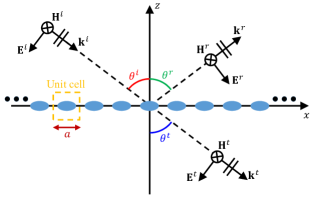
We treat a uniform (non-gradient), single-layer metasurface in free space. As will be shown, lossless metasurfaces supporting electric polarizations only are capable of full-power transmission in the TM polarization. Figure 1 illustrates a planar metasurface in the -plane illuminated by a TM-polarized plane wave propagating in the -plane with an angle of incidence . The unit-cell dimensions are and in the - and -axis directions, respectively. The dimensions are set such that only the fundamental Floquet mode fields propagates away from the metasurface. Away from the metasurface where all evanescent higher-order Floquet mode waves vanish, the incident, reflected, and transmitted electric fields can be written as
| (1) |
where the superscripts ‘i,’ ‘r,’ and ‘t’ denote the incident, reflected, and transmitted fields, respectively, and denotes the corresponding E-field vector amplitude. The associated wave vectors in the -plane are given by , , and , with denoting the free-space wavenumber. All magnetic fields are -polarized. For a uniform metasurface, all three angles are the same .
For metasurfaces that do not scatter cross-polarized fields, the transmission and reflection in Fig. 1 can be described using a two-port network in terms of -parameters, with plane-wave ports 1 and 2 defined in positive- and negative- half spaces. With the phase reference planes for both ports set to , the reflection coefficient and the transmission coefficient are defined as the ratios of tangential E-field amplitudes as
| (2) |
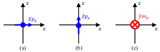
There are three elemental dipole meta-atoms that scatter TM-polarized fields, which are assumed to be excited by the incident wave. They are two orthogonal electric dipoles in the plane of incidence (the -plane) and one magnetic dipole that is directed normal to the plane of incidence, as shown in Fig. 2. Each point dipole is positioned at the coordinate origin. A general meta-atom can be represented as a superposition of these three dipoles. The scattering characteristics of the elemental dipoles are discussed next.
II.1 Symmetric scattering
A planar array of the tangential electric dipole in Fig. 2(a) radiates plane waves symmetrically into . The scattered E-field amplitudes, and , in the reflection and transmission directions, respectively, are given by
| (3) | |||||
| (4) |
where is the free-space intrinsic impedance and represents the unit-cell area in the -plane. Also, and are the unit vectors in their respective propagation directions. The tangential components of and are the same (symmetric). Denoting this value by , we find
| (5) |
These scattered field amplitudes could be cast in terms of the surface-averaged electric polarization current density .
II.2 Anti-symmetric scattering
Both a normal electric dipole [Fig. 2(b)] and a tangential magnetic dipole [Fig. 2(c)] radiate anti-symmetrically into . First, the -directed electric dipole meta-atom generates scattered plane waves in the , directions with the E-field amplitudes given by
| (6) | |||||
| (7) |
The -components of these two vectors are different by sign (anti-symmetric). Denoting the anti-symmetric component by , we find
| (8) |
Next, a planar array of the -directed magnetic dipole meta-atom in Fig. 2(c) creates the E-field amplitudes for the scattered plane waves given by
| (9) | |||||
| (10) |
The anti-symmetric -components can be written as
| (11) |
The field amplitudes can also be written in terms of the surface-averaged polarization current densities, and .
II.3 Transmission and reflection coefficients for total fields
Infinitely thin metasurfaces can support tangential electric polarizations only and the resulting symmetric scattering is the reason for low transmission power efficiencies for polarization-preserving designs Monticone et al. (2013). For Huygens’ metasurfaces, the asymmetric scattering enabled by a combination of orthogonally directed tangential electric and magnetic dipoles allows full transmission Yu et al. (2015); Decker et al. (2015). In order to support an equivalent magnetic dipole realized using a circulating electric polarization, a Huygens’ metasurface cannot have a vanishingly small thickness.
We note that the anti-symmetric scattering may be provided by a normal electric dipole rather than a tangential magnetic dipole. Regardless of the origin of anti-symmetric radiation, the total tangential E-field components for the reflected and transmitted waves can be written as a superposition as
| (12) |
where the symmetric component is given by (5). The anti-symmetric component is given by (8) if is used and by (11) if is used. Then, we can write the reflection and transmission coefficients as
| (13) | |||||
| (14) |
where and represent reflection coefficients for the symmetric and anti-symmetric components, respectively. In (14), denotes the transmission coefficient in the absence of anti-symmetric scattering.
III Transmission phase for lossless, reflectionless metasurfaces
For lossless metasurfaces, power conservation requires . In terms of and , this condition translates into
| (15) |
Now, we require a reflectionless operation for maximum power transmission , or set . Using this condition in (15), we obtain , which can be rewritten as
| (16) |
if we write (i.e, ). Using (16), the total transmission coefficient is found to be
| (17) |
Hence, we find
| (18) |
Starting from instead, a similar analysis finds
| (19) |
where . From (18)–(19), we find that the transmission phase range is twice those of the transmission and reflection coefficients of the symmetric component. The magnitude of the transmission coefficient is unity due to full transmission, as it should be for lossless, reflectionless metasurfaces.
Let us assume no bianisotropy and a standard Lorentz frequency dispersion for the lossless electric polarizability for the horizontal electric dipole . The polarizability can be modeled as Bohren and Huffman (2004); Asadchy et al. (2015)
| (20) |
where is the resonance strength coefficient related to the plasma frequency and is the electric resonance frequency. The polarizability relates the induced dipole moment to the local excitation field at the dipole location. By defining an effective polarizability for the dipole in an array environment, the induced dipole moment can be written relative to the incident field as . It is known that the two polarizabilities are related by Asadchy et al. (2015)
| (21) |
in the TM polarization. Using (5), (20), and (21), the expression for is found to be
| (22) |
At a design frequency , the phase of can be adjusted to any value in the range or by adjusting , , and of a resonant meta-atom. From (19), it can be seen has a full range.
It is instructive to inspect the physical conditions for zero reflection in terms of dipole moments. For a combination of and , setting using (5) and (11) gives
| (23) |
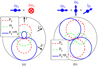
In Paniagua-Domínguez et al. (2016), extended relations of (23) between the electric and magnetic dipole amplitudes for a generalized Brewster effect in dielectric metasurfaces were derived for any given incidence angle, frequency, and polarization. For normal incidence , (23) corresponds to a zero backscattering condition (in the -axis direction). This condition for an orthogonal set of electric and magnetic dipoles has also been utilized in antenna designs Green (1966); Jin and Ziolkowski (2010). In the case of planar array or metasurface designs, zero specular reflection is of interest and (23) is the necessary condition at any incidence angle. In Ra’di et al. (2015), the same balance condition was the principle behind thin Huygens sheet absorbers under a normal incidence. As an example, the element (meta-atom) scattering pattern of a balanced electric-magnetic dipole pair for a 60° incidence case is shown in Fig. 3(a). Together with the total pattern, the individual scattering patterns of and are also shown. In the specular reflection direction, the two individual patterns destructively interfere to create a null, while they interfere constructively in the transmission direction. The phases of the two moments and may be varied under the condition (23) to tune the transmission phase.
For a combination of and , the zero reflection condition translates to
| (24) |
Hence, the two orthogonal induced dipole components should be in phase and their magnitudes should scale properly as a function of . The individual and total scattering patterns for a combination of two electric dipoles satisfying (24) are shown in Fig. 3(b) for the same 60° oblique illumination. A destructive interference creates a scattering null in the direction. As indicated in Fig. 3(b), this combination of two orthogonal dipoles corresponds to a single tilted electric dipole. Hence, there exists an interesting realization strategy in microwaves, where the direction of a low-loss conduction current can be accurately controlled by shaping thin conductors in meta-atoms. Using a tilted straight dipole meta-atom to realize in Fig. 3(b), (24) will be satisfied for any value of . The tangential and normal dipole moments will follow exactly the same frequency dispersion. The result is dispersionless zero reflection at the specific oblique incidence angle that matches the dipole tilt angle in the opposite direction. For lossless meta-atoms, this translates into dispersionless full transmission. When volumetric electric polarization currents are utilized, and should be jointly designed to satisfy the proper magnitude and phase relations, i.e., (24). A microwave metasurface design based on the former strategy and an optical design based on the latter approach are presented in Sec. V.
It is stressed that using tangential and normal electric dipoles for creating reflectionless metasurfaces is limited to oblique illuminations in the TM polarization. At a normal incidence, the reflection direction is also normal to the surface. Even if the normal electric dipole, , is induced by the incident wave, it cannot scatter in the reflection and transmission directions, which are the axial directions of . In comparison, the combination of tangential electric and magnetic dipoles is available for any angle of incidence.
Since either a tangential magnetic dipole or a normal electric dipole can contribute to creating zero reflection together with a given tangential electric dipole, we can find a relation between and for contributing the same effect. By equating the values of due to the two dipoles from (8) and (11), we find , which can be written in the form
| (25) |
in terms of surface-averaged polarizations. Here, is the free-space permittivity and , represent the unit surface normal and the tangential wave vector, respectively. Identified in Albooyeh et al. (2017), (25) represents an equivalence between a tangential magnetic polarization and a spatially-varying normal electric polarization.
IV Transmission magnitude and phase for lossy, reflectionless metasurfaces
Absorption in lossy constituent materials is inevitable in practical realizations, resulting in reduction of the transmission power efficiency from 100%. On the other hand, zero reflection and zero transmission are desired for absorber applications. In this Section, we investigate if there is a limitation in designing the transmission phase when absorption is present and how the phase may be controlled.
Let the absorptance in the scattering described in Fig. 1 be denoted by in the range . It is defined as the absorbed power within a unit cell normalized by the incident power on the unit-cell area. Then, the power relation dictates . Using the decompositions of and into the symmetric and anti-symmetric scattering components (13)–(14), this power conservation relation can be written in terms of and as
| (26) |
For both high-transmission and absorber applications, zero reflection is desirable. Using in (26) gives
| (27) |
The solution for is readily found to be
| (28) |
We find that the passivity and power conservation principles do not require a particular one of the two branches to be taken for the square root function in (28). Both values of are valid solutions. For real-valued solutions to exist for , it is required that . Hence, we find that has its phase limited to the range
| (29) |
Using (28), the transmission coefficient is expressed as
| (30) |
If we carry out a similar analysis in terms of instead of , it is found that the range of is limited to
| (31) |
The transmission coefficient has an alternative expression given by
| (32) |
By allowing both branches in (30) and (32), it is easy to verify that the range of transmission phase is regardless of the value of . Hence, we conclude that the presence of absorption does not fundamentally require the transmission phase range to be reduced from associated with the lossless case.
Using a lossy meta-atom model, we inspect the range of a realizable transmission phase and develop a design approach for achieving a particular combination of and . A lossy meta-atom having a Lorentz-type resonant response can be modeled using a polarizability function given by
| (33) |
where is the electric loss factor or collision frequency. Using (5), (21), and (33), the transmission coefficient, written as under a zero reflection condition, is expressed as
| (34) |
For notational simplicity, let us introduce symbols , , and . It is noted that and are positive quantities, but can take any real value. Enforcing an absorptance value of relates , , , and . The resulting value of can be written in terms of the remaining quantities as
| (35) |
For to be real-valued, the quantity under the square root should be non-negative. This defines the region of a valid point in the -plane. It is found that the ratio is bound between two constants defined by , i.e.,
| (36) |
Let us denote the lower and upper limits in (36) by and , respectively. It is noted that
| (37) |
for all possible values of . In addition, let us introduce a slope function as a function of a parameter via
| (38) |
so that .
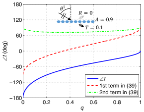
For the time being, let us assume that in (35). From (34), the transmission phase is expressed as
| (39) |
In (39), the quantity is positive and as , . Now, we inspect the numerators in the argument of the arctangent functions in (39). For the second arctangent, it is seen that remains positive in (i.e., its entire range) for all possible values of . The numerator in the first arctangent function has a range
| (40) |
From (37), we note that the lower limit in (40) is a negative quantity, while the upper limit is a positive one, for all possible . Hence, the first term in (39) changes from to as is increased from 0 to 1. The second term in (39) stays in the range between 0 and , but it reaches at , . Hence, we expect a range of for the transmission phase, in . For an example case of , Fig. 4 shows the transmission phase with respect to . It can be seen that there exists a unique value of for achieving a desired value of .
For synthesizing a transmission phase in , a meta-atom design strategy can be described as follows. For a given absorptance , the transmission magnitude is fixed at for a reflectionless response. The phase angle spans as a function of in . Equation (39) can be solved for the value of that achieves a desired transmission phase and the corresponding value of follows. The associated value of is obtained from (35). At the design frequency and the incidence angle , a meta-atom is designed by determining a combination of values for , , , and for giving the determined ratios and .
A transmission phase in the range can be designed using the negative branch for in (35). For , we note from (34) that
| (41) |
which is an opposite number for (39). Therefore, to design a value of in , meta-atom parameters can be first determined for achieving a phase of , following the approach described above for realizing a transmission phase in . Then, the sign of needs to be changed, which can be achieved by setting , i.e., by choosing the resonance frequency of the lossy meta-atom lower than the design frequency.
Combining the two separate cases of the desired transmission phase being in or , we conclude that a reflectionless metasurface can be designed using lossy meta-atoms following the Lorentz dispersion model to achieve a transmission phase in a full range at any level of absorption at any oblique angle of incidence.
V Numerical examples
In this section, we will present different alternatives for Huygens’ metasurfaces where the tangential and normal electric dipole moments are carefully engineered for satisfying the reflectionless condition while providing a complete transmission phase coverage. We will explore the possibilities for the design of metasurfaces at microwave and optical frequencies for lossless and lossy scenarios.
V.1 Reactively-loaded tilted thin conductor strip dipole array
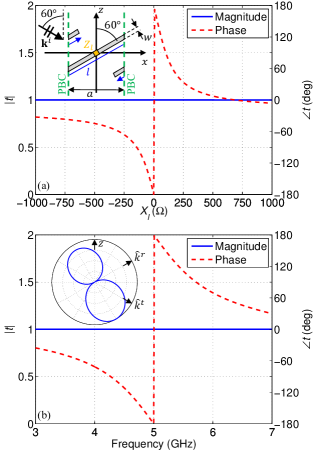
At microwave frequencies, the direction of induced electric dipole moments can be easily controlled using thin conductor wires and traces. For supporting both tangential and normal electric dipoles, a straight thin conductor dipole can be tilted to produce zero reflection. Here, it is noted that (24) is the zero reflection condition for point dipoles. For meta-atoms of practical dimensions, zero reflection corresponds to a scattering pattern null in the specular reflection direction. For a straight conductor dipole of any length, aligning the dipole axis in the specular reflection direction guarantees . The transmission characteristics of a tilted straight dipole array are analyzed in Fig. 5. For a TM-polarized plane-wave illumination at an incidence angle of 60°, a perfect electric conductor (PEC) strip dipole tilted at the same 60° angle in the opposite direction constitutes the meta-atom, as shown in the inset of Fig. 5(a). At the middle point of the dipole, a lumped load with an impedance is connected. While providing tunability for , such a load does not affect the reflectionless property. At a design frequency of 5 GHz, the unit-cell dimensions are chosen to be , so that there are no higher-order propagating Floquet modes. For an electrically thin width of , the length of the strip was adjusted to such that the transmission phase for the unloaded case () is equal to . The dipole meta-atom extends slightly into neighboring cells. Using a phase-shift periodic boundary condition (PBC) on the four vertical walls of the unit cell, the scattering characteristics of an infinitely large planar array were simulated using FEKO 2017 by Altair.
At the design frequency, the magnitude and phase of are plotted in Fig. 5(a) with respect to the reactance of the reactive load impedance . Since the meta-atom is lossless and the dipole does not reflect, the transmission magnitude is constant at unity. By loading the dipole with different reactance , the transmission phase can be adjusted to any value in the range . Not the entire phase range is visible in Fig. 5(a). Simulations with large loading reactances show that the transmission phase approaches a single value of from different directions as . Considering that the dipole meta-atom is not electrically short, large loading reactances will not make it effectively non-existent. Instead, the meta atom will appear as two narrowly separated collinear dipoles of a length each.
For an unloaded dipole , Fig. 5(b) plots the transmission coefficient with respect to frequency. A standard Lorentz-type resonant frequency response is observed for the phase. In the inset, the normalized unit-cell scattering pattern at 5 GHz in the -plane is shown as a polar plot. The length of the dipole meta-atom of nearly a half wavelength makes the pattern deviate noticeably from that of a point dipole shown in Fig. 3(b). Still, a scattering null is synthesized in the reflection direction due to the tilt. In this design, the bandwidth of full power transmission is in principle infinite. This is due to satisfaction of the no reflection condition of a geometrical origin. For a tilted straight dipole, the normal and tangential surface-averaged electric polarizations, , , have the exact same frequency dispersion. If zero reflection is achieved via a balance of electric and equivalent magnetic polarizations as is done in Huygens’ metasurfaces, the high-transmission frequency bandwidth is not expected to be wide.
V.2 Impedance-loaded tilted strip dipole array
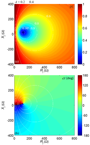
To the tilted conductor dipole array of Sec. V.1, loss can be introduced to make the metasurface absorptive. For this purpose, a resistive component can be incorporated into the load impedance in Fig. 5(a). At the same time, adjusting the reactance part is expected to give a capability to tune the transmission phase. To the tilted PEC strip dipole array considered in Sec. V.1, a complex load with an impedance is attached to the center point of the meta-atom. In the range , , the reflection and transmission coefficients were simulated using FEKO at 5 GHz. The simulated reflection coefficient is zero. The transmission coefficient is shown in Fig. 6. The magnitude plot in Fig. 6(a) demonstrates that the entire range of between zero and unity is available for synthesis. For visualization, a few contours for constant- (in terms of the absorptance ) values are also plotted. The same contours are reproduced in Fig. 6(b), where the transmission phase is plotted. It is clear that for any given value of , an arbitrary phase in a complete range can be achieved in principle by selecting an appropriate value for . In practice, extreme values of , required for some combinations of and may be difficult to realize and consequently limit the synthesis range.
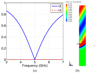
In Fig. 6(a), an extreme case of full absorption is observed with a selection of load impedance . If the received power is guided to a receiving circuitry rather than dissipated as heat, the design corresponds to a planar receiving array with a 100% receiving efficiency. The frequency responses of and are shown in Fig. 7(a). The metasurface does not transmit nor reflect at the design frequency of 5 GHz. The bandwidth is reflection zero is extremely wide. At 5 GHz, a snapshot at time of the -component of the total magnetic field in the -plane is plotted over the unit-cell dimension of in Fig. 7(b). Only the fields associated with the incident wave is visible above the metasurface and zero field penetrates behind the dipole array.
In this design, absorption occurs at the load connected to the otherwise lossless meta-atom. Instead, it is possible to design an absorber based on a distributed loss mechanism. One approach will be realizing the dipole meta-atom using lossy conductive material such as conductive ink films, modeled as a resistive impedance sheet Wang et al. (2017). Such a lossy strip array variant was designed for perfect absorption at 5 GHz and numerically analyzed. Its simulated scattering characteristics exhibit the same qualitative behavior presented in Fig. 7 (not shown).
V.3 Array of dielectric bars of rectangular cross section
Here we give an example of a high-transmission array offering full control of the transmission phase in the optical domain. In order to ensure small dissipation losses, we use an all-dielectric metasurface formed by an array of parallel bars made of a lossless high refractive index dielectric () with the axis of the bars oriented along the -direction. Due to the 2-D nature of the problem, the -periodicity is infinite so we ensure the absence of higher order modes propagating in this direction. In conventional realizations of high-transmission all-dielectric metasurfaces, the Huygens regime is realized by exciting both electric and magnetic moments at the operational frequency. Here, we illuminate the array by an obliquely propagating plane wave to ensure excitation of both tangential and normal electric polarizations and utilize the theory in this paper to realize a full transmission with a complete phase control. Following the previous example, we consider a TM-polarized incident plane wave [see Fig. 9(a)] and we define the incidence angle to be 45°.
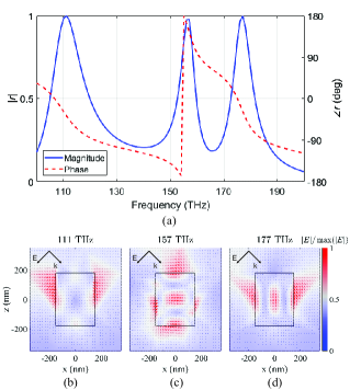
The reflection spectrum is presented in Fig. 8(a) when the periodicity is nm, the width is nm and the height is nm. It exhibits three reflection maxima which correspond to three dipole-mode resonances. The first reflection peak, at 111 THz, corresponds to a tangentially oriented magnetic dipole. Figure 8(b) shows the electric field vector in the -plane, where we can see that the electric field circulates inside the bars generating an out-of-plane magnetic dipole moment. At 157 THz, the reflection peak is caused by the resonance of a tangential electric dipole, as we can see in Fig. 8(c). The third resonance peak, at 177 THz, corresponds to the resonance of a normal electric dipole [see Fig. 8(d)]. Adjusting the shape parameters of the bars, the magnitude and phase of the induced dipoles can be tuned to fulfill the conditions in (24).
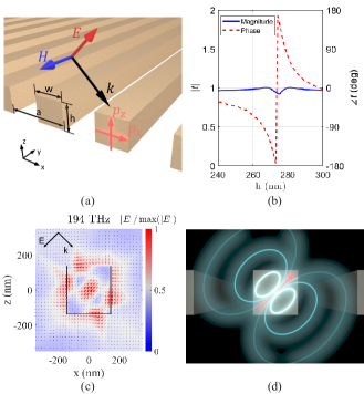
Finally, a combination of and can be tuned to transmit the incident light with required phase variations within the range. We consider a periodic array as shown in Fig. 9(a) with a period nm. The bars have a rectangular cross section with a height and a width nm. Figure 9(b) shows the transmission magnitude and phase for arrays of bars of different sizes, as a function of . We see that the transmission phase indeed varies within the full range while the transmission magnitude remains close to unity. Figures 9(c,d) show the calculated field distribution and a conceptual illustration of an excited tilted electric dipole moment for nm. The simulations were performed using ANSYS HFSS, setting PBCs on the vertical walls of the unit cell.
For absorptive applications, an array of dielectric bars made from a suitable lossy material is a straightforward extension of the high-transmission array in Fig. 9. An optical analogue of the array of tilted dipoles in Sec. V.2 is another possibility. Using the approach of lossy surface impedance realization in Monti et al. (2016) exploiting the surface dispersion of nanoparticles, it can be envisaged that metal nanoparticles are deposited on some dielectric support having periodic slanted walls. The tilt angle of the dielectric support can enforce (24). The surface resistance may be designed to achieve various levels of absorption, including complete absorption. This approach needs further investigation.
VI Conclusion
For polarization-preserving transmissive metasurface, it has been shown that the origin of a full transmission capability together with a complete phase coverage is synthesis of an asymmetric scattering pattern with respect to the metasurface plane. In Huygens’ meta atoms, a tangential magnetic dipole is responsible for creating anti-symmetric scattering. An alternative meta-atom arrangement is available for full transmission in oblique TM-polarization scattering, as a combination of tangential and normal electric dipoles. A particular realization is an array of tilted straight conductor dipole meta-atoms with the dipole axis aligned with the reflection direction. The geometrical nature of the synthesized scattering null allows an extremely wide bandwidth of zero reflection. In the presence of loss in constituent materials or intended power absorption, it has been analytically proven and demonstrated using a numerical example that a complete transmission phase coverage is possible for reflectionless metasurfaces. The operation principle and the new design strategy presented in this study will facilitate development of a new class of transmissive metasurfaces for wave manipulation with high power efficiencies.
Acknowledgment
This work was supported in part by the Academy of Finland (project 287894).
References
- Holloway et al. (2012) C. L. Holloway, E. F. Kuester, J. A. Gordon, J. O’Hara, J. Booth, and D. R. Smith, “An overview of the theory and applications of metasurfaces: the two-dimensional equivalents of metamaterials,” IEEE Antennas Propag. Mag. 54, 10 (2012).
- Kildishev et al. (2013) A. V. Kildishev, A. Boltasseva, and V. M. Shalaev, “Planar photonics with metasurfaces,” Science 339, 1232009 (2013).
- Yu and Capasso (2014) N. Yu and F. Capasso, “Flat optics with designer metasurfaces,” Nat. Mater. 13, 139 (2014).
- Meinzer et al. (2014) N. Meinzer, W. L. Barnes, and I. R. Hooper, “Plasmonic meta-atoms and metasurfaces,” Nat. Photon. 8, 889 (2014).
- Glybovski et al. (2016) S. B. Glybovski, S. A. Tretyakov, P. A. Belov, Y. S. Kivshar, and C. R. Simovski, “Metasurfaces: From microwaves to visible,” Phys. Rep. 634, 1 (2016).
- Chen et al. (2016) H.-T. Chen, A. J. Taylor, and N. Yu, “A review of metasurfaces: physics and applications,” Rep. Prog. Phys. 79, 076401 (2016).
- Hansen (2009) R. C. Hansen, Phased Array Antennas, 2nd ed. (Wiley, Hoboken, NJ, 2009).
- Yu et al. (2011) N. Yu, P. Genevet, M. A. Kats, F. Aieta, J.-P. Tetienne, F. Capasso, and Z. Gaburro, “Light propagation with phase discontinuities: generalized laws of reflection and refraction,” Science 334, 333 (2011).
- Pfeiffer and Grbic (2013a) C. Pfeiffer and A. Grbic, “Metamaterial Huygens’ surfaces: tailoring wave fronts with reflectionless sheets,” Phys. Rev. Lett. 110, 197401 (2013a).
- Aieta et al. (2012a) F. Aieta, P. Genevet, N. Yu, M. A. Kats, Z. Gaburro, and F. Capasso, “Out-of-plane reflection and refraction of light by anisotropic optical antenna metasurfaces with phase discontinuities,” Nano Lett. 12, 1702 (2012a).
- Pfeiffer et al. (2014) C. Pfeiffer, N. K. Emani, A. M. Shaltout, A. Boltasseva, V. M. Shalaev, and A. Grbic, “Efficient light bending with isotropic metamaterial Huygens’ surfaces,” Nano Lett. 14, 2491 (2014).
- Yu et al. (2015) Y. F. Yu, A. Y. Zhu, R. Paniagua-Domínguez, Y. H. Fu, B. Luk’yanchuk, and A. I. Kuznetsov, “High-transmission dielectric metasurface with phase control at visible wavelengths,” Laser Photon. Rev. 9, 412 (2015).
- Monticone et al. (2013) F. Monticone, N. Mohammadi Estakhri, and A. Alù, “Full control of nanoscale optical transmission with a composite metascreen,” Phys. Rev. Lett. 110, 203903 (2013).
- Lin et al. (2014) D. Lin, P. Fan, E. Hasman, and M. L. Brongersma, “Dielectric gradient metasurface optical elements,” Science 345, 298 (2014).
- Wang et al. (2015) Q. Wang, X. Zhang, Y. Xu, Z. Tian, J. Gu, W. Yue, S. Zhang, J. Han, and W. Zhang, “A broadband metasurface-based terahertz flat-lens array,” Adv. Opt. Mater. 3, 779 (2015).
- Khorasaninejad et al. (2016) M. Khorasaninejad, W. T. Chen, R. C. Devlin, J. Oh, A. Y. Zhu, and F. Capasso, “Metalenses at visible wavelengths: Diffraction-limited focusing and subwavelength resolution imaging,” Science 362, 1190 (2016).
- Ni et al. (2013) X. Ni, A. V. Kildishev, and V. M. Shalaev, “Metasurface holograms for visible light,” Nat. Commun. 4, 2087 (2013).
- Huang et al. (2013) L. Huang, X. Chen, H. Mühlenbernd, H. Zhang, S. Chen, B. Bai, Q. Tan, G. Jin, K.-W. Cheah, C.-W. Qiu, J. Li, T. Zentgraf, and S. Zhang, “Three-dimensional optical holography using a plasmonic metasurface,” Nat. Commun. 4, 2808 (2013).
- Arbabi et al. (2015) A. Arbabi, Y. Horie, M. Bagheri, and A. Faraon, “Dielectric metasurfaces for complete control of phase and polarization with subwavelength spatial resolution and high transmission,” Nat. Nanotechnol. 10, 937 (2015).
- Zhao et al. (2012) Y. Zhao, M. A. Belkin, and A. Alù, “Twisted optical metamaterials for planarized ultrathin broadband circular polarizers,” Nat. Commun. 3, 870 (2012).
- Pfeiffer and Grbic (2013b) C. Pfeiffer and A. Grbic, “Millimeter-wave transmitarrays for wavefront and polarization control,” IEEE Trans. Microw. Theory Techn. 61, 4407 (2013b).
- Grady et al. (2013) N. K. Grady, J. E. Heyes, D. R. Chowdhury, Y. Zheng, M. T. Reiten, A. K. Azad, A. J. Taylor, D. A. R. Dalvit, and H.-T. Chen, “Terahertz metamaterials for linear polarization conversion and anomalous refraction,” Science 340, 1304 (2013).
- Aieta et al. (2012b) F. Aieta, P. Genevet, M. A. Kats, N. Yu, R. Blanchard, Z. Gaburro, and F. Capasso, “Aberration-free ultrathin flat lenses and axicons at telecom wavelengths based on plasmonic metasurfaces,” Nano Lett. 12, 4932 (2012b).
- Zheng et al. (2015) G. Zheng, H. Mühlenbernd, M. Kenney, G. Li, T. Zentgraf, and S. Zhang, “Metasurface holograms reaching 80% efficiency,” Nat. Nanotech. 10, 308 (2015).
- Shalaev et al. (2015) M. I. Shalaev, J. Sun, A. Tsukernik, A. Pandey, K. Nikolskiy, and N. M. Litchinitser, “High-efficiency all-dielectric metasurfaces for ultracompact beam manipulation in transmission mode,” Nano Lett. 15, 6261 (2015).
- Decker et al. (2015) M. Decker, I. Staude, M. Falkner, J. Dominguez, D. N. Neshev, I. Brener, T. Pertsch, and Y. S. Kivshar, “High-efficiency dielectric Huygens’ surfaces,” Adv. Optical Mater. 3, 813 (2015).
- Chong et al. (2016) K. E. Chong, L. Wang, I. Staude, A. R. James, J. Dominguez, S. Liu, G. S. Subramania, M. Decker, D. N. Neshev, I. Brener, and Y. S. Kivshar, “Efficient polarization-insensitive complex wavefront control using Huygens’ metasurfaces based on dielectric resonant meta-atoms,” ACS Photon. 3, 514 (2016).
- Wong et al. (2015) J. P. S. Wong, M. Selvanayagam, and G. V. Eleftheriades, “Polarization considerations for scalar Huygens metasurfaces and characterization for 2-D refraction,” IEEE Trans. Microw. Theory Techn. 63, 913 (2015).
- Epstein and Eleftheriades (2016) A. Epstein and G. V. Eleftheriades, “Huygens’ metasurfaces via the equivalence principle: design and applications,” J. Opt. Soc. Am. B 33, A31 (2016).
- Cai et al. (2017a) T. Cai, S. Tang, G. Wang, H. Xu, S. Sun, Q. He, and L. Zhou, “High-performance bifunctional metasurfaces in transmission and reflection geometries,” Adv. Opt. Mater. 5, 1600506 (2017a).
- Luo et al. (2017) W. Luo, S. Sun, H.-X. Xu, Q. He, and L. Zhou, “Transmissive ultrathin Pancharatnam-Berry metasurfaces with nearly 100% efficiency,” Phys. Rev. Appl. 7, 044033 (2017).
- Cai et al. (2017b) T. Cai, G. Wang, S. Tang, H. Xu, J. Duan, H. Guo, F. Guan, S. S. Q. He, and L. Zhou, “High-efficiency and full-space manipulation of electromagnetic wave fronts with metasurfaces,” Phys. Rev. Appl. 8, 034033 (2017b).
- Niemi et al. (2013) T. Niemi, A. O. Karilainen, and S. A. Tretyakov, “Synthesis of polarization transformers,” IEEE Trans. Antennas Propag. 61, 3102 (2013).
- Albooyeh et al. (2017) M. Albooyeh, D.-H. Kwon, F. Capolino, and S. A. Tretyakov, “Equivalent realizations of reciprocal metasurfaces: role of tangential and normal polarization,” Phys. Rev. B 95, 115435 (2017).
- Huang et al. (2010) X.-R. Huang, R.-W. Peng, and R.-H. Fan, “Making metals transparent for white light by spoof surface plasmons,” Phys. Rev. Lett. 105, 243901 (2010).
- Alù et al. (2011) A. Alù, G. D’Aguanno, N. Mattiucci, and M. J. Bloemer, “Plasmonic Brewster angle: broadband extraordinary transmission through optical gratings,” Phys. Rev. Lett. 106, 123902 (2011).
- Fan et al. (2012) R.-H. Fan, R.-W. Peng, X.-R. Huang, J. Li, Y. Liu, Q. Hu, M. Wang, and X. Zhang, “Transparent metals for ultrabroadband electromagnetic waves,” Adv. Mater. 24, 1980 (2012).
- Bohren and Huffman (2004) C. F. Bohren and D. R. Huffman, Absorption and Scattering of Light by Small Particles (Wiley-VCH, Weinheim, Germany, 2004).
- Asadchy et al. (2015) V. S. Asadchy, I. A. Faniayeu, Y. Ra’di, S. A. Khakhomov, I. V. Semchenko, and S. A. Tretyakov, “Broadband reflectionless metasheets: frequency-selective transmission and perfect absorption,” Phys. Rev. X 5, 031005 (2015).
- Paniagua-Domínguez et al. (2016) R. Paniagua-Domínguez, Y. F. Yu, A. E. Miroshnichenko, L. A. Krivitsky, Y. H. Fu, V. Valuckas, L. Gonzaga, Y. T. Toh, A. Y. S. Kay, B. Luk’yanchuk, and A. I. Kuznetsov, “Generalized Brewster effect in dielectric metasurfaces,” Nat. Commun. 7, 10362 (2016).
- Green (1966) R. B. Green, “Scattering from conjugate-matched antennas,” IEEE Trans. Antennas Propag. AP-14, 17 (1966).
- Jin and Ziolkowski (2010) P. Jin and R. W. Ziolkowski, “Metamaterial-inspired, electrically small Huygens sources,” IEEE Antennas Wireless Propag. Lett. 9, 501 (2010).
- Ra’di et al. (2015) Y. Ra’di, C. R. Simovski, and S. A. Tretyakov, “Thin perfect absorbers for electromagnetic waves: theory, design, and realizations,” Phys. Rev. Appl. 3, 037001 (2015).
- Wang et al. (2017) X.-C. Wang, A. Díaz-Rubio, and S. A. Tretyakov, “An accurate method for measuring the sheet impedance of thin conductive films at microwave and millimeter-wave frequencies,” IEEE Trans. Microw. Theory Techn. 65, 5009 (2017).
- Monti et al. (2016) A. Monti, A. Toscano, and F. Bilotti, “Exploiting the surface dispersion of nanoparticles to design optical-resistive sheets and Salisbury absorbers,” Opt. Lett. 41, 3383 (2016).