The Construction and Commissioning of the Belle II iTOP Counter
Boqun Wang, on behalf of the Belle II iTOP
group
Department of Physics
University of Cincinnati
Cincinnati,
Ohio 45221, USA
Talk presented at the APS Division of Particles and Fields Meeting (DPF 2017), July 31-August 4, 2017, Fermilab. C170731
Abstract
The barrel-region particle identification detector is crucial for extending the physics reach of the Belle II experiment operating at the SuperKEKB accelerator. For this purpose, an imaging-Time-of- Propagation (iTOP) counter was developed, which is a new type of ring- imaging Cherenkov detector. The iTOP consists of 16 separate modules arranged azimuthally around the beam line. Each module consists of optical components fabricated from quartz (one mirror, one prism, and two bars), an array of micro-channel-plate photo-multiplier tubes (MCP-PMTs), and front-end electronics. The waveforms read out are processed by firmware, and the resulting pulse-heights and hit times are sent to the Belle II data acquisition system. The detector construction was completed and the detector installed by the summer of 2016, and since then the detector has undergone commissioning. This talk describes the construction and commissioning of the Belle II iTOP counter.
1 Introduction
The B factory is an collider running at the resonance energy to produce B meson pairs. The major B factories are Belle running at KEKB in Japan and BaBar running at PEP-II in US. These two facilities have collected in total of collision data. With this data set, they’ve reached physics achievements in areas like the CKM angle measurement, and measurement, semileptonic and leptonic B decays, rare B decays, physics, mixing and CP violation, physics at the , two-photon physics and new resonances.
The Belle II [1] detector at the SuperKEKB [2] accelerator is an upgrade of the Belle detector at the KEKB accelerator for searching for New Physics (NP), which is physics beyond the Standard Model (SM). The design luminosity of the upgraded accelerator is , which is 40 times larger than that of the KEKB collider. The nano-beam technology [3] is utilized to significantly squeeze the sizes of the beam bunches to achieve such high luminosity. The planned integrated luminosity taken by the Belle II detector is , which is around 50 times larger than that of Belle.
The iTOP (imaging-Time-Of-Propagation) counter [4, 5, 6, 7], which is the particle identification detector in the barrel region, is a newly designed sub-detector for the Belle II detector. It consists of a 2.7 m long quartz optics for the radiation and propagation of the Cherenkov light, an array of micro-channel- plate photo-multiplier tubes (MCP-PMT) [8] for photon detection, and wave-sampling front-end readout electronics [9, 10]. This article describes the construction and commissioning of the iTOP counter.
2 Detector Design
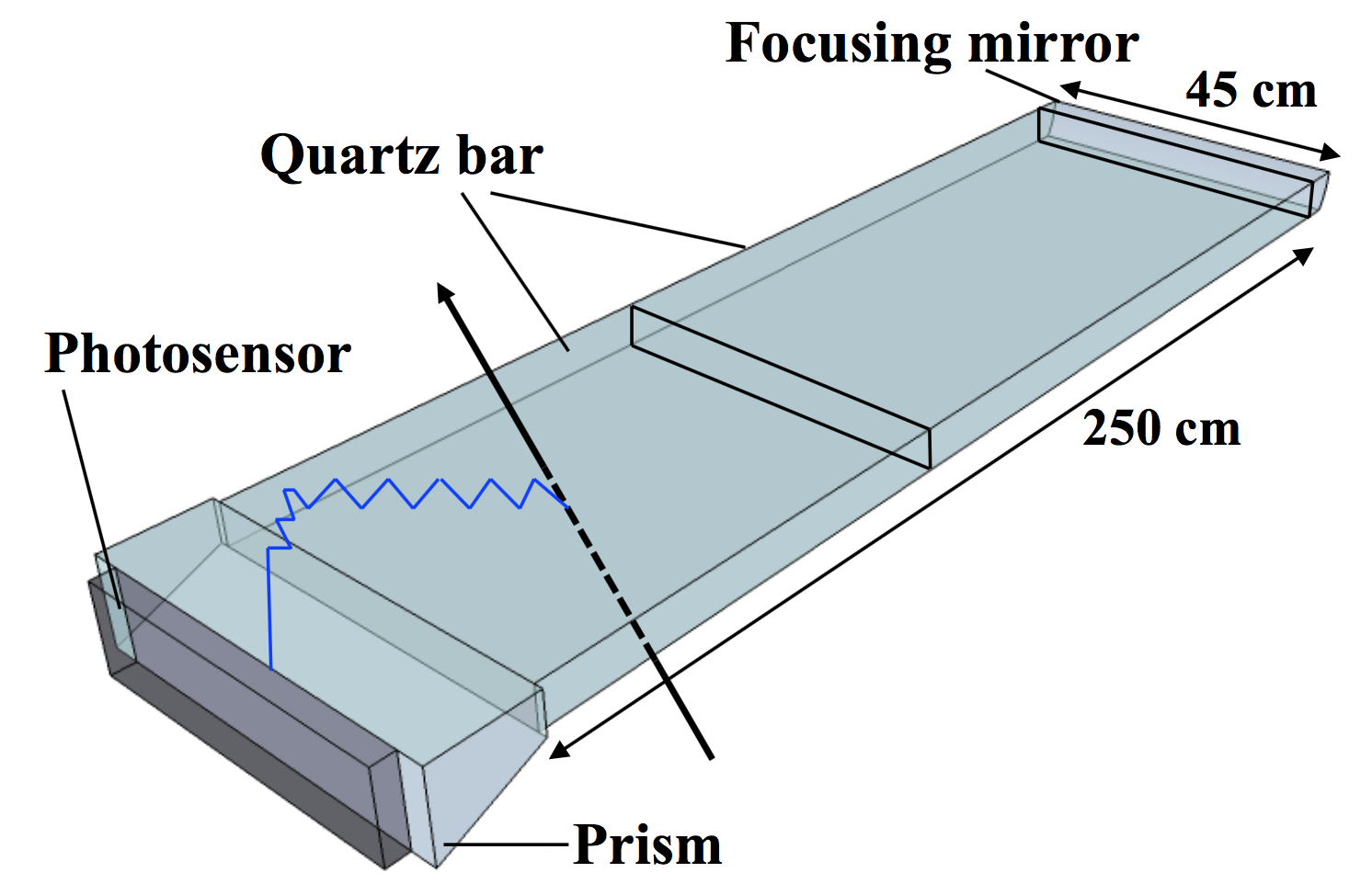
As shown in Figure 1, one iTOP module consists of two 1250 mm long, 450 mm wide and 20 mm thick bars. A reflective mirror with spherical surface is mounted at one end of the bars, and an expansion block called prism is mounted at the other end. All optics components are made of Corning 7980 synthetic fused silica, which has a high purity and no striae inside. There are 16 modules in total for the Belle II detector.
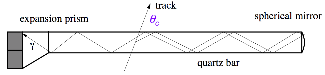
The diagram of the working principle of the iTOP counter is shown in Figure 2. The Cherenkov photons are emitted when a charged track goes through the quartz radiator, and the Cherenkov angle depends on the velocity of the charged track. With the momentum of the charged track given by the central drift chamber (CDC), the angle depends on the mass of the charged particle. The photons are collected by the MCP-PMTs after being reflected by the bar surfaces and the mirror. The resolution of the photon sensors and the front end electronics are required to be better than 50 ps, which is required to distinguish the time of propagation difference between Cherenkov photons from and tracks.
3 Module Construction
The construction process of the iTOP modules was started at the end of 2014 and all 17 modules, including one spare, were finished by April 2016. After testing with laser and cosmic rays, these modules were installed in the Belle II detector by May 2016.
3.1 QA of Quartz Optics
The optics of the iTOP counter needs to have very high optical quality to achieve the high K/ separation capability. The Cherenkov photons will be reflect 50 – 100 times inside the quartz radiator, so the surfaces of the quartz bars need to be highly polished. The requirement for surface roughness is 5 Å r.m.s., and for flatness the requirement is 6.3 . For all 34 bars needed, 30 were produced by Zygo Corporation (USA) and 4 were produced by Okamoto Optics Works (Japan).
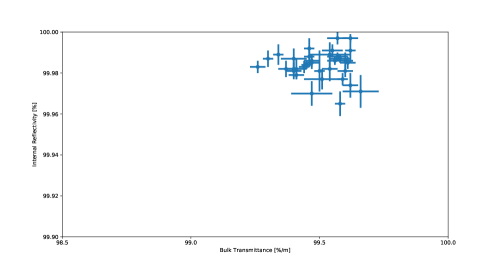
The quartz bars were procured by the vendors and delivered directly to KEK. After receiving these bars, they were mounted on the measurement stage for the QA (Quality Assurance) tests. Laser beam was injected to one surface of the bar and went out from the other surface. By measuring the beam intensity before and after it went through the quartz bar, the bulk transmission can be measured. For the internal reflectivity measurement, the methods were similar except the laser beam was injected with a certain angle. The requirements for bulk transmittance and internal reflectivity were 98.5 %/m and 99.9 % per reflection, respectively. As shown in Figure 3, all received quartz bars fulfilled the requirements.
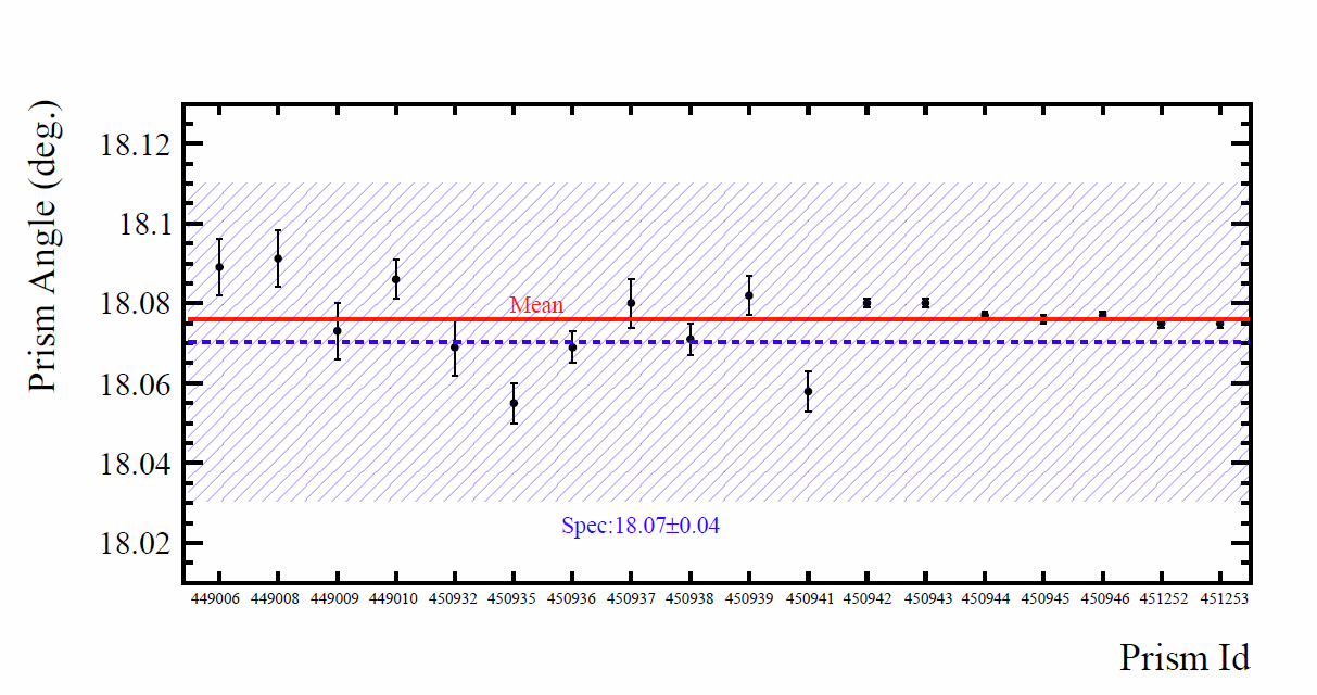
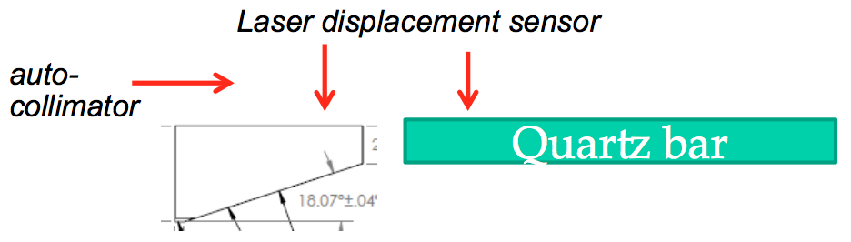
The mirrors and prisms were delivered to University of Cincinnati in US after procurement. After the QA testing, they were delivered to KEK for module assembly. The angle of the tilted surface of the prism and the radius and reflectivity of the mirror’s spherical surface were the most important for the QA testing. They were measured by injecting laser beam to the optics and measure the laser direction after it went through or reflected by the optics. The results are summarized in Figure 4. All optics fulfilled the requirements.


3.2 Alignment and Gluing
After the QA process was finished and all the quartz optics passed the requirements, two quartz bars, one prism and one mirror were mounted on a gluing stage for precision alignment and gluing.
Two laser displacement sensors and an autocollimator were used for the alignment as shown in Figure 5. Laser displacement sensor was used to align the horizontal and vertical positions of two optics’ surfaces. Autocollimator accompanied with a mirror mounted on the optics was used to align the relative angle, both horizontal and vertical between two optics’ surfaces.
After the alignment, the optics were moved closer with a 50 100 gap. The joints between two optics were taped on 3 of 4 sides by using Teflon tape to make a “dam” to prevent the epoxy from flowing outside. After the mixture and centrifuge of the two parts of the epoxy, EPOTEK 301-2, the adhesive was applied from a syringe to the glue joint by using high pressure dry air. After applying, it took 3 4 days to be fully cured.
After curing, the excessive glue was removed by using Acetone. The alignment may have changed during the curing process, so it needed to be measured again. The achieved horizontal and vertical angle between the two optics near the glue joint was within 40 arcsec and 20 arcsec, respectively.
3.3 Module Assembly
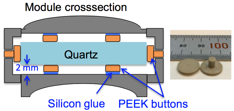
The completed iTOP optics was moved into a Quartz Bar Box (QBB). The QBB consisted of honeycomb panels held together with thin aluminum side-rails. On the inner surfaces were attached PEEK buttons, which supported the quartz optics (see Figure 6). The height of the PEEK buttons were tuned precisely according to the alignment of the optics. The QBB was attached to a support structure called a ”strong back”, with which the module sag can be kept below 0.5 mm.
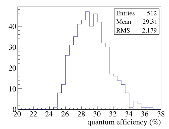
The micro-channel-plate photo-multiplier tubes (MCP-PMT) Hamamatsu SL10 is the photon sensor for the detection of the Cherenkov photons. It has enough gain to detect single photons in 1.5T of the Belle II magnet field. The quantum efficiencies of all MCP-PMTs installed to iTOP modules are shown in Figure 7. The average quantum efficiency is 29.3%, which is much better than the requirement of 24%.
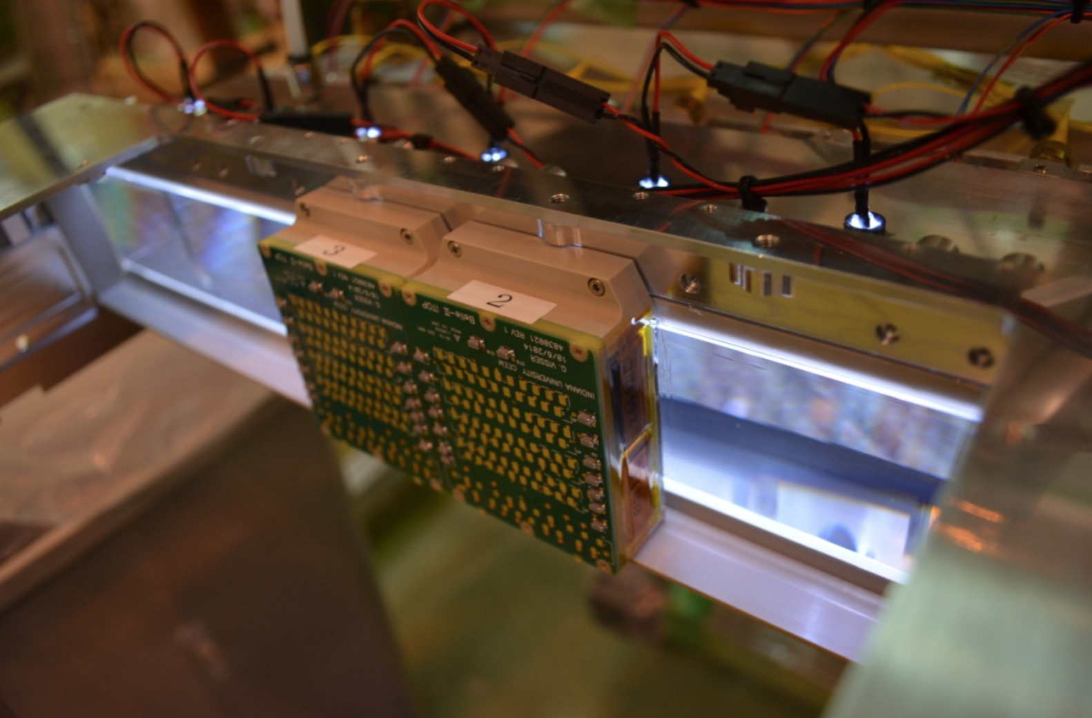
After the completion of the QBB assembly, the PMT modules, which consist of four MCP-PMTs for each, were installed on the prism surface of the module, as shown in Figure 7.
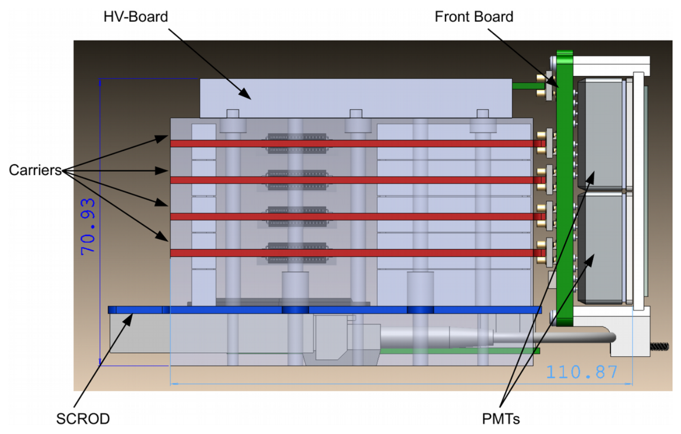
The front-end read-out electronics consists of eight-channel, multi- giga sample per second, transient waveform sampler ASICs and the FPGAs that control the ASICs and process the data. Together with the HV boards, they constitute the board-stacks that were installed in the module as shown in Figure 8.
3.4 Installation
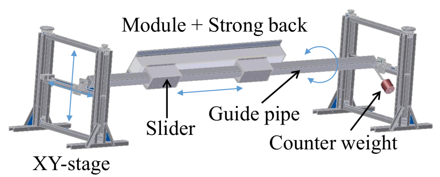
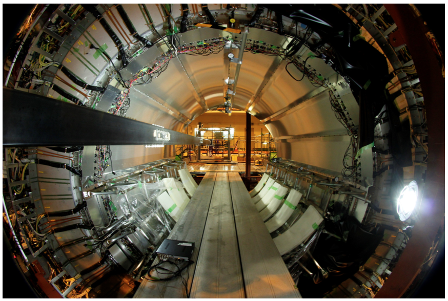
After the construction and testing with cosmic ray and laser, the iTOP modules were transferred by truck to the experimental hall for installation. A specially designed movable stage was used for the installation, as shown in Figure 9. The module to be installed was mounted on a guide pipe, which was supported by the x-y stages on the two ends. The module was able to move and rotate along the guide pipe. The module deflection during the installation process was monitored by deflection sensors, and it was required to be less than 0.5 mm. The installation of all the modules was completed in May, 2016. The 16 installed modules are shown in Figure 9. More details can be found in Ref. [11].
4 Commissioning with Cosmic Ray
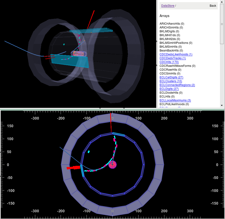
After the installation of the iTOP modules, laser data and cosmic ray data have been taken in order to debug the firmware and the local iTOP DAQ (data acquisition) system. When other detectors such as CDC (Central Drift Chamber) has been installed, a joint cosmic ray data taking with all installed sub-detectors, including CDC, TOP, ECL (electromagnetic calorimeter) and KLM ( and muon detector), started from the beginning of July, 2017 and lasted for around 2 months. During this period, various components of the global DAQ system has been tested and confirmed working. An event display of one cosmic ray track is shown in Figure 10. From this figure a cosmic ray track clearly went across two iTOP modules, while it was bending inside the magnetic field and leaving hits in the CDC and ECL.
5 Summary
The iTOP counter is an important particle identification device for the Belle II detector. Here we described the design, construction and commissioning of the iTOP counter. The last iTOP module was completed and installed in May 2016, and the Belle II detector was moved into the beam line in April 2017. The global cosmic ray data taking started in the beginning of July and lasted for around two months. Now other sub-detectors, such as ARICH (Aerogel Ring-Imaging Cherenkov detector) and vertex detectors, will be installed soon and the physics data taking will be started around late 2018.
References
- [1] T. Abe, et al., KEK-REPORT-2010-1, 2010.
- [2] Y. Ohnishi, et al., Prog. Theor. Exp. Phys. (2013) 2013 (3): 03A011.
- [3] P. Raimondi, talk given at the 2nd SuperB workshop, Frascati, http://www.lnf.infn.it/conference/superb06/talks/raimondi1.ppt, 2006.
- [4] K. Inami, Nucl. Instr. and Meth. A 595 (2008) 96.
- [5] K. Matsuoka, Nucl. Instr. and Meth. A 732 (2013) 357.
- [6] K. Inami, Nucl. Instr. and Meth. A 766 (2014) 5.
- [7] B. Wang, Nucl. Instr. and Meth. A 766 (2014) 204.
- [8] K. Matsuoka, For the Belle II PID group, PoS(TIPP2014)093.
- [9] Andrew M 2012 IEEE Realtime Conf. Rec. 1–5.
- [10] Andrew M 2014 PoS (TIPP2014) 171.
- [11] K. Suzuki et. al., Nucl. Instrum. Methods A in press, DOI: 10.1016/j.nima.2017.03.052.