Current Address: ]Institute of Theoretical Physics and Astrophysics, University of Kiel, Leibnizstrasse 15, 24098 Kiel, Germany
Current Address: ]King Abdullah university of science and technology ( KAUST), Physical Science and Engineering Division ( PSE), Thuwal 23955-6900, Saudi Arabia
Comparative study of electronic and magnetic properties of MPc (M = Fe, Co) molecules physisorbed on 2D \ceMoS2 and graphene
Abstract
In this paper, we have done a comparative study of electronic and magnetic properties of iron phthalocyanine (FePc) and cobalt phthalocyanine (CoPc) molecules physisorbed on monolayer of \ceMoS2 and graphene by using density functional theory. Various different types of physisorption sites have been considered for both surfaces. Our calculations reveal that the MPc molecules prefer the S-top position on \ceMoS2. However, on graphene, FePc molecule prefers the bridge position while CoPc molecule prefers the top position. The MPc molecules are physisorbed strongly on the \ceMoS2 surface than the graphene ( 2.5 eV higher physisorption energy). Analysis of magnetic properties indicates the presence of strong spin dipole moment opposite to the spin moment and hence a huge reduction of effective spin moment can be observed. Our calculations of magnetic anisotropy energies using both variational approach and order perturbation approach indicate no significant changes after physisorption. In case of FePc, an out-of-plane easy axis and in case of CoPc, an in-plane easy axis can be seen. Calculations of work function indicate a reduction of \ceMoS2 work function 1 eV due to physisorption of MPc molecules while it does not change significantly in case of graphene.
I Introduction
The feasibility of spin and charge degrees of freedom manipulation has made molecular electronics and spintronics an interesting field of research. Metal-organic molecules with a metal atom center is a key prospect in this field. The efficient spin manipulation has made these molecules an attractive choice for various kind of spin dependent electronics applications. Leoni et al. (2011); Wende et al. (2007); Dediu et al. (2009); Bhandary et al. (2013a) Metal phthalocyanines (MPc) are porphyrinoid macrocyclic complexes and symmetric organic molecules with a metal atom (M) at the center surrounded by four bonded N atom and four non bonded N atom. The phthalocyanine molecules do not have any out-of-plane ligands. Hence, they can remain planar on a surface and enhance the surface-molecular interactions. These molecules, especially transition metal phthalocyanines have application prospects in various scientific fields e. g., photovoltaics, organic solar cells, molecular electronics and spintronics etc. Martinez-Diaz et al. (2010); Ishikawa (2010); Bogani and Wernsdorfer (2008); Liu et al. (2013); Stróżecka et al. (2012); Fu et al. (2007); Ragoussi et al. (2012); Antonietta Loi et al. (2003) Long range structural ordering on metallic surface and influence of surface on the electronic properties has also been experimentally realized. Betti et al. (2010)
However, for many of these applications, the Pc molecules need to be absorbed or hosted on some kind of molecule surfaces. In this context, the use of stable ultra thin atomic materials are an automatic choice for future devices. Two dimensional materials like graphene are one of the automatic choices in this regard where it is already being used quite significantly. Neto et al. (2009); Geim and Novoselov (2007); Geim (2009) Apart from graphene, \ceMoS2 is also another choice of materials due to its interesting properties. Two dimensional (2D) \ceMoS2 being an ultra-thin semiconductor with unique electronic and optical characteristics, has potential application in optoelectronics, in fluorescence imaging, in photo catalysis, in solar cells, in valley electronics, as photodynamic, photothermal materials and even in biomedicine as antibacterial agents. Xie (2016); Kudo and Miseki (2009); Li et al. (2013); Wang et al. (2012); Chou et al. (2013); Liu et al. (2014a); Yang et al. (2014) Monolayer \ceMoS2 has a direct band gap of 1.9 eV, which is suitable to absorb visible light. Haldar et al. (2015); Liu et al. (2014b) Tuning of electronic and optical properties of \ceMoS2 by means of molecular charge transfer using organic molecules adsorption have also been reported in recent theoretical studies. Jing et al. (2014) Effect of \ceCuPc and \ceTiOPc physisorption in optical properties on 2D \ceMoS2 have also been investigated recently. Choudhury et al. (2017)
Magnetic anisotropy energies are also quite important factor related to spintronics applications. For example, to increase storage density one needs to have an out-of-plane magnetization and magnetic molecules can play an important role into it. Strong magnetic anisotropy for metallic atoms in presence of graphene have been reported in recent studies. Kandpal et al. (2012); Porter and Stroud (2012) Graphene induced magnetic anisotropy in two dimensional phthalocyanine network also has been reported recently. Lisi et al. (2015) Motivated by these studies, we have also investigated magnetic anisotropy energies of FePc and CoPc magnetic molecules physisorbed on \ceMoS2 and graphene.
In low dimensional system such as clusters, organometallic molecules with metal center, spin-dipole interaction () can become very important. Šipr et al. (2009); Bhandary et al. (2011); Stepanow et al. (2010). These spin-dipole contributions, originating from non isotropic spin densities, may have opposite sign from the spin moment and hence reducing the effective moment ( = +7). This effective moment can be measured in X-ray magnetic circular dichroism (XMCD) experiments. Herper et al. (2013)
In this paper, we have done a comparative study of electronic and magnetic properties of metal phthalocyanine molecules physisorbed on monolayer of graphene and 2D \ceMoS2 sheet by using density functional theory. Iron phthalocyanine (FePc) and cobalt phthalocyanine (CoPc) molecules were chosen as the representatives of metal phthalocyanine molecules. Our calculations reveal that the MPc molecules physisorbed strongly on the \ceMoS2 surface than the graphene. The stable physisorption sites are different for \ceMoS2 and graphene. We have compared the density of states with the free molecular states. Changes in work function, magnetic anisotropies and spin dipolar contribution due to the physisorption are also discussed in details. The plan of the paper is as follows. In the next section we will present the computational details followed by results and discussion in section III. In result and discussion section, we will first discuss about the structural properties [III.1] and then it will be followed by discussion of electronic structure [III.2], work function [III.2.3], spin dipole contributions [III.2.1] and magnetic anisotropy [III.2.2]. The conclusions are discussed in section IV
II Computational Details
All the calculations have been performed in a monolayer supercell of \ceMoS2 and graphene. The supercells of \ceMoS2 and graphene are generated by repeating the primitive cells respectively by 9 and 12 times in both and directions. The MPc (=Fe, Co) molecules was placed on top of these supercells. It is extremely important to reduce the interaction between periodic images of the physisorbed molecules and hence such a large size of supercell is essential. A vacuum of 20 Å is included to avoid the effect of vertical interaction. All the calculations have been performed using plane-wave based density functional code vasp. Kresse and Furthmüller (1996) The generalized gradient approximation of Perdew, Burke and Ernzerhof Perdew et al. (1996, 1997) has been used for the exchange-correlation potential. All the structures have been fully relaxed using the conjugate gradient method with the forces calculated using the Hellman-Feynman theorem. We have used the energy and the Hellman-Feynman force thresholds at 10-4 eV and 10-2 eV/Å respectively. We have used 500 eV cutoff energy to truncate the plane waves. A 3 3 1 Monkhorst-Pack -grid was used for all our calculations. To address the problem of electron correlation effect in the narrow states of metal atoms (Fe, Co), we have used a GGA+U approach following the formalism proposed by Dudarev et al. Dudarev et al. (1998) A Coulomb interaction term is added in according to the mean field Hubbard U formalism. Dudarev et al. (1998); Solovyev et al. (1994); Anisimov et al. (1997) The value of the exchange parameter, J, was chosen to be 1.0 eV. The value of Coulomb parameter, U, was chosen to be 4.0 eV and 6.0 eV, respectively, for FePc and CoPc. Wehling et al. (2011); Eelbo et al. (2013) These values were chosen as they correctly reproduce the electronic structure and magnetic properties of FePc and CoPc in gas phase.
The van der Waals interactions between the MPc molecules and the \ceMoS2 or graphene layer originate due to the fluctuating charge distribution and hence cannot be described by PBE functionals alone. Hence for all the calculations, we have included the van der Waals effect by adding a correction to the conventional Kohn-Sham DFT energy through pair wise force fields following the method of Tkatchenko-Scheffler. Tkatchenko and Scheffler (2009)
The physisorption energy for metal phthalocyanine molecule physisorbed on \ceMoS2 or graphene is defined as follows,
| (1) |
where,
-
i
is the total energy of either \ceMoS2 or graphene supercell
-
ii
is the total energy of the MPc molecules in the gas phase
-
iii
is the total energy of MPc physisorbed on \ceMoS2 or graphene supercell system.
III Results and discussions
III.1 Structural properties
We will begin our discussion of results from the analysis of structural properties and the energetics of the systems studied. We will first discuss the results of MPc physisorption on \ceMoS2 followed by the results of physisorption on graphene.
| FePc@ | Ea | Dh | |
|---|---|---|---|
| \ceMoS2 | (eV) | (total) | (Å) |
| S-Top | 6.21 | 2.0 | 3.18 |
| Bridge | 6.06 | 2.0 | 3.42 |
| Hex | 6.03 | 2.0 | 3.37 |
| Mo-Top | 5.98 | 2.0 | 3.39 |
| CoPc@ | Ea | Dh | |
|---|---|---|---|
| \ceMoS2 | (eV) | (total) | (Å) |
| S-Top | 6.18 | 1.0 | 3.21 |
| Bridge | 6.05 | 1.0 | 3.42 |
| Hex | 6.01 | 1.0 | 3.38 |
| Mo-Top | 5.96 | 1.0 | 3.40 |
To find out the most energetically favorable physisorbed position, we have considered different possible positions of the MPc molecules. These different positions of the molecule can be distinguished by the position of metal atom center with respect to the underlying surface layer of \ceMoS2 or graphene. For \ceMoS2, there are four possible positions, which are i) S-Top – when the metal atom center is at the top of S atom, ii) Mo-Top – when the metal atom center is at the top of Mo atom iii) Bridge – when the metal atom center is at the bridge position of two top layer S atom of \ceMoS2 and iv) Hex – when the metal atom center is at the hexagonal position formed by \ceMoS2. In the case of graphene, three positions are possible. Following the above terminology, these positions are i) C-Top, ii) Bridge and iii) Hex. In our calculations, MPc molecules are placed on the surfaces with a particular position and we have not considered any rotation of the molecules in the plane.
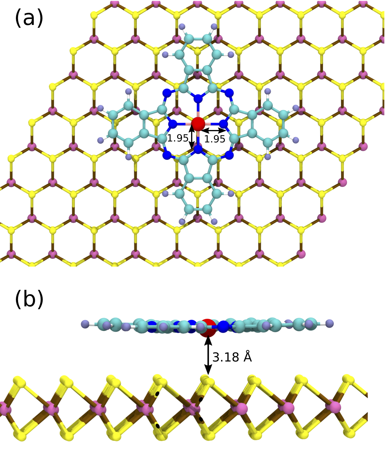
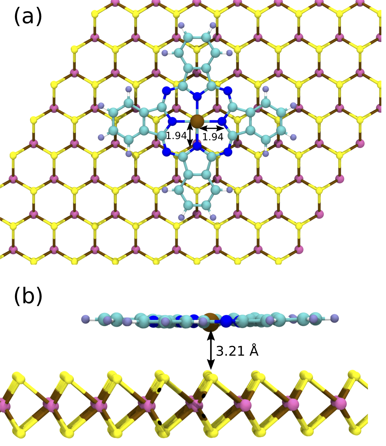
In table 1, we have shown the physisorption energies (), total magnetic moment () and vertical distance between the metal center and the \ceMos2 layer for all of the four FePc and CoPc physisorbed structures described before. From the analysis of physisorption energy (see table. 1), it is clear that for both FePc and CoPc, the energetically most stable structure is when the metal center of the MPc molecules reside exactly at the top of the S atom. Fig. 1 and Fig. 2 show the close up of schematic figure of energetically most stable structures of FePc and CoPc physisorption on \ceMoS2 respectively. For both cases, all four metal atoms to nitrogen distance remain identical – 1.95 Å for FePc and 1.94 Å for CoPc maintaining a symmetry. However, the vertical height from the \ceMoS2 layer are different for the two system. The vertical distance between FePc and CoPc molecule with \ceMoS2 layer is 3.18 Å and 3.21 Å respectively.
We have also calculated the Pc physisorption on graphene to compare the same with the Pc physisorption on \ceMoS2. To find out the most energetically favorable physisorption sites, we have optimized three different structures of Pc physisorbed on graphene. As stated previously, these positions are different according to the position of the metal atoms of the Pc relative to the C atom from the graphene layer.
| FePc@ | Ea | Dh | |
|---|---|---|---|
| \ceGr | (eV) | (total) | (Å) |
| Top | 3.38 | 2.0 | 3.37 |
| Bridge | 3.40 | 2.0 | 3.34 |
| Hex | 3.36 | 2.0 | 3.43 |
| CoPc@ | Ea | Dh | |
|---|---|---|---|
| \ceGr | (eV) | (total) | (Å) |
| Top | 3.39 | 1.0 | 3.39 |
| Bridge | 3.38 | 1.0 | 3.34 |
| Hex | 3.35 | 1.0 | 3.43 |
The calculated physisorption energy (), total magnetic moment () and vertical distance between the metal center and graphene layer (Dh) are tabulated in Table 2. The analysis of physisorption energies shows that for graphene, the most favorable site for FePc molecule physisorption is when the Fe metal center resides at the bridge position (figure not shown). This is quite different from the physisorption of iron porphyrin (FeP) molecule on graphene, where the energetically favorable physisorption position is on the top of C atom. Bhandary et al. (2013b) However, for CoPc molecule the most stable physisorption site on graphene is the top site, where the metal atom is on top of the carbon atom. A comparison of results listed in table 1 and table 2 show an interesting contrast between the two cases of MPc molecules physisorption on \ceMoS2 and graphene. It can be clearly observed that the physisorption energies of MPc physisorption are quite high on \ceMoS2 as compare to graphene. The high values of physisorption energy in \ceMoS2 are due to stronger hybridization of M- states with the S- orbitals of \ceMoS2. On graphene, the hybridization is relatively weak and hence the physisorption energies are much lower. The different strengths of hybridization are also reflected on the vertical distances of MPc molecules from the \ceMoS2 and graphene surface. For energetically most favorable physisorption position, the vertical distance between molecule metal center and graphene is 0.20 Å higher as compared to the vertical distance between molecule metal center and \ceMoS2.
It is also interesting to note that the physisorption energy differences between different position of MPc molecules on graphene are quite small ( 0.02 eV). However, on \ceMoS2 the physisorption energy differences between the most stable physisorption site and next probable site are substantially higher as compared to graphene ( 0.14 eV). The reason of this behavior lies in the fact that graphene is planar where as \ceMoS2 has S and Mo atoms in different layers.
Our analysis of the structural properties and energetics suggests that MPc molecules will be quite mobile on graphene surface, but they will be strongly physisorbed on \ceMoS2 surface. Thus, it will be possible to use 2D surface of \ceMoS2 to isolate single MPc molecules.
III.2 Electronic structure
In this subsection, we will discuss the electronic properties of the MPc molecules physisorbed on \ceMoS2 and graphene. We have used total density of states, site and projected densities of states for our analysis.
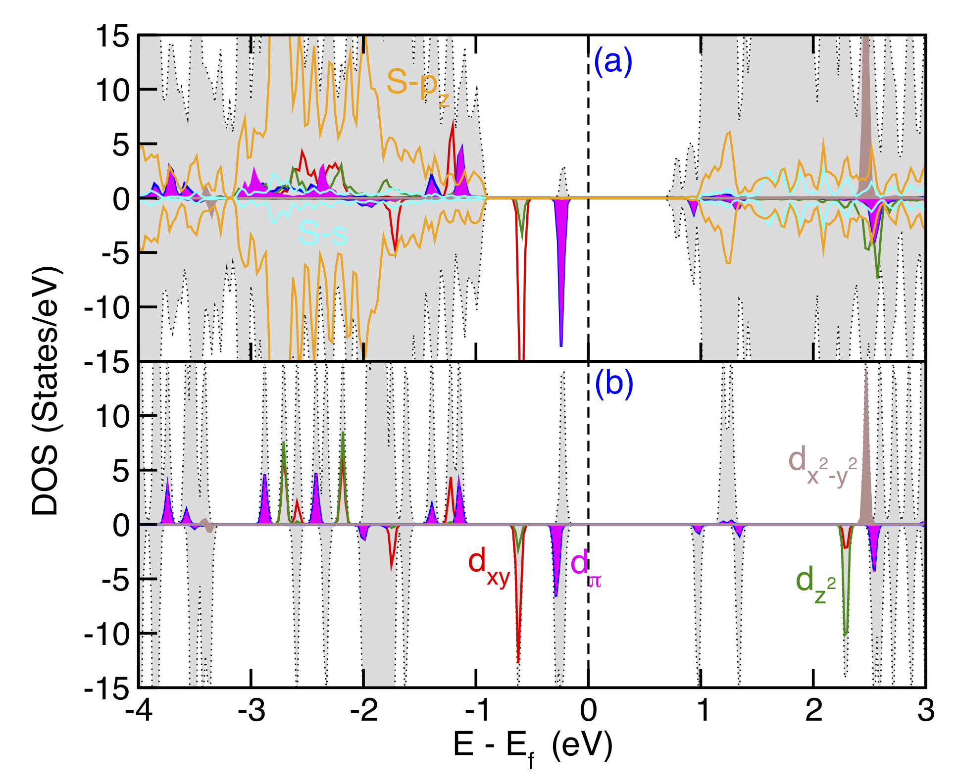
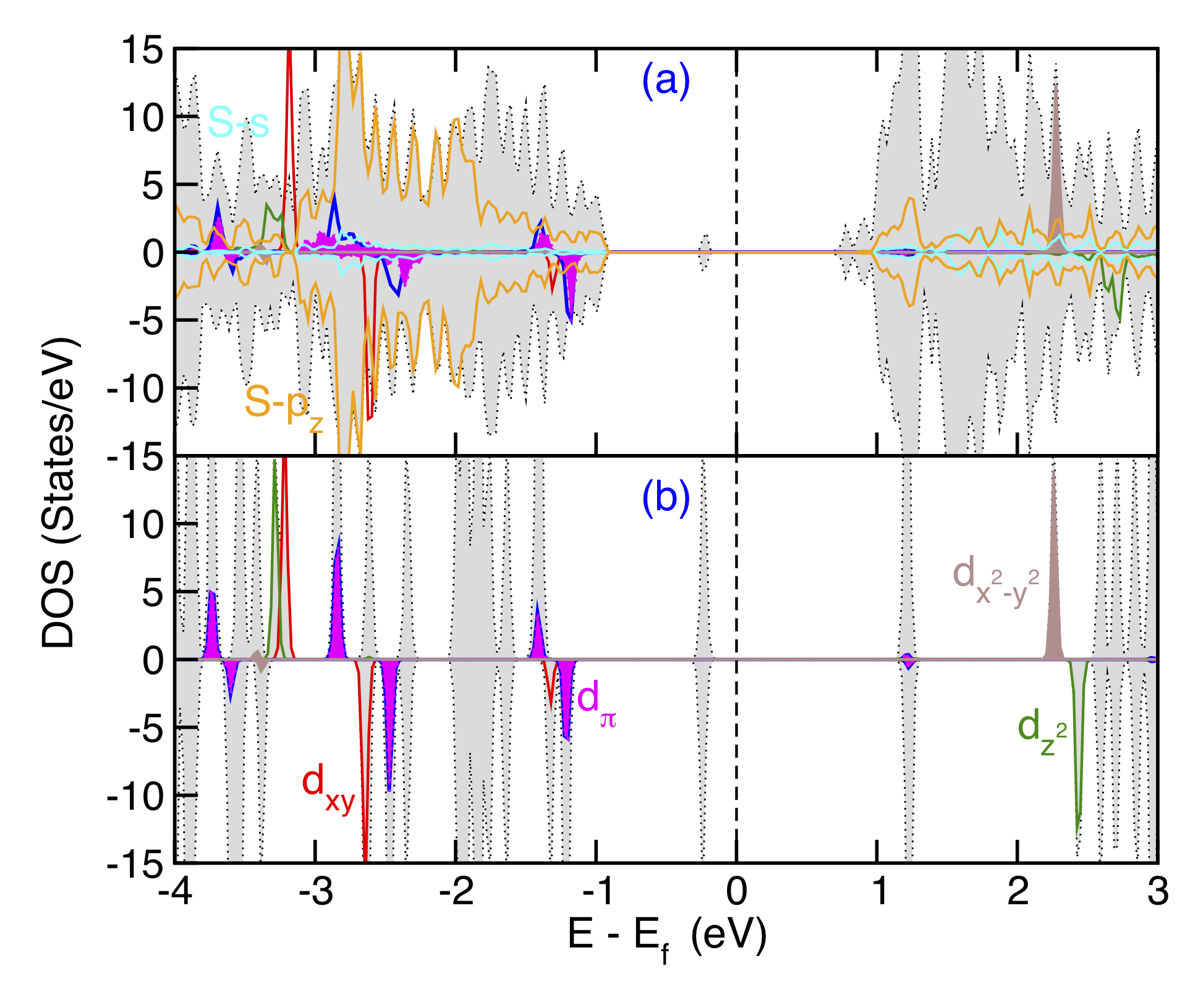
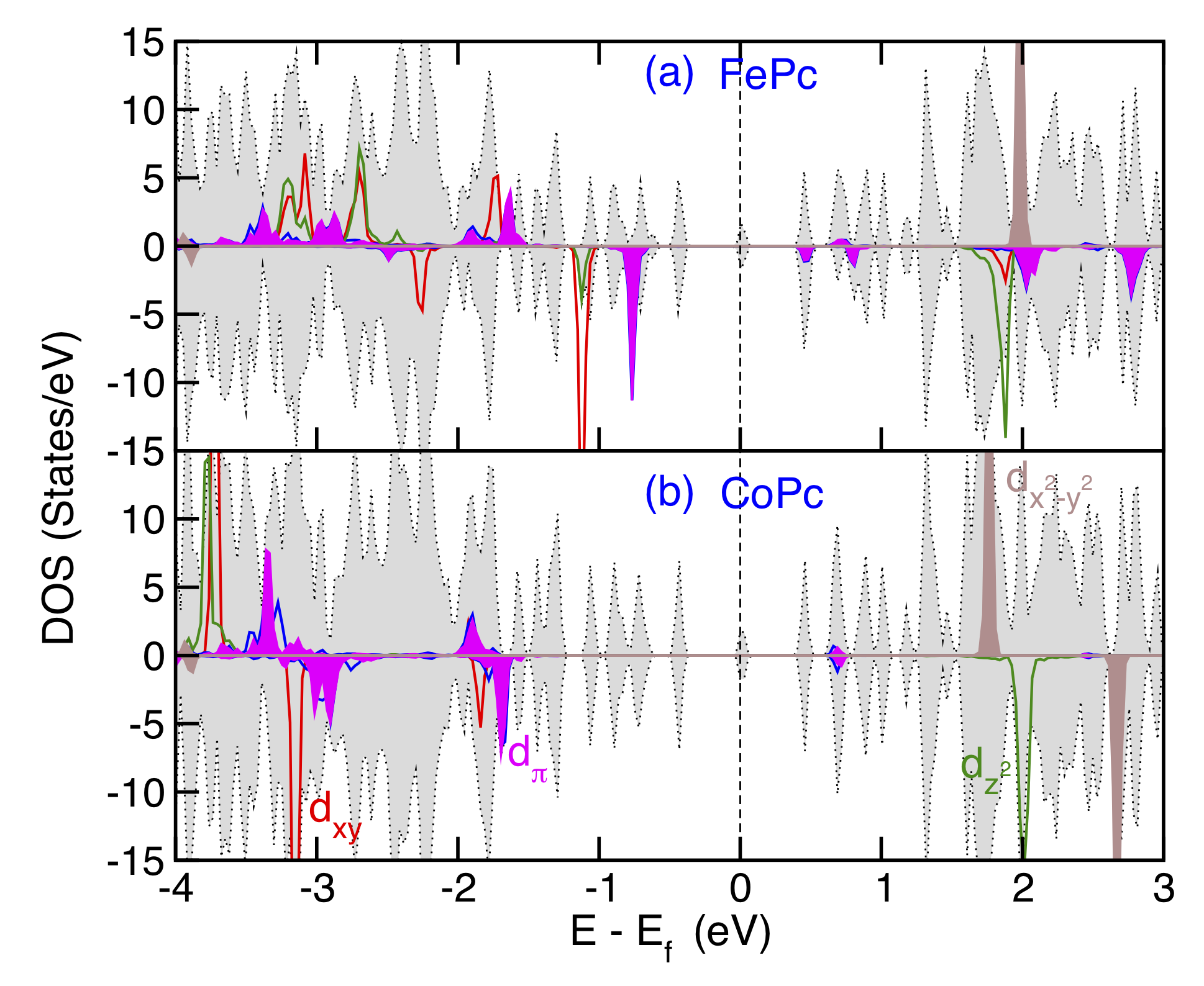
In panel (a) of Fig. 3 and Fig. 4, respectively, we have shown the total density of states for FePc and CoPc physisorbed on 2D \ceMoS2 surface along with the decomposed states of the metal center of the MPc molecules. We have also plotted the projected density of states of and orbitals originating from the top S atom layer of \ceMoS2. In order to compare with the gaseous phase of the molecule, we have also plotted the metal center states along with total density of states of gaseous FePc and CoPc molecule in the panel (b) of the Fig. 3 and Fig. 4 respectively. In Fig. 5(a) and Fig. 5(b) respectively, we have plotted the total density of states of FePc and CoPc physisorbed on graphene surface along with the decomposed states of the metal atom center.
From the analysis of projected density of states, it can be seen that the out-of-plane orbitals of the metal atoms become broaden after physisorption on \ceMoS2 as compared to the gaseous phase (see Fig. 5(a)). These are mainly seen on the occupied out-of-plane orbital as well as and orbitals. These broadenings of orbitals are mainly due to the hybridization between out-of-plane orbitals of the physisorbed molecule and the S- orbitals of top S atoms of \ceMoS2. In case of graphene, a similar broadening can also be seen (see Fig. 5(b)). However, the amount of hybridization is relatively weak which is evident from the smaller physisorption energy and larger vertical distance (see table 2). The total magnetic moments after physisorption on \ceMoS2 and graphene are 2.0 and 1.0 respectively for FePc and CoPc. The majority of magnetic moments are coming from the orbital of the metal atom. The physisorbed FePc has a spin configuration of S=1. S=1 is equivalent to a 231 electronic configurations where orbital has occupancy 2, orbital has occupancy 3 and orbital has occupancy 1. However, for CoPc the spin configuration is S=1/2, which is equivalent to a 241 electronic configurations where orbital has occupancy 2, orbital has occupancy 4 and orbital has occupancy 1. The magnetic moments and the electronic configurations of MPc molecules in the physisorbed situation do not change from the gas phase value significantly. This is because the hybridized orbitals are quite below from the Fermi energy. Thus there are no creation of bonding and anti-bonding orbital and hence no weight transfer. Therefore, the electronic configuration and magnetic moments remain same.
III.2.1 Spin dipole contribution
As mentioned in the introduction, for a low symmetry structure, deformation in the spin densities are expected to be large. These deformed spin densities lead to a large value of the spin dipole moment 7 where 7 is the expectation value of the component of the spin-dipole operator . Bhandary et al. (2011) The discussions of the spin dipole moments are also quite relevant for XMCD measurements, where the measured effective moments contain both spin and spin-dipole moments.
| System | 2 | 7Tz | |
|---|---|---|---|
| FePc@\ceMoS2 | 2.0 | -2.09 | -0.09 |
| CoPc@\ceMoS2 | 1.0 | -1.69 | -0.69 |
| FePc@graphene | 2.0 | -2.05 | -0.05 |
| CoPc@graphene | 1.0 | -1.70 | -0.70 |
| FePc | 2.0 | -1.99 | 0.01 |
| CoPc | 1.0 | -1.70 | -0.70 |
Following the formalism of Oguchi et al. Oguchi and Shishidou (2004), the spin dipole operator can be defined as:
| (2) |
where, is the quadrupolar tensor and can be described as:
| (3) |
Every component of can be written in second quantization form as:
| (4) |
The matrix elements of and are :
| (5) | |||
| (6) |
where, .
To calculate the spin dipole moments, we have followed the method prescribed by Freeman et al. [Ref. Wu and Freeman, 1994] and performed density functional theory calculations including all the above discussed effects. The results of calculated spin dipole moments for MPc gas phase molecules and MPc physisorbed on \ceMoS2 and graphene are tabulated in Table 3. As seen from the table, the calculated values of spin dipole moments are -2.09 and -1.69 for FePc and CoPc physisorbed on monolayer \ceMoS2, respectively. For graphene, the values are -2.05 and -1.70 respectively. From our calculation, it is clear that the values of spin dipole moments (7) are very strong and they are opposite to the spin moment (2). Hence, the effective spin moment defined as = 2 + 7, will be reduced by a huge amount.
Our calculation also indicates that the comparative values of spin dipole moments do not change significantly for both MPc molecules after physisorption on \ceMoS2 or graphene as compared to the gas phase. The values of spin dipole moments depend mainly on the projected occupancies of the orbitals of the metal atom center of MPc molecules. From the detailed analysis of density matrix it can be seen that the occupations of these orbitals do not change significantly in physisorption situation as compared from the gas phase. Hence the changes in spin dipole moments are minimal.
III.2.2 Orbital moments and magnetic anisotropy
As discussed the importance of magneto crystalline anisotropy in the introduction, we have also incorporated the spin-orbit coupling in the Hamiltonian of our DFT calculations to calculate orbital moments and magneto crystalline energy. The magnetic crystalline anisotropy originates from the coupling between lattice and spin. It can be expressed as follows:
| (7) |
where is the spin-orbit coupling Hamiltonian and is the spin orbit coupling constant which can be defined as follows
| (8) |
where is the radial part of the 3d wave function. The value of for Fe2+ and Co2+ have been taken from literature and considered as 49.6 meV and 63.8 meV respectively. Cole Jr and Garrett (1970) Using second order perturbation theory, one can write the spin-orbit contribution to the energy as follows
| (9) |
In the above equation, and denotes the weighted occupied and unoccupied states of Fe/Co orbitals. These occupied and unoccupied states are weighted by the occupation of respective orbitals, . The orbital and spin operators are denoted by L and S. and denote the eigenvalues of occupied and unoccupied stated and this values have been taken from the ab initio calculations. From the equation 9, it is clear that the spin-orbit coupling energy contribution increases when decreases. Therefore the relative placement of the orbitals of the Fe/Co will dictate the energy contribution to the spin-orbit coupling. The relative arrangement of the orbitals can be affected by the physisorption site of the MPc on \ceMoS2 or graphene.
| Easy | |||
|---|---|---|---|
| System | (eV) | axis | |
| FePc@\ceMoS2 | 0.012 | 52 | Out-of-plane |
| CoPc@\ceMoS2 | 0.036 | 75 | In-plane |
| Easy | |||
|---|---|---|---|
| System | (eV) | axis | |
| FePc@graphene | 0.012 | 48.5 | Out-of-plane |
| CoPc@graphene | 0.037 | 76 | In-plane |
| Easy | |||
|---|---|---|---|
| System | (eV) | axis | |
| FePc | 0.012 | 30 | Out-of-plane |
| CoPc | 0.037 | 78 | In-plane |
| Easy | |||
|---|---|---|---|
| System | (eV) | axis | |
| FePc@\ceMoS2 | 0.019 | 103 | Out-of-plane |
| CoPc@\ceMoS2 | 0.028 | 58 | In-plane |
| Easy | |||
|---|---|---|---|
| System | (eV) | axis | |
| FePc@graphene | 0.024 | 107.8 | Out-of-plane |
| CoPc@graphene | 0.030 | 60.2 | In-plane |
| Easy | |||
|---|---|---|---|
| System | (eV) | axis | |
| FePc | 0.026 | 98 | Out-of-plane |
| CoPc | 0.028 | 60 | In-plane |
We have used two different approach to calculate the magneto crystalline energy – i) variational approach implemented in vasp code and ii) 2nd order perturbation approach. We have tabulated the result of these two approaches in table 4 and in table 5 respectively. We have reported the orbital magnetic moments, magnetic anisotropy energies along with the information about the easy axis in table 4 and 5. Both approaches mentioned before gives similar qualitative results. As seen from the table 4, the orbital moments values do not change significantly in the physisorbed systems. The analysis of projected density of states (see Fig. 3, Fig. 4, Fig. 5) indicate that although the orbitals below the Fermi levels are broadened in the physisorbed system compared to the gas phase, the band center remains same . Hence the orbital moments remain almost similar. The relative positions of orbitals of Co metal center in CoPc do not change significantly from gas phase in to the physisorbed phase. Therefore, the transition matrices are similar and hence the magneto crystalline anisotropy energies are similar in values. However, for FePc the values of magneto crystalline anisotropy energies are different from the gas phase as the Fe- orbitals overlapped differently in the unoccupied regions in physisorbed cases. Our results indicate that while for CoPc the easy axis of magnetization is in-plane, the easy axis is out-of-plane for FePc.
III.2.3 Work function
Decoration by the molecules is one of the method to change the surface work function. These changes can enable the use of graphene or \ceMoS2 in designing various different nano-devices. In order to investigate possible change in work function () of the \ceMoS2 and graphene due to the MPc physisorption, we have calculated the work function of the pristine monolayer \ceMoS2, graphene and MPc physisorbed \ceMoS2 and graphene. The work function is defined as the minimum energy required to remove an electron from a material to the vacuum. Hence the work function can be defined as the following,
| (10) |
where, is the self-consistent electrostatic potential in the vacuum far from the surface and is the Fermi energy and is calculated from a ground state self-consistent calculation. Here we have taken the Fermi energy to be the top of valence band. The surface work functions were calculated by applying the Neugebauer-Scheffler dipole correction Neugebauer and Scheffler (1992) for the direction perpendicular to the surface. The electrostatic potential is obtained as function of by averaging the self-consistent potential parallel to the surface, i.e., in the plane. Then the potential is approximated as the value of potential at the vacuum layer where is reaching its asymptotic limit.
| System | (eV) | |
|---|---|---|
| \ceMoS2 (1L) | 5.94 | |
| \ceMoS2 | FePc | 4.94 |
| CoPc | 5.17 | |
| System | (eV) | |
|---|---|---|
| Graphene (1L) | 4.23 | |
| Graphene | FePc | 4.25 |
| CoPc | 4.25 | |
In table 6, we have tabulated the calculated values of for the above mentioned cases. The value of for monolayer graphene is 4.23 eV. This value is quite consistent with previous published result. Kwon et al. (2012) For \ceMoS2, the computed value of is 5.94 eV which is similar to earlier published result. Lanzillo et al. (2015) It is evident from our calculation is that the value of does not change significantly after MPc physisorption on graphene. However, the work function value of \ceMoS2 decreases after MPc physisorption. Hence our calculation shows that it can be possible to tune the of \ceMoS2 by MPc physisorption. Work function dependency on MPc physisorption on \ceMoS2 opens up the possibility of using these materials in electronic and optoelectronic devices.
IV Conclusions
We have performed detailed investigation of electronic and magnetic properties of MPc (M = Fe, Co) physisorption on \ceMoS2 and graphene using density functional theory along with Coulomb correlation for the metal electrons. We have considered various possible physisorption sites both on \ceMoS2 and on graphene to find out energetically most favorable configuration. From our calculation, we have found out that MPc molecules are physisorbed strongly on \ceMoS2 as compared to graphene. The most stable physisorption site on \ceMoS2 is when the metal atom center of the MPc molecules resides on top of S atom. The other physisorption sites have much higher energy ( 0.14 eV). However, on graphene, the physisorption energies are very similar for different physisorption sites. The out-of-plane orbitals of the metal centers hybridize with the out-of-plane orbitals from \ceMoS2 and graphene. The magnetic moment comes from orbital of the metal atom. MPc physisorption reduces the work function of \ceMoS2 by 1 eV whereas it does not change much in the case of graphene. MPc physisorption causes a large spin dipole moment opposite to the spin moment, which can be measured by XMCD experiment. It causes a huge reduction of effective magnetic moments of the system. Our calculations of magnetic anisotropy energies using both variational approach and order perturbation approach indicate no significant changes in the magnetic anisotropy energy values after physisorption of the MPc molecules. An out-of-plane magnetic anisotropy can be observed in the case of FePc whereas for CoPc it is in-plane.
Acknowledgment
SH and BS would like to acknowledge KAW foundation for financial support. In addition, BS acknowledges Carl Tryggers Stiftelse, Swedish Research Council and KOF initiative of Uppsala University for financial support. We are grateful to NSC under Swedish National Infrastructure for Computing (SNIC) and the PRACE-2IP project resource Cy-Tera supercomputer based in Cyprus at the Computation-based Science and Technology Research Center (CaSToRC) and Salomon cluster based in Czech Republic at the IT4Innovations for computer hours. Structural figures are generated using VMD. Humphrey et al. (1996)
References
- Leoni et al. (2011) T. Leoni, O. Guillermet, H. Walch, V. Langlais, A. Scheuermann, J. Bonvoisin, and S. Gauthier, Phys. Rev. Lett. 106, 216103 (2011).
- Wende et al. (2007) H. Wende, M. Bernien, J. Luo, C. Sorg, N. Ponpandian, J. Kurde, J. Miguel, M. Piantek, X. Xu, P. Eckhold, W. Kuch, K. Baberschke, P. M. Panchmatia, B. Sanyal, P. M. Oppeneer, and O. Eriksson, Nature Materials 6, 516 (2007).
- Dediu et al. (2009) V. A. Dediu, L. E. Hueso, I. Bergenti, and C. Taliani, Nature Materials 8, 850 (2009).
- Bhandary et al. (2013a) S. Bhandary, B. Brena, P. M. Panchmatia, I. Brumboiu, M. Bernien, C. Weis, B. Krumme, C. Etz, W. Kuch, H. Wende, O. Eriksson, and B. Sanyal, Phys. Rev. B 88, 024401 (2013a).
- Martinez-Diaz et al. (2010) M. V. Martinez-Diaz, G. de la Torre, and T. Torres, Chem. Commun. 46, 7090 (2010).
- Ishikawa (2010) N. Ishikawa, in Functional Phthalocyanine Molecular Materials, Structure and Bonding, Vol. 135, edited by J. Jiang (Springer Berlin Heidelberg, 2010) pp. 211–228.
- Bogani and Wernsdorfer (2008) L. Bogani and W. Wernsdorfer, Nat. Mater. 7, 179 (2008).
- Liu et al. (2013) L. Liu, K. Yang, Y. Jiang, B. Song, W. Xiao, L. Li, H. Zhou, Y. Wang, S. Du, M. Ouyang, W. A. Hofer, A. H. Castro Neto, and H.-J. Gao, Sci. Rep. 3, 1 (2013).
- Stróżecka et al. (2012) A. Stróżecka, M. Soriano, J. I. Pascual, and J. J. Palacios, Phys. Rev. Lett. 109, 147202 (5pp) (2012).
- Fu et al. (2007) Y.-S. Fu, S.-H. Ji, X. Chen, X.-C. Ma, R. Wu, C.-C. Wang, W.-H. Duan, X.-H. Qiu, B. Sun, P. Zhang, J.-F. Jia, and Q.-K. Xue, Phys. Rev. Lett. 99, 256601 (4pp) (2007).
- Ragoussi et al. (2012) M.-E. Ragoussi, J.-J. Cid, J.-H. Yum, G. de la Torre, D. Di Censo, M. Grätzel, M. K. Nazeeruddin, and T. Torres, Angewandte Chemie International Edition 51, 4375 (2012).
- Antonietta Loi et al. (2003) M. Antonietta Loi, P. Denk, H. Hoppe, H. Neugebauer, C. Winder, D. Meissner, C. Brabec, N. Serdar Sariciftci, A. Gouloumis, P. Vazquez, and T. Torres, J. Mater. Chem. 13, 700 (2003).
- Betti et al. (2010) M. G. Betti, P. Gargiani, R. Frisenda, R. Biagi, A. Cossaro, A. Verdini, L. Floreano, and C. Mariani, The Journal of Physical Chemistry C 114, 21638 (2010), http://dx.doi.org/10.1021/jp108734u .
- Neto et al. (2009) A. H. C. Neto, F. Guinea, N. M. R. Peres, K. S. Novoselov, and A. K. Geim, Rev. Mod. Phys 81, 109 (2009).
- Geim and Novoselov (2007) A. Geim and K. Novoselov, Nat. Mater. 6, 183 (2007), 0702595 [cond-mat] .
- Geim (2009) A. K. Geim, Science 324, 1530 (2009), arXiv:0906.3799 .
- Xie (2016) D. Xie, Chem. Commun. 52, 9418 (2016).
- Kudo and Miseki (2009) A. Kudo and Y. Miseki, Chem. Soc. Rev. 38, 253 (2009).
- Li et al. (2013) Y. Li, Y.-L. Li, C. M. Araujo, W. Luo, and R. Ahuja, Catal. Sci. Technol. 3, 2214 (2013).
- Wang et al. (2012) Q. H. Wang, K. Kalantar-Zadeh, A. Kis, J. N. Coleman, and M. S. Strano, Nat. Nanotechnol. 7, 699 (2012).
- Chou et al. (2013) S. S. Chou, B. Kaehr, J. Kim, B. M. Foley, M. De, P. E. Hopkins, J. Huang, C. J. Brinker, and V. P. Dravid, Angew. Chem., Int. Ed. 52, 4160 (2013).
- Liu et al. (2014a) T. Liu, C. Wang, W. Cui, H. Gong, C. Liang, X. Shi, Z. Li, B. Sun, and Z. Liu, Nanoscale 6, 11219 (2014a).
- Yang et al. (2014) X. Yang, J. Li, T. Liang, C. Ma, Y. Zhang, H. Chen, N. Hanagata, H. Su, and M. Xu, Nanoscale 6, 10126 (2014).
- Haldar et al. (2015) S. Haldar, H. Vovusha, M. K. Yadav, O. Eriksson, and B. Sanyal, Physical Review B - Condensed Matter and Materials Physics 92, 235408 (2015), 1509.01445 .
- Liu et al. (2014b) J.-T. Liu, T.-B. Wang, X.-J. Li, and N.-H. Liu, J. Appl. Phys. 115, 193511 (2014b).
- Jing et al. (2014) Y. Jing, X. Tan, Z. Zhou, and P. Shen, J. Mater. Chem. A 2, 16892 (2014).
- Choudhury et al. (2017) P. Choudhury, L. Ravavarapu, R. Dekle, and S. Chowdhury, The Journal of Physical Chemistry C 121, 2959 (2017).
- Kandpal et al. (2012) H. C. Kandpal, K. Koepernik, and M. Richter, Phys. Rev. B 86, 235430 (2012).
- Porter and Stroud (2012) C. D. Porter and D. Stroud, Phys. Rev. B 85, 235452 (2012).
- Lisi et al. (2015) S. Lisi, P. Gargiani, M. Scardamaglia, N. B. Brookes, V. Sessi, C. Mariani, and M. G. Betti, The Journal of Physical Chemistry Letters 6, 1690 (2015).
- Šipr et al. (2009) O. Šipr, J. Minár, and H. Ebert, EPL (Europhysics Letters) 87, 67007 (2009).
- Bhandary et al. (2011) S. Bhandary, S. Ghosh, H. Herper, H. Wende, O. Eriksson, and B. Sanyal, Physical Review Letters 107, 257202 (2011).
- Stepanow et al. (2010) S. Stepanow, J. Honolka, P. Gambardella, L. Vitali, N. Abdurakhmanova, T.-C. Tseng, S. Rauschenbach, S. L. Tait, V. Sessi, S. Klyatskaya, M. Ruben, and K. Kern, Journal of the American Chemical Society 132, 11900 (2010).
- Herper et al. (2013) H. C. Herper, M. Bernien, S. Bhandary, C. F. Hermanns, A. Krüger, J. Miguel, C. Weis, C. Schmitz-Antoniak, B. Krumme, D. Bovenschen, C. Tieg, B. Sanyal, E. Weschke, C. Czekelius, W. Kuch, H. Wende, and O. Eriksson, Physical Review B 87, 174425 (2013).
- Kresse and Furthmüller (1996) G. Kresse and J. Furthmüller, Phys. Rev. B 54, 11169 (1996).
- Perdew et al. (1996) J. P. Perdew, K. Burke, and M. Ernzerhof, Phys. Rev. Lett. 77, 3865 (1996).
- Perdew et al. (1997) J. P. Perdew, K. Burke, and M. Ernzerhof, Phys. Rev. Lett. 78, 1396 (1997).
- Dudarev et al. (1998) S. L. Dudarev, G. A. Botton, S. Y. Savrasov, C. J. Humphreys, and A. P. Sutton, Phys. Rev. B 57, 1505 (1998).
- Solovyev et al. (1994) I. V. Solovyev, P. H. Dederichs, and V. I. Anisimov, Phys. Rev. B 50, 16861 (1994).
- Anisimov et al. (1997) V. I. Anisimov, F. Aryasetiawan, and A. I. Lichtenstein, Journal of Physics: Condensed Matter 9, 767 (1997).
- Wehling et al. (2011) T. O. Wehling, A. I. Lichtenstein, and M. I. Katsnelson, Physical Review B 84, 235110 (2011).
- Eelbo et al. (2013) T. Eelbo, M. Waśniowska, P. Thakur, M. Gyamfi, B. Sachs, T. O. Wehling, S. Forti, U. Starke, C. Tieg, A. I. Lichtenstein, and R. Wiesendanger, Physical Review Letters 110, 136804 (2013).
- Tkatchenko and Scheffler (2009) A. Tkatchenko and M. Scheffler, Phys. Rev. Lett. 102, 073005 (2009).
- Bhandary et al. (2013b) S. Bhandary, O. Eriksson, and B. Sanyal, Scientific Reports 3 (2013b).
- Oguchi and Shishidou (2004) T. Oguchi and T. Shishidou, Physical Review B 70, 024412 (2004).
- Wu and Freeman (1994) R. Wu and A. Freeman, Physical Review Letters 73, 1994 (1994).
- Cole Jr and Garrett (1970) G. Cole Jr and B. Garrett, Inorganic Chemistry 9, 1898 (1970).
- Neugebauer and Scheffler (1992) J. Neugebauer and M. Scheffler, Phys. Rev. B 46, 16067 (1992).
- Kwon et al. (2012) K. C. Kwon, K. S. Choi, and S. Y. Kim, Adv. Funct. Mater. 22, 4724 (2012).
- Lanzillo et al. (2015) N. A. Lanzillo, A. J. Simbeck, and S. K. Nayak, J. Phys. Condens. Matter 27, 175501 (2015).
- Humphrey et al. (1996) W. Humphrey, A. Dalke, and K. Schulten, J. Molecular Graphics 14, 33 (1996).