Joint Relay Selection and Power Allocation in Large-Scale MIMO Systems with Untrusted Relays and Passive Eavesdroppers††thanks: This work was supported by the INSF and contract number 94023761. A. Kuhestani and A. Mohammadi are with Department of Electrical Engineering, Amirkabir University of Technology, Tehran, Iran (emails: a.kuhestani@aut.ac.ir; abm125@aut.ac.ir).††thanks: M. Mohammadi is with the Faculty of Engineering, Shahrekord University, Shahrekord, Iran (e-mail: m.a.mohammadi@eng.sku.ac.ir).
Abstract
In this paper, a joint relay selection and power allocation (JRP) scheme is proposed to enhance the physical layer security of a cooperative network, where a multiple antennas source communicates with a single-antenna destination in presence of untrusted relays and passive eavesdroppers (Eves). The objective is to protect the data confidentially while concurrently relying on the untrusted relays as potential Eves to improve both the security and reliability of the network. To realize this objective, we consider cooperative jamming performed by the destination while JRP scheme is implemented. With the aim of maximizing the instantaneous secrecy rate, we derive a new closed-form solution for the optimal power allocation and propose a simple relay selection criterion under two scenarios of non-colluding Eves (NCE) and colluding Eves (CE). For the proposed scheme, a new closed-form expression is derived for the ergodic secrecy rate (ESR) and the secrecy outage probability as security metrics, and a new closed-form expression is presented for the average symbol error rate (SER) as a reliability measure over Rayleigh fading channels. We further explicitly characterize the high signal-to-noise ratio slope and power offset of the ESR to highlight the impacts of system parameters on the ESR. In addition, we examine the diversity order of the proposed scheme to reveal the achievable secrecy performance advantage. Finally, the secrecy and reliability diversity-multiplexing tradeoff of the optimized network are provided. Numerical results highlight that the ESR performance of the proposed JRP scheme for NCE and CE cases is increased with respect to the number of untrustworthy relays.
Index Terms:
Physical-layer security, untrusted relay, joint relay selection and power allocation.I Introduction
Large-scale multiple-input multiple-output (MIMO) system as a promising solution of the fifth-generation (5G) wireless communication networks provides significant performance gains in terms of energy saving and spectral efficiency [1], [2]. This new technology deploys simple coherent processing methods, e.g., maximum ratio transmission (MRT) across arrays of hundreds of or even more antennas at base station (BS) and supports tens of or more mobile users (MUs) [1]–[3]. An attractive feature of large-scale MIMO systems is that they offer a significant security improvement compared to a conventional MIMO systems, as with large-scale multiple antennas (LSMA) at the BS, a narrow directional beam can be radiated toward the desired terminal. Accordingly, the received signal power at the desired terminal is several orders of magnitude higher than that at any non-coherent passive eavesdropper (Eve) [3]111It is worth noting that in contrast to passive eavesdropping, an active Eve may cause pilot contamination at the BS and pose more serious security problem to the network [4], [5].. However, the security benefits of LSMA systems are severely hampered in cooperative networks, where the intermediate nodes may be potential Eves [6].
Owing to the broadcast nature of wireless communication, the information transmission between legitimate users can be simply captured by Eves. Accordingly, physical layer security (PLS) as a promising approach to enhance the confidentiality of wireless communications has attracted a lot of interest [7], [8]. Physical layer secure transmission is provisioned by intelligently exploiting the time varying properties of fading channels, instead of relying on conventional cryptographic techniques [7]. Among the proposed PLS solutions, cooperative relaying, cooperative jamming (CJ) and a mixed of these two techniques have recently attracted a great deal of interest [9]–[18]. Cooperative relaying can enhance the PLS through implementing distributed beamforming or opportunistic relaying (OR) [9], [10]. In contrast to distributed beamforming that suffers from high complexity due to the need of large overhead, OR imposes low system overhead by choosing only one relay which offers the best secrecy performance for the network [10]. As a complementary approach, CJ schemes can also be implemented by the network’s nodes to transmit jamming signals towards the Eves in order to degrade the received signal-to-noise ratio (SNR) at the Eves [11]–[18]. This goal can be achieved through applying the following three methods: 1) Source-based jamming [11], [12] in which the source transmits a mixed signal carrying the information signal and the jamming signal, 2) Friendly jammer-based jamming [12]–[15] in which a relay [12]–[14] or an external friendly jammer (FJ) [15] contributes to provide confidential communication, and 3) Destination-based CJ (DBCJ) [16]–[24], in which the destination itself contributes to degrade the received signal at an external Eve [16]–[18] or at a helper intermediate node who may act as an Eve [6]. Among the presented methods, the DBCJ policy can be implemented simply compared to the first and second methods, where the destination performs self-interference cancellation with regard to its prior information of jamming signal. Contrary to DBCJ, for the first and second methods, the destination must be perfectly aware of the pre-defined jamming signal, while it is unknown for the Eves. This a priori known jamming signal, generated by using some pseudo-random codes or some cryptographic signals, is hard to implement and transfer to the destination confidentially. Transferring this known jamming signal from the source to destination imposes more challenges to the network, when an untrusted relay collaborates for data transmission.
From a perspective of security, a trusted relay can friendly assist to protect the confidential message from being eavesdropped by illegitimate nodes, while an untrusted relay may intentionally overhear the information signal when relaying. In some communication networks, an untrusted relay may collaborate to provide a reliable communication [6]. This scenario occurs in large-scale wireless systems such as heterogeneous networks, device-to-device (D2D) communications and Internet-of-things (IoT) applications [5], where confidential messages are often retransmitted by multiple intermediate nodes. It is therefore necessary to answer this question that whether exploiting the untrusted relay is still beneficial compared with direct transmission (DT) and if so, what the appropriate relaying strategy should be.
To achieve a positive secrecy rate in untrusted relaying networks, the DBCJ policy was first introduced in [6]. Then several recent works have investigated the performance of the DBCJ policy in presence of a single [19], [20] or multiple [21]–[24] untrusted relays. Specifically, the secrecy performance of DBCJ with optimal power allocation (OPA) in presence of an untrusted amplify-and-forward (AF) relay investigated in [19] and then comprehensively studied in [20]. Taking into account non-colluding untrusted relaying, the authors in [21]–[23] derived lower bound expressions for the ergodic secrecy rate (ESR) performance in the absence [21], [22] or presence [23] of source jamming. The researchers in [21]–[23] indicate that increasing the number of untrustworthy relays degrades the ESR in contrast to the case of trustworthy relays. To be specific, the authors in [22] found that the diversity order of OR is restricted to unity independent of the number of untrusted relays. All the aforementioned works [21]–[24] investigated the cooperative untrusted relaying networks in absence of passive Eves and without considering achievable secrecy rate optimization.
While the recent literature [19] presented a solid work for OPA in presence of a single untrusted relay, the impact of OPA on a more realistic cooperative network with multiple untrusted relays and passive Eves has not been studied yet. In this paper, motivated by the recent literature on LSMA-based relaying systems [1], [2], [5], [19], [26], [27], we present a comprehensive research to improve the PLS of cooperative networks in presence of untrusted relays and passive Eves222Henceforth, we interchangeably use the terms ‘passive Eve’ and ‘Eve’.. Along this line, we consider a new cooperative network consisting of a large-scale MIMO source, a destination, multiple non-colluding untrusted AF relays [21]–[24], and multiple non-colluding Eves (NCE) [10], [28] who hide their existence in the network. In contrast to vast studies on the secrecy performance of untrusted relaying networks [19]–[24], we take into account joint relay selection and power allocation (JRP) in our network by considering the information leakage in the second phase of transmission. We further investigate a worst-case scenario, where passive Eves may collaborate together to maximize the total received SNR. Toward this end, we consider the scenario that the maximal ratio combining (MRC) is performed over all the received signals from the source and the selected relay to perform more harmful attacks. This event is referred to as colluding Eves (CE) [28], [29]. As a benchmark, we next study the conventional DT dispensing with the relays to compare with the proposed JRP transmission policy. In contrast to [30], in which DT policy with transmit antenna selection is analyzed for MIMO wiretap channels, we utilize the simple MRT beamformer [2] in our proposed DT policy to maximize the received SNR at the intended receiver. Furthermore, different from [30] that considered one multiple antennas Eve, we consider two cases of NCE and CE. Therefore, our system model and the related analysis are completely different compared with [30].
The main contributions of the paper are summarized as follows:
-
1.
We develop a JRP scheme to maximize the instantaneous secrecy rate of the network for both NCE and CE cases. Our findings highlight that the large-scale MIMO approach as a powerful mathematical tool offers a new simple relay selection criterion. The proposed criterion only requires the channel state information (CSI) of the relays-destination links.
-
2.
Based on the proposed JRP scheme, new closed-form expressions are derived for the probability of positive secrecy rate and the ESR of NCE and CE cases over Rayleigh fading channels. Furthermore, new compact expressions are derived for the asymptotic ESR. Our asymptotic results highlight that the probability of positive secrecy transmission tends to one for the optimized JRP scheme as the number of relays grows. Moreover, we find that the ESR performance improves as increases. We further characterize the high SNR slope and power offset of the ESR to highlight the impact of system parameters on the ESR performance.
-
3.
For the proposed JRP scheme, new closed-form expressions are derived for the secrecy outage probability (SOP) of both NCE and CE cases over Rayleigh fading channels. In order to shed insights into the system performance, new simple expressions are derived for the SOP in the high SNR regime. Our asymptotic results highlight that the proposed JRP scheme enjoys the diversity order of . Next, the secrecy diversity-multiplexing trade-off (DMT) is examined to express the trade-off between the error probability and the data rate of the proposed JRP scheme.
-
4.
For DT policy, a new tight lower bound is derived for the ESR of NCE and CE cases. We also derive a new closed-form expression for the SOP of those cases. Our results show that the high SNR slope and the secrecy diversity order of this transmission policy are zero.
-
5.
To illustrate the reliability of the network, we calculate the average symbol error rate (SER) as the performance measure. New exact and asymptotic closed-form expressions are derived for the SER performance of the proposed JRP scheme over Rayleigh fading channels. Our results highlight that the proposed scheme offers the diversity order of . We further determine the reliability DMT of the proposed scheme.
The remainder of this paper is organized as follows. In Section II we present the system model and preliminaries. Next, in Section III, the relay selection criterion is introduced and the related OPA is evaluated. Performance metrics are evaluated in Section IV. Numerical results are presented in Section V, followed by conclusions in Section VI.
Notation: We use bold lower case letters to denote vectors. and denote the Identity matrix and the zeros matrix, respectively. and denote the Euclidean norm and conjugate transpose operator, respectively; stands for the expectation over the random variable x; denotes the probability; and denote the probability density function (pdf) and cumulative distribution function (cdf) of the random variable (r.v.) , respectively; denotes a circularly symmetric complex Gaussian r.v. with mean and variance ; , and are the exponential integral [31, Section (8.21)], the Q-function [31, Section (8.25)] and the psi function [31, Section (8.25)], respectively. and stands for the maximum value. is the smallest integer that is larger than or equal to .
II System Model
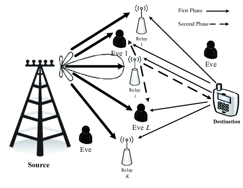
We consider a cooperative LSMA-based network consisting of one multiple antennas source equipped with an array of antennas, one single-antenna destination, single-antenna untrusted AF relays and single-antenna passive Eves333The presence of multiple Eves in a wireless network may be a realistic scenario in which the malicious nodes act as harmful attackers to the authorized terminals [5], [29]. as depicted in Fig. 1. The untrusted relays in our network are so-called semi-trusted, i.e., they are trusted at the service level while they are untrusted at the data level444The service level trust conveys this concept that the accurate CSI of the communication links can be given to the source through relay’s cooperation, and the relay retransmits the received information signal toward the destination. However, this collaboration is untrustworthy at the data level, i.e., the relay may decipher the confidential information from their received signal. [6]. All the passive Eves are randomly located around the source, the relay nodes and the destination, and they hide their existence in the network. We mention that, in this paper, the term “malicious node” includes both the untrusted relays and passive Eves. We further assume that each node operates in a half-duplex mode. Based on time division duplexing (TDD) operation, the source obtains downlink CSI through uplink training. Then the acquired CSI is used to generate the low implementation complexity MRT precoding matrix [26].
We assume that the untrusted relays extract the information signal solely based on its own observation and they adopt selection combining (SC) [23], while relying on the Eves’ behavior, the following two eavesdropping scenarios are considered in our work:
-
1.
Non-colluding eavesdroppers case: In this case, each passive Eve individually overhears the information signal without any collaboration with other Eves. For this case, we assume SC is applied at the Eves. As will be validated via numerical examples, the presented analysis can still be utilized for the case of MRC at the malicious nodes.
-
2.
Colluding eavesdroppers case: In this case, all the passive Eves can connect to a data center to share their information, leading to extract more information. For this case, we assume MRC technique is applied at the Eves to enhance the intercept probability. This case can be considered as a worst-case scenario from the security viewpoint [28].
Some additional assumptions and definitions are as follows:
-
•
Complex Gaussian channel vector from the source to the malicious node : .
-
•
Complex Gaussian channel vector from the source to the destination: .
-
•
Complex Gaussian channel from the selected relay to the destination: .
-
•
Complex Gaussian channel from the selected relay to the malicious node : .
-
•
All the channels satisfy the reciprocity theorem [21].
-
•
The additive white Gaussian noise (AWGN) at each receiver ,, is a zero-mean complex Gaussian r.v. with variance .
-
•
The total transmit power of each phase is limited by . One practical reason is the impact of co-channel interference between adjacent networks which should be taken into account in network design.
-
•
is the transmit SNR of the system.
-
•
, , , , and , .
-
•
, , , and .
In the following, we describe two transmission policies adopted in this paper to establish the PLS in our considered network; namely DBCJ policy and DT policy.
II-A DBCJ Policy
In some communication networks, the direct channel gain between the source and destination may be so weak when the source and destination are located far apart or within heavily shadowed areas. In this condition, cooperative relaying offers a promising solution. This scenario has been extensively implemented in most previous works [10], [12]–[14], [18], where the source and relays pertain to a group, while the destination and passive Eves are placed in another group. Some networks including this scenario are the mobile ad-hoc networks (MANETs) [9], the LTE cellular systems [9], [14] and the IoT network [5], [25]. The aim of DBCJ policy is to deteriorate the received signal at the malicious nodes and to not allow them to decipher the information signal.
Now, we proceed to highlight the necessity of adopting jamming signal in our relay-aided network. Toward this end and for the first step, we investigate the conventional AF relaying scheme in which CJ is not utilized for data transmission. Since the selected relay itself is a curious node, the instantaneous secrecy rate is given by [21]
| (1) |
According to the fact that [21], one can easily conclude that . This result indicates that the achievable secrecy rate of the conventional untrusted relaying scheme without employing CJ is zero. Therefore, a jamming signal must be sent to degrade the received signal at the untrusted relay. In this paper, due to the simplicity of DBCJ policy compared with source-based jamming and FJ-based jamming, we adopt the DBCJ policy to provide perfect secure transmission. It is worth noting that the analysis in this paper can be simply extended to the case of utilizing an external FJ [15].
Under DBCJ policy, since the nodes operate in a half-duplex mode, the direct link between the source and destination is missed. The whole transmission is performed based on a time division multiple-access (TDMA) protocol including the broadcast phase (first phase) and the relaying phase (second phase). During the first phase, while the source transmits the information signal with power , the destination concurrently radiates the artificial noise with power , where is the power allocation factor. It is worth noting that this power allocation scheme provides insights for the power allocation of the source and destination. This power allocation approach has been exploited in several works for both performance analysis and network optimization design [10], [19]–[21], [23]. During the second phase, the selected relay normalizes its received signal and forwards it with power . Finally, the destination decodes the source information by subtracting the self-interference signal. Note that due to the broadcast nature of wireless communication, the signal transmitted in both the phases could be eavesdropped. In this paper, contrary to most recent literature in multiple untrusted relays [21]–[24] that ignored the information leakage in the second phase of transmission, we consider a more realistic scenario. In our considered scenario, the malicious nodes intercept the transmissions of both the source and the selected relay and then try to capture the information.
Denoting and as the information signal and the jamming signal, respectively, the received signal at the malicious node () in first phase can be expressed as
| (2) |
where represents the MRT beamformer at the source and () indicates the index of the selected relay . In the second phase, the relay amplifies its received signal by an amplification factor of
| (3) |
and broadcasts the message . During the second phase, all the malicious nodes hear the signal diffused by . Thus, the received signal at the malicious node () can be expressed as
| (4) |
Furthermore, at the destination, after performing self-interference cancellation, the corresponding signal is given by
| (5) |
Based on (2), the received signal-to-interference-and-noise-ratio (SINR) at the selected relay and the SINR at the malicious node during the first phase of transmission are respectively, given by
| (6) |
By substituting (2) into (4), the received SINR at the malicious node during the second phase can be expressed as
| (7) |
Moreover, by invoking (5), the SINR at the destination can be obtained as
| (8) |
The instantaneous secrecy rate corresponding to the selected relay can be expressed as [6]
| (9) |
where is the amount of information leaked to the malicious nodes. In case of NCE, the information leakage is given by
| (10) |
Moreover, the information leakage for CE case is given by [28], [29]
| (11) |
where information leakages 1 and 2 describe the information leakage for untrusted relays and passive Eves, respectively.
Remark 1: In practical cooperative networks, e.g., an ultra-dense heterogeneous wireless network, both trusted and untrusted relays exist. In such a network, to combat the potential security attacks from untrusted relays, reliable relay authentication techniques are implemented, i.e., the network needs to discriminate between the trusted and untrusted relays and then adopts the suitable secure transmission policy. The authentication can be accomplished by traditional key-based cryptographic methods or new physical layer authentication (PLA) methods [32], [33]. A novel technique to implement the PLA is the multi-attribute multi-observation (MAMO) technique [33] in which the joint verification of the received signal strength indicator (RSSI) and the hardware imperfections of the transceivers are exploited to authenticate the relay nodes. PLA can also be implemented based on this feature that the device-dependent hardware impairment in-phase/quadrature (I/Q) imbalance related to the reception and transmission of the relays is unique [32].
II-B DT Policy
In DT policy, when the source transmits the information signal to the destination, all the relays and the Eves listen. Accordingly, the received SNR at the malicious node and the SNR at the destination are respectively, represented by
| (12) |
where . In (12), follows from the law of large numbers [34] due to large . Applying the Lindeberg-Levy central limit theorem [34], the r.v. can be approximated as . It is worth pointing out that is very well approximated as a Gaussian r.v. even for small [35]. Therefore, can be considered as an exponential r.v. with mean .
III Joint Relay Selection and Power Allocation
In this section, we first introduce the optimal relay selection scheme. Then motivated by the LSMA [1], [2], our proposed JRP scheme is presented for both NCE and CE cases.
Let denote the index of the best selected relay. A relay that maximizes the instantaneous secrecy rate is selected as
| (14) |
The optimal relay selection criterion (14) requires the CSI of both hops and all inter-relay channels. Therefore, it is rather complicated to be implemented in practice, especially when the number of source antennas and the number of relays are large. To alleviate this issue, motivated by LSMA at the source, we will propose a simple relay selection criterion for both NCE and CE cases.
III-A Non-colluding Eavesdroppers
For NCE case, based on (10), we need to find the maximum received SINR at the malicious nodes. Due to deploying an LSMA at the source and by leveraging the Cauchy-Schwarz inequality, in (6) can be upper bounded by
| (15) |
where represents the power allocation factor related to NCE case. Furthermore, in (7) can be upper bounded by
| (16) | |||||
According to (6), (15) and (16), the information leakage in (10) is simplified as . As such, the instantaneous secrecy rate in (9) is simplified as
| (17) |
Let . Notably . Therefore, for OPA , where is the OPA factor corresponding to NCE case. Therefore, the operator in (17) can be dropped. For NCE case, we have the following key
result.
Proposition 1: For a large number of antennas at the source, the function is a quasiconcave function of in the feasible set and the optimal solution is given by
| (18) |
Proof: By substituting the expressions (6) and (8) into (17), forming the function , and then taking the first derivative of it with respect to , we obtain
| (19) |
where , and . For a large number of antennas at the source, , the coefficients are simplified as , and . By solving , the single feasible solution is obtained as (18). Since , we conclude that is a quasiconcave function in the feasible set.
Thanks to the LSMA at the source, by applying the law of large numbers [34], we have . Therefore, the optimal solution (18) that requires the CSI of both hops can be further simplified as
| (20) |
The proposed OPA factor in (20) requires only the CSI of the selected relay-destination link and the statistical mean of the source-selected relay link.
By substituting (20) into (6) and (8), we obtain
| (21) |
Therefore, by using (21), the instantaneous secrecy rate in (9) can be rewritten as
| (22) |
The interesting result in (22) indicates that the instantaneous secrecy rate only depends on the transmit SNR and the relay-destination link. As a consequence, the high complexity relay criterion (14) can be approximated as
| (23) | |||||
The proposed relay selection criterion in (23) requires only the relays-destination channel gains and hence, enjoys from low complexity and energy consumption. Furthermore, the relay selection scheme in (23) can be easily implemented using the distributed timer technique in [36].
In practice, the proposed JRP scheme can be implemented as follows: Before data transmission, the relays are scheduled to transmit pilot symbols [26]. Using the pilots, the source and the destination can estimate their channels. Then according to (23), the destination computes the strongest link between itself and the relays and hence, the relay index is selected. Afterward, the destination broadcasts and pilot symbols to estimate the destination-relay link. Then the relay forwards a quantized version of the estimated destination-relay to the source ( bits). Finally, both the source and destination tune their optimal transmit power to start communication. Accordingly, the overall overhead required for broadcasting is equal to bits.
III-B Colluding Eavesdroppers
For CE case, the Eves jointly try to decode the information signal based on MRC processing and hence, the amount of overheard information increases. To tackle this problem, more power should be dedicated to the destination to confuse the Eves compared to in (18) and less power to the source to transmit the information signal. Based on this, , where denotes the OPA factor for CE case. Therefore, in (7) can be approximated as
| (24) |
where follows from the high SNR assumption. The interesting result in (24) expresses that the amount of information leakage to the malicious nodes in the second phase of transmission is approximately the same as the amount of information leaked to the selected relay in the first phase. Based on this new result and given this fact that, the received signal by the malicious nodes in the second phase of transmission is a degraded version of the emitted signal by the selected relay, in (11) is changed to
| (25) |
For the sake of tractability, according to the fact that , and in (6) can be rewritten as
| (26) |
By substituting (26) into (25), we obtain
| (27) |
where . Following the same steps as in Proposition 1, at the high SNR regime, the OPA factor corresponding to CE case can be obtained as
| (28) |
We can conclude from (28) that by increasing the number of Eves, the most amount of the total power is assigned to the destination to inject jamming signal.
Remark 2: In practice, often may not be feasible to achieve the CSI of passive Eves. Based on this practical issue, we consider a scenario, where only the second order statistics related to the Eves’ are available which is a common assumption in the literature [10], [13], [14], [18]. Furthermore, for mathematical simplicity, we assume that the relaying and eavesdropping channels are independent and identically distributed, i.e., for relaying channels with , we consider and , and for eavesdropping channels with , we consider and [9], [13], [14].
Here, we consider the case with large number of passive Eves. As will be observed in numerical examples, the analysis are valid even for moderate number of Eves. Based on the law of large numbers and since the first and the second hops are independent, we have
| (29) |
where we used [31, Eq. (3.352.4)]. By substituting (III-B) into in (28) and then substituting into (27) and (8), we obtain
| (30) |
By substituting and in (30) into (9), the instantaneous secrecy rate is obtained. Accordingly, we find that the optimal relay selection scheme corresponding to the maximum achievable secrecy rate needs the excessive implementational overhead. The optimal relay selection based on both hops is out of the scope of this paper. As such, we adopt the suboptimal simple relay selection scheme proposed for NCE case in (23). We mention that since the second hop has a dominant impact on quantifying the received SNR at the destination, the relay selection criterion in (23) can be considered as a suboptimal criterion to enhance the secrecy rate. Moreover, in case of very LSMA at the source, the suboptimal relay selection criterion in (23) will be the near-optimal one.
For the selected relay with the relay selection criterion in (23) and with very LSMA at the source, we can use the well-known approximation of minimum mean square error (MMSE) estimator as follows [1], [37]
| (31) |
where [31] is Euler’s constant. In (III-B), follows from the fact that the two-hops are independent and follows from evaluating and . For the first case, , we have
| (32) |
where the last equality follows from using the cdf of which can be obtained based on order statistics [34]
| (33) | ||||
| (34) |
where denotes the cardinality of the -th non-empty subcollection of the relays, and the last expression follows from applying the binomial expansion theorem. For the second case , we used Lemma 2.9 in [38]
| (35) |
Therefore, by substituting (III-B) into (30), we arrive at
| (36) |
We conclude from (36) that the constant value increases by increasing the number of Eves in the network. By equipping the source with very LSMA , this information leakage tends to the same as NCE case.
Comparing (21) for NCE and (36) for CE, we can define the new parameter to integrate the performance analysis for NCE and CE cases. Based on this definition, we have
| (37) |
where for NCE case and for CE case.
Remark 3: Both the network power optimization and performance analysis presented in this paper, can be routinely extended to the scenario that the untrusted relays and passive Eves collaboratively decode the information signal based on MRC technique.
Remark 4: According to the results in (15) and (24), the received SNR at the malicious nodes in the second phase of transmission is more than that one in the first phase of transmission. Therefore, when SC is adopted at the malicious nodes, and all of them cooperate to decode the information signal, the network power optimization and performance analysis are similar to the NCE case.
IV Performance Analysis
In this section, we derive new closed-form expressions for the probability of positive secrecy rate, the ESR and the SOP as the metrics of security and the SER as the reliability measure. Both the proposed JRP scheme (which is based on DBCJ policy) and the DT policy are studied.
IV-A Probability of Positive Secrecy Rate
In this section, we proceed to derive the probability of positive secrecy rate for the proposed DBCJ and DT policies.
DBCJ Policy: By substituting (37) into (9) and using the proposed relay selection criterion in (23), the probability of positive secrecy rate can be expressed as
| (38) |
where follows from substituting (33). It can be concluded from (IV-A) that, the proposed JRP is not efficient when the average transmit SNR of the second hop (which is a function of the transmit SNR and the distance-dependent channel gain ) is low. This observation is not surprising, because when the DBCJ policy is adopted, due to the half-duplex operation of the nodes, the direct link between the source and destination is vanished. As such, the destination only relies on the second hop to receive the information signal form the source. Consequently, the reliability of confidential communication is degraded when the relays are far from the destination or the transmit SNR is low. In the high SNR regime, (IV-A) is simplified as
| (39) |
We deduce from (39) that the probability of positive secrecy rate approaches one as the transmit SNR or the number of relays increases. The reason is that as grows, the occurrence probability of a stronger channel between relays and the destination increases and thus, approaches one.
DT Policy: For this policy, we will study the NCE case and CE case separately, below.
IV-A1 NCE Case
In this case, by combining (9), (10) and (12), the probability of positive secrecy rate can be obtained as
| (40) |
where the last expression follows from the fact that can be approximated as an exponential r.v., as mentioned in Section II-B. This result reveals that as the number of malicious nodes goes to infinity. Furthermore, one can obtain as , which is an intuitive observation, since by increasing , the source with an LSMA focuses the transmission energy toward the direction of the selected relay. Hence, the strength of the received signals at the malicious nodes will be low enough. Based on this, the malicious nodes fail to extract the information. Furthermore, in contrast to DBCJ policy that the confidential communication is solely dependent on the second hop channel, expression (IV-A1) illustrates that since the probability of positive secrecy rate for DT policy is independent of the transmit SNR, the DT can offer secure transmission even for low transmit SNRs by deploying large number of source antennas .
IV-A2 CE Case
As mentioned in (13), in this case To obtain the probability of positive secrecy rate, we first find the cdf of . Using order statistics [34], the cdf of is given by [9], [34]
| (41) |
The following lemma from [39] helps to obtain the cdf of in (13).
Lemma 1: Let , , be independent exponential r.vs with distinct averages . Then the cdf of their sum is given by
| (42) |
where .
Using (41) and leveraging Lemma 1, the cdf of in (13) can be expressed as
| (43) |
Hence, the probability of positive secrecy rate for DT policy under the presence of CE can be expressed as
| (44) |
where the cdf of is in (IV-A2). From (44), we observe that when , the secure communication is established, while for large number of malicious nodes, the secure transmission is harmed.
IV-B Ergodic Secrecy Rate
The ESR as a useful secrecy metric characterizes the average of the achievable instantaneous rate difference between the legitimate channel and the wiretap channel.
In the following, we derive new accurate closed-form expressions for the ESR of both DBCJ based and DT policies.
DBCJ Policy: By substituting (37) into (9) and using the relay selection criterion in (23), the ESR can be written as
| (45) |
where follows from using integration by parts. To obtain a closed-form solution for the ESR, by substituting (34) into (IV-B) and using [31, Eq. (3.352.4)], we get
| (46) |
We remark that the ESR in (IV-B) is explicitly characterized by the average channel gains between the relays and destination, and the transmit SNR of the network. As observed, increasing the number of antennas at the source has no impact on the ESR performance. For a single-relay network without any passive Eve, the ESR in (IV-B) is simplified as
| (47) |
which was derived in [19], [20]. As such, the works [19], [20] can be considered as a special case of our work.
We can further calculate the ESR performance in the high SNR regime when by applying the general asymptotic form given by [30]
| (48) |
where is the high SNR slope in bits/s/Hz/ (3 dB) and is the high SNR power offset in 3 dB units. These parameters are two key performance factors that explicitly examine the ESR performance at the high SNR regime which are defined respectively, as [30]
| (49) |
We mention that the high SNR slope is also recognized as the maximum multiplexing gain or the number of degrees of freedom [30]. Based on (37), in the high SNR regime with , we have . As such, the ESR of the proposed JRP scheme can be represented by
| (50) |
By taking the derivative of (34) with respect to to obtain the pdf of , and then applying [31, Eq. (4.331.1)], the asymptotic ESR can be obtained as
| (51) |
Using (49), the high SNR slope is given by
| (52) |
where we used the fact that . Expression (52) highlights that the number of source antennas and the presence of collaborative eavesdropping have no impact on the ESR slope.
Furthermore, the high SNR power offset is derived as
| (53) |
where a decrease in the power offset corresponds to an increase in the ESR. Expression (IV-B) characterizes the impacts of , the number of relays and the number of passive Eves on the ESR and shows that the power offset is independent of . As expected, we find that increasing the number of passive Eves increases the ESR power offset which corresponds to a decrease in the ESR.
DT Policy: In the following, we investigate the ESR performance of DT policy for both NCE and CE cases.
IV-B1 NCE Case
In this case, by substituting in (13) and in (12) into (9), we have
| (54) | ||||
where the inequality follows from the fact [21]. Following the same steps presented to derive the ESR of DBCJ policy, (IV-B1) is given by
where denotes the cardinality of the -th non-empty subcollection of the nodes. We remark that at the high SNR regime, the instantaneous secrecy rate (IV-B1) is further simplified as
| (57) |
Expression (57) states that the instantaneous secrecy rate of DT is independent of the transmit SNR, i.e., a secrecy rate ceiling appears when the transmit SNR increases. In other words, the high SNR slope of DT policy is zero. We conclude that, unlike the DBCJ policy, the DT cannot achieve high secure transmission rates. Furthermore, as observed from (57), the ESR decreases by increasing the number of malicious nodes while the ESR increases as grows.
IV-B2 CE Case
IV-C Secrecy Outage Probability
The overall SOP denoted by is defined as the probability that a system with the instantaneous secrecy rate is unable to support the target transmission rate , i.e.,
DBCJ Policy: By Substituting (37) into the SOP definition, we obtain
| (59) |
where To derive (IV-C), we used the cdf of in (34). Expression (IV-C) indicates that the SOP approaches zero as the transmit SNR . For a single-relay case and without passive Eve, the overall SOP is simplified as
| (60) |
which was derived in our previous work [20]. Therefore, this new work extends the recent work [20].
Now, we look into the high SNR regime and investigate the diversity order. In the high SNR regime, the closed-form expression in (IV-C) can be written as
| (61) |
By inspecting (61), we interestingly find that the diversity order of the system equals to the number of untrusted relays . To justify this new result intuitively, we can say that in the considered LSMA-based network, under applying the OPA, the first hop channel becomes deterministic and only the second hop contributes for signal transmission. Increasing the number of untrusted relays, actually increases the probability of having a stronger link in the second hop. Therefore, the secrecy diversity order of the system increases which in turn decreases the secrecy outage probability.
DT Policy: To study the SOP of DT policy, we have two cases of NCE and CE.
IV-C1 NCE Case
By substituting in (13) and in (12) into (9), and then formulating the SOP, we obtain
The expression (IV-C1) indicates that as the number of malicious nodes grows. One can easily conclude from (IV-C1) that an error floor occurs at the high SNR regime. This means that the secrecy diversity order of MRT-based DT policy is zero. This result is the same as the results in [30], where the authors considered transmit antenna selection at the transmitter
and receive generalized selection combining at the receiver. Moreover, we can conclude as .
IV-C2 CE Case
IV-D Average Symbol Error Rate
In this subsection, we evaluate the SER of the proposed JRP scheme. The SER of the DT scheme is available in the literature [39, Sec. 3] and is omitted for brevity.
The instantaneous SER of coherent modulation is in the form of , where represents the received SNR, and and depend on the modulation type. Specifically, for rectangular -ary quadrature
amplitude modulation, and . Moreover, for -ary phase-shift keying (), and [39].
Using the average SER of coherent modulation as [39]
| (64) |
the average SER of the proposed JRP system using (33) can be expressed as
| (65) |
where the last expression follows from applying the binomial expansion and the fact [31, Eq. (3.318.3)]. For a single-relay system, the average SER is
| (66) |
In the high SNR regime, i.e., , we have . Accordingly, the expression (IV-D) can be approximated as
| (67) |
Using the facts that [31, Eq. (3.416.3)] with , the high SNR approximation of the overall average SER can be obtained as
| (68) |
By inspecting (68), we observe that the DBCJ policy achieves a diversity order of .
V Diversity-Multiplexing Tradeoff
As is known, multi-antenna systems offer two different types of benefits in a fading channel: diversity order and multiplexing gain [39]. The DMT describes this trade-off by presenting a trade-off between the error probability and the data rate of a system [39]. Recently, the secrecy DMT of a MIMO wiretap channel has been addressed in [40], where a zero-forcing (ZF) transmit scheme is utilized. In the following, we evaluate the DMT of the proposed JRP scheme from the perspectives of security and reliability.
V-A Secrecy Perspective
Let and be the diversity order and the multiplexing gain of the presented system, defined as and , respectively. Substituting (61) into the diversity order definition and using , the DMT can be obtained as
| (69) |
It is observed that when the multiplexing gain is not utilized (), the diversity order equals the maximum value , which is consistent with our previous results. On the other hand, a multiplexing gain of is achieved as . This is because, in the presented cooperative network, it takes two time slots to complete the transmission of one traffic flow, and hence, the maximum multiplexing gain of such network is just . This can be dealt with utilizing a two-way network.
V-B Reliability Perspective
VI Numerical Results and Discussion
In this section, numerical examples are presented to verify the accuracy of the derived performance metrics (ESR, overall SOP and average SER) for the proposed JRP transmission scheme. Numerical curves for the exact JRP scheme, marked with filled circles, are obtained using the optimum relay selection criterion in (14) together with the OPA, which is numerically evaluated for a finite number of source antennas using the bisection method. We compare our proposed JRP scheme for both the NCE and CE cases with other well-known transmission schemes as listed below:
-
1.
Equal power allocation (EPA) between source and destination () with random relay selection, which is denoted by “EPRR”,
-
2.
OPA between source and destination with random relay selection, which is denoted by “OPRR”,
-
3.
EPA between source and destination with the optimum relay selection in (14), which is denoted by “EPRS”,
-
4.
The exact JRP scheme for the scenario of adopting the MRC technique at the malicious nodes for NCE case, and
-
5.
The DT policy, wherein both the untrusted relays and passive Eves are considered as pure Eves.
To verify the accuracy of the derived LSMA-based expressions for the ESR of JRP, the SOP of JRP, the SER of JRP, the ESR of DT for NCE, the ESR of DT for CE, the SOP of DT for NCE, the SOP of DT for CE and the SER of JRP in (IV-B), (IV-C), (IV-D), (IV-B1), (IV-B2), (IV-C1), (IV-C2) and (IV-D) respectively, we conduct Monte-Carlo simulations, where results are shown in Figs. 2 - 7. Furthermore, we plot the derived asymptotic expressions for the ESR, SOP and SER of the proposed JRP scheme given by (IV-B), (61) and (68), respectively. As will be observed from Figs. 2 - 7, our LSAM-based closed-form expressions well matched with the simulation results, and the asymptotic curves well approximate the exact curves in the high SNR regime. For simplicity and without loss of generality, we assume that the source, destination and relay(s) are located at the positions (-1,0), (0,0), and (1,0) respectively, and the passive Eves are placed near the relays to overhear the maximum information. Unless otherwise stated, the values of network parameters are: number of antennas at the source , number of untrusted relays , number of passive Eves , the target rate and the distance-dependent path loss factor .
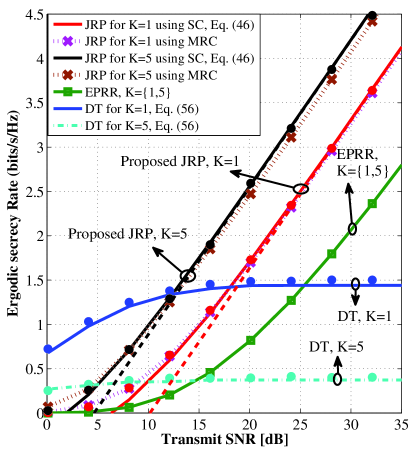
Figure 2 shows the achievable ESR versus the transmit SNR for NCE case. Our observations are summarized as follows:
-
1.
The ESR performance of the proposed JRP scheme is a monotonically increasing function of the transmit SNR while the ESR of the DT scheme converges to a constant value as presented in Section IV-B. The reason behind this behavior of the JRP scheme is that the injected jamming signal by the destination only degrades the received information signal at the malicious nodes and has no effect on the overall two-hop signal reception at the destination. As such, the secrecy performance of the DBCJ-based JRP scheme is superior to the performance of the DT policy in the high SNR regime, while the opposite behavior is observed at the low SNR regime. The reason is that by equipping the source with an LSMA and adopting an MRT beamformer the received SNR at the destination for DT becomes considerable, while the information leakage is negligible as computed in (12). We also mention that, as discussed in Section IV-A, the secrecy performance of the JRP is not satisfactory when the average transmit SNR of the second hop is low. Therefore, the proposed JRP suffers from w secrecy performance loss in the low SNR regime.
-
2.
The ESR performance of the JRP scheme increases as grows, which can be concluded form (22). This is because by increasing , the probability of emerging a stronger channel between the relays and destination grows and accordingly, the secrecy rate increases. Contrary to the JRP scheme, the ESR of the DT policy decreases by increasing . The reason is that according to (12), the received SNR at the destination is deterministic, while based on (13), the amount of information leakage increases as grows.
-
3.
The secrecy rate advantage of JRP scheme compared with EPRR is obvious. For example, the SNR gap between the proposed JRP scheme and EPRR is about 8 dB for case; this gap is about 13 dB for case to achieve the target transmission rate of 2 .
-
4.
The secrecy performance of the proposed JRP scheme with SC at the malicious nodes is close to the secrecy performance of the exact JRP with MRC technique.
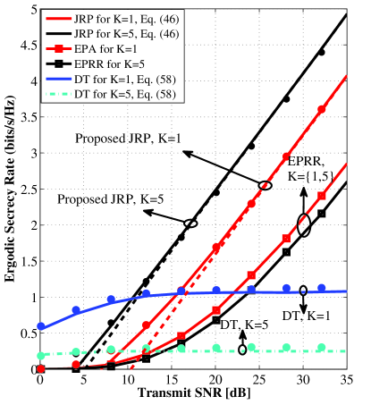
In Fig. 3, we plot the ESR performance versus the transmit SNR for the CE case. As can be seen, the proposed JRP scheme which is based on the near-optimal relay selection criterion in (23) is in perfect agreement with the exact numerical results across the entire SNR range of interest. As can be seen from Fig. 3, the ESR performance of the proposed JRP scheme increases by increasing , while the opposite is observed for DT policy. Furthermore, we can conclude from Fig. 3 that the ESR of the proposed scheme significantly outperforms the EPRR policy.
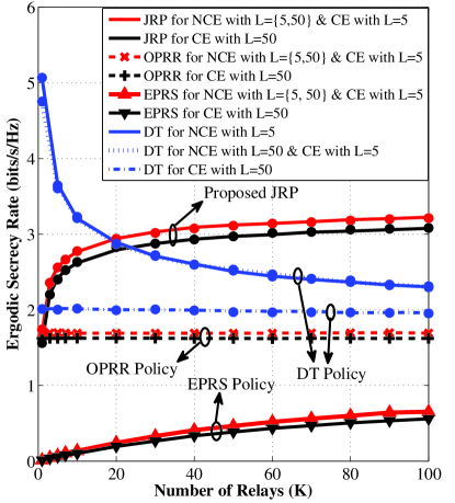
Figure 4 examines the impact of the number of untrusted relays on the ESR performance of the proposed JRP scheme for the NCE and CE cases. We set the number of source antennas to and the transmit SNR dB. We also consider two cases of small and large number of passive Eves. The following observations can be made from Fig. 4:
-
1.
As predicted by the analytical expressions and discussions in Section IV-B, the ESR performance of the proposed JRP scheme for NCE and CE cases is a monotonically increasing function of the number of untrusted relays . This new result highlights that, unlike the results in [21], [22], the proposed LSMA-based scheme increases the secrecy rate of the network by utilizing more untrusted relays.
-
2.
The proposed JRP scheme for the NCE case with any number of Eves offers a superior ESR performance relative to the CE case with large number of Eves . This event can be justified simply based on the new results presented in Section III-B. The reason is that by equipping the source with an LSMA, the amount of information leaked to the malicious nodes in the first of transmission is negligible compared to that one in the second phase. Therefore, for CE with small number of Eves , the ESR performance is the same as NCE case, while with large number of Eves, some information can be extracted by Eves, leading to ESR loss relative to NCE case.
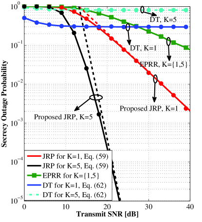
Figure 5: Overall SOP versus the transmit SNR for the NCE case with relays and passive Eves. The number of source antennas is set to and the target rate to . The asymptotic curves are shown with dashed lines using Eq. (61), while the filled circles depict the Monte-Carlo simulations. -
3.
When OPRR is adopted in the network, the ESR performance for both NCE and CE cases is a constant function of . The reason is that when one relay is randomly selected out of available relay nodes and OPA is applied, it is statically equivalent to the single-relay scenario with OPA. For large number of Eves , due to the collaboration between Eves, the ESR of CE case is somewhat fewer than the NCE case.
-
4.
The ESR performance of DT policy for NCE is a decreasing function of . The reason is that by increasing , the probability of emerging a stronger wiretap channel increases and therefore, the ESR decreases. However, for CE with large number of Eves, the ESR is a constant function with respect to . The reason is that both the amount of information leakage and the received SNR at the destination are independent of the number of untrusted relays. We note that according to (13) and the law of large numbers, we have which is independent of .
-
5.
The ESR performance of EPRS for both NCE and CE cases is an increasing function of . This result highlights the effectiveness of relay selection in LSMA-based security networks even without applying OPA.
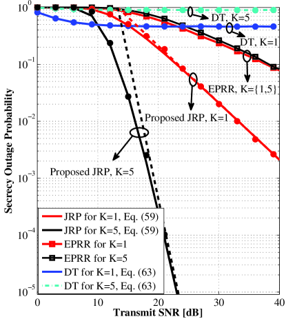
In Figs. 5 and 6, we compare the overall SOP versus the transmit SNR for NCE and CE cases, respectively. The results in Figs. 5 and 6 indicate that the SOP performance advantage of our proposed secure transmission scheme compared to the EPRR policy. As can be readily observed from these figures, unlike DT policy that the SOP performance converges to a nonzero constant as , the SOP of the proposed JRP scheme for both NCE and CE cases approaches zero in the asymptotic SNR regime. Furthermore, as mentioned in Section IV-C, the proposed JRP scheme achieves the diversity order equal to the number of untrusted relays, which can be obtained simply from the asymptotic curves in Figs. 5 and 6. Finally, we observe from Fig. 6 that, while the DT policy fails to establish confidential communication for target secrecy rate of , the proposed JRP scheme enhances the PLS remarkably. This highlights the efficiency of the proposed JRP scheme.
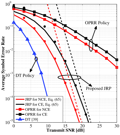
To study the level of reliability of the proposed secure transmission scheme, we plot the average SER metric in Fig. 7. We consider the multi-relay scenario with and QPSK modulation. For this network topology, the DT policy offers a superior average SER relative to the proposed JRP scheme. The reason is that the DT policy provisions a better SNR at the destination compared with the proposed scheme. Furthermore, as observed, the average SER of NCE case is lower than the CE case. The reason is that according to the received SINR at the destination in (37), we have . Moreover, we can conclude from Fig. 7 that the proposed JRP scheme is better compared to OPRR. For example, the SNR gap between the optimized network and OPRR is approximately 13 dB for NCE and 12 dB for CE, respectively, when . This is because the proposed JRP selects the relay with the largest second hop channel to signal transmission. Consequently, the achievable reliability of the proposed scheme is higher than the random relay selection of the OPRR policy. Evidently, unlike the OPRR, the proposed scheme attains diversity order .
VII Conclusion
In this paper, we addressed secure transmission in a two-hop relaying network including a multiple antennas source, a single antenna destination, single antenna untrusted relays and single antenna passive Eves. We considered two practical scenarios of NCE and CE. A novel JRP scheme has been proposed for security enhancement of the two NCE and CE networks. For the proposed JRP scheme, a new closed-form expression was presented for the ESR and the SOP as security metrics, and a new closed-form expression was derived for the average SER as a reliability measure over Rayleigh fading channels. We further evaluated the high signal-to-noise ratio slope and power offset of the ESR to reveal the impacts of system parameters on the achievable ESR. Our findings highlighted that the diversity order of the proposed JRP scheme is equal to the number of untrusted relays. Numerical results presented that the ESR of the proposed JRP scheme for NCE and CE cases increases as the number of untrustworthy relays grows.
It would be interesting to extend the results in this paper to the case, where trusted relays are also exist in the network. Thus, we would like to consider this case as future work.
Acknowledgments
The authors deeply thank Prof. Dimitris Toumpakaris and Prof. Lajos Hanzo for their constructive comments to improve the paper. The authors also would like to thank the editor and the anonymous reviewers for the constructive comments.
References
- [1] F. Rusek, D. Persson, B. K. Lau, E. G. Larsson, T. L. Marzetta, O. Edfors, and F. Tufvesson, “Scaling up MIMO: Opportunities and challenges with very large arrays,” IEEE Sig. Proc. Mag., vol. 30, no. 1, pp. 40-46, Jan. 2013.
- [2] E. G. Larsson, F. Tufvesson, O. Edfors, and T. L. Marzetta, “Massive MIMO for next generation wireless systems,” IEEE Commun. Mag., vol. 52, no. 2, pp. 186-195 , Feb. 2014.
- [3] D. Kapetanovic, G. Zheng, and F. Rusek, “Physical layer security for massive MIMO: An overview on passive eavesdropping and active attacks,” IEEE Commun. Mag., vol. 53, no. 6, pp. 21-27, Jun. 2015.
- [4] Y. Wu, R. Schober, D. W. K. Ng, C. Xiao, and G. Caire, “Secure massive MIMO transmission with an active eavesdropper,” IEEE Trans. Inf. Theory., vol. 62, no. 7, pp. 3880-3900, July 2016.
- [5] D. B. Rawat, T. White, M. S. Parwez, C. Bajracharya, and M. Song, “Evaluating secrecy outage of physical layer security in large-scale MIMO wireless communications for cyber-physical systems,” IEEE Internet of Things Journal, Apr. 2017.
- [6] X. He and A. Yener, “Two-hop secure communication using an untrusted relay: A case for cooperative jamming,” in Proc. IEEE Global Commun. Conf. (Globecom), New Orleans, LA, Dec. 2008, pp. 15.
- [7] A. Mukherjee, S. A. A. Fakoorian, J. Huang, and A. L. Swindlehurst, “Principles of physical layer security in multiuser wireless networks: A survey,” IEEE Commun. Surveys Tuts., vol. 16, no. 3, pp. 1550-1573, Feb. 2014.
- [8] X. Chen, D. W. K. Ng, W. Gerstacker, and H-H. Chen, “A survey on multiple-antenna techniques for physical layer security,” IEEE Commun. Surveys Tuts., vol. 19, no. 2, pp. 1027-1053, Jun. 2017.
- [9] Y. Zou, X. Wang, W. Shen, and L. Hanzo, “Security versus reliability analysis of opportunistic relaying,” IEEE Trans. Veh. Tech., vol. 63, no. 6, pp. 2653-2661, Jul. 2014.
- [10] C. Wang, H.-M. Wang, and X.-G. Xia, “Hybrid opportunistic relaying and jamming with power allocation for secure cooperative networks,” IEEE Trans. Wireless Commun., vol. 14, no. 2, pp. 589-605, Feb. 2015.
- [11] H.-M. Wang, C. Wang, and D. W. K. Ng, “Artificial noise assisted secure transmission under training and feedback”, IEEE Trans. on Signal Process., vol. 63, no. 23, pp. 6285-6298, Dec. 2015.
- [12] D. Fang, N. Yang, M. Elkashlan, P. L. Yeoh, and J. Yuan, “Cooperative jamming protocols in two-hop amplify-and-forward wiretap channels,” in Proc. IEEE Int. Conf. Commun. (ICC), Budapest, Hungary, pp. 2188-2192, Nov. 2013.
- [13] I. Krikidis, J. S. Thompson, and S. McLaughlin, “Relay selection for secure cooperative networks with jamming,” IEEE Trans. Wireless Commun., vol. 8, no. 10, pp. 5003-5011, Oct. 2009.
- [14] L. Wang, Y. Cai, Y. Zou, W. Yang and L. Hanzo, “Joint relay and jammer selection improves the physical layer security in the face of CSI feedback delays,” IEEE Trans. Veh. Technol., vol. 65, no. 8, pp. 6259-6274, Aug. 2016.
- [15] Z. Han, N. Marina, M. Debbah, and A. Hjorungnes, “Physical layer security game: Interaction between source, eavesdropper and friendly jammer,” EURASIP J. Wireless Commun. Netw., vol. 2009, pp. 452907-1 452907-10, Mar. 2009.
- [16] Y. Liu, J. Li and A. P. Petropulu, “Destination assisted cooperative jamming for wireless physical-layer security,” IEEE Trans. Inf. Foren. Sec., vol. 8, no. 4, pp. 682-694, Apr. 2013.
- [17] T. T. Kim and H. V. Poor, “On the secure degrees of freedom of relaying with half-duplex feedback,” IEEE Trans. Inf. Theory., vol. 57, no. 1, pp. 291-302, Jan. 2011.
- [18] S. I. Kim, I. M. Kim and J. Heo, “Secure transmission for multiuser relay networks,” IEEE Trans. Wireless Commun., vol. 14, no. 7, pp. 3724-3737, July 2015.
- [19] L. Wang, M. Elkashlan, J. Huang, N. H. Tran, and T. Q. Duong, “Secure transmission with optimal power allocation in untrusted relay networks,” IEEE Wireless Commun. Lett., vol. 3, no. 3, pp. 289-292, Jun. 2014.
- [20] A. Kuhestani and A. Mohammadi, “Destination-based cooperative jamming in untrusted amplify-and-forward relay networks: Resource allocation and performance study,” IET Commun., vol. 10, no. 1, pp. 17-23, Feb. 2016.
- [21] L. Sun, T. Zhang, Y. Li, and H. Niu, “Performance study of two-hop amplify-and-forward systems with untrustworthy relay nodes,” IEEE Trans. Veh. Technol., vol. 61, no. 8, pp. 3801-3807, Oct. 2012.
- [22] J.-B. Kim, J. Lim, and J. Cioffi, “Capacity scaling and diversity order for secure cooperative relaying with untrustworthy relays,” IEEE Trans. Wireless Commun., vol. 14, no. 7, pp. 3866-3876, July 2015.
- [23] L. Sun, P. Ren, Q. Du, Y. Wang, and Z. Gao, “Security-aware relaying scheme for cooperative networks with untrusted relay nodes,” IEEE Commun. Lett., vol. 19, no. 3, pp. 463-466, Sep. 2014.
- [24] W. Wang, K. C. Teh, and K. H. Li, “Relay selection for secure successive AF relaying networks with untrusted nodes,”IEEE Trans. Inf. Forensics Security., vol. 11, no. 11, pp. 2466-2476, Nov. 2016.
- [25] A. Mukherjee, “Physical-layer security in the Internet of Things: Sensing and communication confidentiality under resource constraints,” Proc. IEEE, vol. 103, no. 10, pp. 1747-1761, Oct. 2015.
- [26] J. Chen, H. Chen, H. Zhang and F. Zhao, “Spectral-energy efficiency tradeoff in relay-aided massive MIMO cellular networks with pilot contamination.,” IEEE Access, vol. 4, no. , pp. 5234-5242, Sept. 2016.
- [27] Z. Zhang, Z. Chen, M. Shen, and B. Xia,“Spectral and energy efficiency of multipair two-way full-duplex relay systems with massive MIMO” IEEE J. Sel. Areas in Commun., vol. 34, no. 4, pp. 848-863, Apr. 2016.
- [28] X. Zhou, R. K. Ganti and J. G. Andrews, “Secure wireless network connectivity with multi-antenna transmission,” IEEE Wireless Commun. Lett., vol. 10, no. 2, pp. 425-430, Feb. 2011.
- [29] P. L. Yeoh, N. Yang, and K. J. Kim, “Secrecy outage probability of selective relaying wiretap channels with collaborative eavesdropping,”in Proc. IEEE Global Commun. Conf. (Globecom), Dec. 2015, pp. 1-6.
- [30] L. Wang, M. Elkashlan, J. Huang, R. Schober, and R. K. Mallik, “Secure transmission with antenna selection in MIMO Nakagami-m fading channels,” IEEE Trans. Wireless Commun., vol. 13, no. 11, pp. 6054-6067, Nov. 2014.
- [31] I. S. Gradshteyn and I. M. Ryzhik, Table of Integrals, Series, and Products, 7th ed. New York: Academic, 2007.
- [32] P. Hao, X. Wang, and A. Behnad, “Relay authentication by exploiting I/Q imbalance in amplify-and-forward system,”in Proc. IEEE Global Commun. Conf. (Globecom), Dec. 2014, pp. 613-18.
- [33] X. Wang, P. Hao and L. Hanzo, “Physical-layer authentication for wireless security enhancement: Current challenges and future developments,” IEEE Commun. Mag., vol. 54, no. 6, pp. 152-158, June 2016.
- [34] A. Papoulis, Probability, Random Variables, and Stochastic Processes. New York: McGraw-Hill, 1984.
- [35] Z. Wang and G. B. Giannakis, “Outage mutual information of space-time MIMO channels,” IEEE Trans. Inf. Theory, vol. 50, no. 4, pp. 657-662, Apr. 2004.
- [36] A. Bletsas, A. Khisti, D. P. Reed, and A. Lippman, “A simple cooperative diversity method based on network path selection”, IEEE J. Sel. Areas Commun., vol. 24, no. 3 pp. 659-672, Mar. 2006.
- [37] S.M. Kay, Fundamentals of Statistical Signal Processing, Volume I: Estimation Theory, Prentice Hall, 1998.
- [38] A. M. Tulino and S. Verdu, “Random matrix theory and wireless communications,” Foundations and Trends in Communications and Information Theory, vol. 1, no. 1, pp. 1-182, Jun. 2004.
- [39] J. G. Proakis, Digital Communications. 5th ed. McGraw-Hill, New York, 2008.
- [40] Z. Rezki and M. S. Alouini, “Secure diversity-multiplexing tradeoff of zero-forcing transmit scheme at finite-SNR,” IEEE Trans. Commun., vol. 60, no. 4, pp. 1138-1147, Apr. 2012.