Topological cascade laser for frequency comb generation in -symmetric structures
Abstract
The cascade of resonant topological structures with -symmetry breaking is shown to emit laser light with a frequency-comb spectrum. We consider optically active topological Aubry-André-Harper lattices supporting edge-modes at regularly spaced frequencies. When the amplified resonances in the -broken regime match the edge modes of the topological gratings, we predict the emission of discrete laser lines. A proper design enables to engineer the spectral features for specific applications. The robustness of the topological protection makes the system very well suited for a novel generation of compact frequency comb emitters for spectroscopy, metrology, and quantum information.
pacs:
42.65.Sf,42.50.Md,03.65.Vf,78.67.PtApplications of frequency combs (FC) Udem are widespread and range from classical and quantum metrology to ultrafast spectroscopy. Diddams FC are coherent light sources with equally spaced spectral lines and are realized by highly nonlinear optical fibers, mode-locked lasers, and microring resonators. Jones ; Herr12 ; Herr14 ; Kippenberg Compact and robust FC laser sources in different spectral ranges are subject to intense research and may potentially revolutionize photonics and quantum optics, including quantum cascade lasers and related terahertz and mid-infrared applications, as pollution detection and security. burghoff_terahertz_2014 ; rosch_octave-spanning_2015 ; hugi_mid-infrared_2012 ; combrie2016 The key challenge for integrated FC sources is finding ideas to overcome limitations due to perturbation effects, as material disorder and dispersion. From a fundamental point of view, classical and quantum properties of FC in complex structures are only marginally understood.Reimer1176
Many authors Haldane ; Raghu ; Rechtsman ; Khanikaev recently applied topological concepts in optics, and “topological photonics” is a rich and growing field. Hasan ; Lu However, despite the potential robustness with respect to disorder due to topological protection, FC laser emitters have not yet been considered because (i) resonant light-emitting topological systems have been only marginally studied, and (ii) edge-state laser sources, commonly studied in topological lasers, are intrinsically narrow-band, and one can argue about topological systems for broad-band operation.
In this Letter, we study cascaded topological resonances undergoing a -symmetry breaking transition Bender2 ; Makris and demonstrate that it is possible to design a topologically protected FC active emitter. When the amplified resonances in the -broken regime match the edge modes dispersion of the underlying topological lattice, we predict the emission of regularly spaced resonances. A designed -symmetric topological-cascade emits frequency combs in target spectral ranges suitable, e.g., for dual-comb spectroscopy and related applications.
Proposals to use topological effects in the design of novel photonic lattices supporting many frequency channels for FC generation, with topological protection against disorder, have been recently performed in microring resonators Ozawa ; Yuan . Topology allows to tune the competition with bulk extended modes and obtain single mode lasing on edge states of targeted wavelength. In fact the modulation of the structure produces gapless states whose localization at the edges induces a difference between the threshold gain of the targeted mode and its adjacent modes, giving excellent modal discrimination. Moreover by shaping the gain, parity-time symmetry further reduces the lasing threshold.
We here consider one-dimensional (1D) lattices Lang ; Ganeshan ; Kraus ; Posha ; PoshaAr ; PiCo1 with the Aubry-Andr-Harper (AAH) modulation Aubry ; Harper ; Thou ; Hofs ; Guo1 ; Su . We study resonant photonic structures Posha that have laser-light emitting topological edge states PiCo1 , which are symmetry protected with respect to structural perturbations at variance with surface statesDyakonov ; kavokin ; Shockley .
In our photonic AAH model, active layers are centered at positions embedded in an homogeneous bulk material . is the Harper modulation Harper , is the primary lattice period and is
the modulation strength. For with and integers, the lattice displays two commensurate periods with resonant layers in the unit-cell.
These resonant structures Posha ; PiCo1 are analogues of complex staggered potentials for electrons Su ; a proper gain and loss distribution Schomerus ; Makris ; Guo ; Ruter ; Longhi1 realizes synthetic optical media with parity-time () symmetryZheng ; Bender ; Bender2 . This suggests
adopting active components for lasers based on protected modes due to topological orderFeng ; Hodaei .
Letting the propagation direction, -symmetry implies a constraintMakris on the complex dielectric function .
This constraint is satisfied El ; Makris2 by alternating an even number of layers with with and . More complicated index distributions allow the balance between gain and loss around a symmetry point Sean and have a -symmetric configuration with a rich phase diagram.
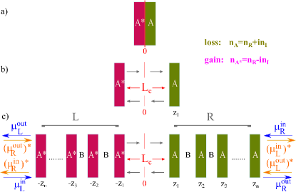
We consider the structure shown in Figure 1 realized by joining a right region (R) with dielectric function
| (1) |
with a left (L) region where:
| (2) |
In Eqs.(1,2), is the Heaviside step function, , for , and so that, if the site in has a gain/loss coefficient , the site in has a loss/gain , thus realizing a -symmetric structure. A central layer with length and real dielectric function connects L and R regions. indicates the number of active A layers in L and R sections; and , hereafter. The shifted coordinates are with .
We study the transition to broken symmetry by the eigenvectors and eigenvalues of the scattering matrix Chong . maps incoming to outgoing coefficients by . Blue and orange arrows in Fig. 1 show the scattering configuration before (green) and after (orange) a transformation. In the -symmetric configuration and . For the eigenvectors such that , one has . Letting and we have
where () is the left (right) reflection amplitude and the transmission coefficient independent of the direction of incidence. Introducing the components of the transfer matrix, one has , , so that symmetry implies
| (3) |
with the equal sign corresponding to the symmetry breaking threshold.
We analyze the structure in Fig. 1c exploiting the properties of the transfer and scattering matrices Zyablovsky : and , and the symmetry relations between R and L sections. These allow to easily obtain transfer and scattering matrices of the whole -symmetric structure from the knowledge of just the transfer matrix on the single period of the R section.
First we remark that, letting the phase shift , the structure is spatially inverted under the reversal Posha so that the transfer matrix for the left-hand side is obtained by the corresponding right-hand side matrix by .
The transfer matrix of the complete system is then , where is the diagonal transfer matrix of the central layer with entries and the Kronecker delta.
Moreover the scattering matrix can be obtained by by simple components exchangeMostafazadeh .
The left scattering matrix is then given by
since:
- time-reversal swaps incoming and outgoing states so that ;
- parity exchanges the left and right sides and gives where is the Pauli matrix.
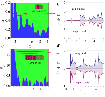
To gain insight into the physics of our -symmetric topological structure, we first consider the simplest systems in Fig. 1. The two-layer structure in Fig.1a is made by a pair of loss (+) and gain (-) media with length and refractive index ; the structure in Fig.1b includes also a central layer. Figure 2a,b show the corresponding phase diagrams . The dashed line in Figure 2a [equal sign in Eq. (3)] gives the symmetry breaking curve in the absence of the central layer: the structure undergoes a phase transition when increases for a fixed gain/loss. For the three-layer structure in Figure 2b, the phase diagram shows several broken-symmetry regions above a threshold value . Figure 2c,d show the eigenvalues of the scattering matrix. In the symmetric phase, one has two unimodular eigenvalues (). In the broken-symmetry regime, one finds two eigenvalues with reciprocal moduli (). For the two-layer structure, Fig.2c shows that above a critical frequency, one eigenvalue (blue curve) exhibits amplification. For the three-layer structure (Figure 2d) different regions with amplified modes are present.

Moreover, the eigenvalues define the threshold for lasing as a real frequency pole such that . Due to -symmetry , we have , i.e., the system also shows a real frequency zero. This implies that, at the laser threshold, a pole () and a zero () of the scattering matrix coincide Longhi and the system is also a coherent perfect absorber Chong2 .
When increasing the number of real-index layers, internal resonances and oscillations in the non-hermiticity parameters produce a more complex phase diagram Chong . Letting , Fig. 3a shows for active layers in and Fig. 3b the eigenvalues for . Fig. 3c shows the case and Fig. 3d the corresponding eigenvalues for . Several amplified modes exist with a rich spectral distribution. ().
To investigate the possibility of FC emission, we analyze the topological features of the complete structure in Fig. 1c. The two left (L) and right (R) sections exhibit localized left () and right (r) modes with frequencies due to symmetry. This can be verified by the left-edge state frequencies , which are the poles of the left reflection coefficient Posha . When , for with and integers, the spectral gaps of the un-modulated structure () at split into gaps Hofs .
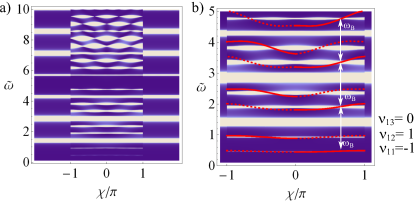
Figure 4a shows the absolute value of reflectivity for and reveals the allowed (dark) and forbidden (bright) bands for , and . Each stop band, labeled by indexes with and , is characterized by the topological invariant winding number
| (4) |
the extra phase in units of of the reflection coefficient when varies in the range () with in the stop band PoshaAr . For we have , . Due to bulk-boundary correspondence Graf , we have edge modes in the corresponding gaps. Figure 4b shows the dispersion of these edge-states localized at the left and right edges. For a given , the edge-states frequencies are equally spaced , as shown in details in Fig. 5a. These edge modes are amplified as they lay in the broken -symmetry range (see the curve in Fig. 5b). This result is typical of the analyzed structures with the Harper modulation for any , which can be varied to optimize the spectral emission.
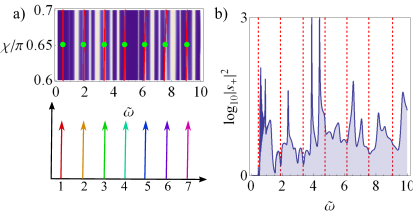
Our analysis shows that the considered system support a set of equally spaced topologically protected edge states that are amplified in the broken symmetry regime. A key result is that one can design the structure on the frequency range of interest. For a single structure with a given value , the mode spacing, is much wider then the typical mode-spacing adopted in FC. However, one can realize any kind of FC by cascading the single structure. By various -topological structures with different values of the period , one can obtain fractions of for the mode spacing. Figure 6 shows an example: a comb spectrum in the visible range . The design starts with a structure with parameters and such that the lowest matches the eV value. This kind of structures can be realized by standard molecular beam epitaxy techniques as, e.g., for VCSEL laser employing AlGaAs as MQW for gain (as in ref. arx ). generates the fundamental comb shown as gray arrows in Fig. 6 with line spacing eV. A further cascaded structure with adds the green lines and reduces the spacing in the range to .
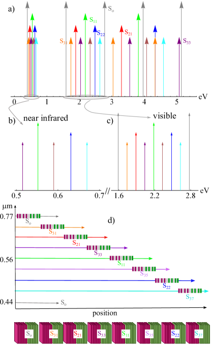
This procedure can be iterated and each cascaded structure adds topologically protected lines to the emitted spectral comb. Indeed, recursively halving each range between two consecutive lines, equispaced modes in the range with spacing can be obtained. This results in cascading -topological structures to the initial . For each structure , we have for and odd . Figure 6a shows the spectral features of the emission of seven cascaded -symmetric topological systems. The overall structure sustains the emission of a FC in the visible range (Fig. 6c) with line spacing 0.15 eV and, in addition, a FC in the near infrared range (Fig. 6b) with line spacing 40 meV.
In conclusion, the interplay of gain and loss in a -symmetric topological structure allows the amplification of multiple equally spaced frequencies when the resonances of lasing modes crosses the dispersion of edge-modes. A suitable design of the gain distribution of the topologically-protected edge-modes and the cascade of multiple lattices are the ingredients for realizing frequency-comb emitters with a prescribed spectral content. The inherent robustness of topological structures with respect to fabrication tolerances and the many degrees of freedom for design and optimization, including, e.g., spatial shaping of the gain profile, show the possibility of engineering specific applications, as dual-combs emitters or integrated optical clocks for metrology. Not only -symmetry breaking in active topological systems reveals novel complex forms of light-matter interaction, but one can envisage a new generation of compact frequency-comb lasers and optically integrated sources of non-classical quantum states.
We acknowledge support from the Templeton foundation (grant number 58277) and from the project PRIN NEMO (reference 2015KEZNYM).
References
- (1) T. Udem, R. Holzwarth, T. W. Hansch, Nature 416, 233 (2002)
- (2) S. A. Diddams et al, Science 293, 825 (2001)
- (3) D.J. Jones et al, Science 288, 635 (2000)
- (4) T. Herr, K. Hartinger, J. Riemensbergeret al, Nature Photon. 6, 480, (2012)
- (5) T. Herr et al., Nature Photon. 8, 145, (2014)
- (6) T. J. Kippenberg, et al. Science 332, 555 (2011)
- (7) D. Burghoff, et al, Nature Photonics 8, 462 (2014)
- (8) M. Rasch, et al, Nature Photonics 9, 42 (2015)
- (9) A. Hugi, et al, Nature 492, 229 (2012)
- (10) S. Combrié, G. Lehoucq, G. Moille, A. Martin, A. De Rossi, arXiv:1704.04267 (2016)
- (11) C. Reimer, et al, Science 351, 1176 (2016)
- (12) F.D.M. Haldane, and S.Raghu, Phys. Rev. Lett. 100, 013904 (2008).
- (13) S. Raghu, F.D.M. Haldane, Phys. Rev. A 78, 033834 (2008).
- (14) M.C. Rechtsman, J.M. Zeuner, Y. Plotnik, Y. Lumer, D. Podolsky, F. Dreisow, S. Nolte, M. Segev, A. Szameit Nature 496, 196 (2013)
- (15) A. B. Khanikaev, S. Hossein-Mousavi, W.-K. Tse, M. Kargarian, A. H. MacDonald, and G. Shvets, Nature Mater. 12, 233 (2013)
- (16) M. Z. Hasan and C. L. Kane Rev. Mod. Phys. 82, 3045 (2010)
- (17) L. Lu, J.D. Joannopoulos, and M. Soljai, Nature Photonics, 8, 821, (2014).
- (18) K. G. Makris, R. El-Ganainy, D. N. Christodoulides, and Z. H. Musslimani, Phys. Rev. Lett. 100, 103904 (2008)
- (19) C. M. Bender, S. Boettcher, Phys. Rev. Lett. 80, 5243 (1998)
- (20) T. Ozawa, H. M. Price, N. Goldamn, O. Zilberberg, I. Carusotto Phys. Rev. B 93, 043827 (2016)
- (21) L. Yuan, Y. Shi, S. Fan Optics Lett. 41, 741 (2016)
- (22) L.-J. Lang, X. Cai, and S. Chen, Phys. Rev. Lett. 108, 220401 (2012).
- (23) S. Ganeshan, K. Sun, and S. Das Sarma, Phys. Rev. Lett. 110, 180403 (2013).
- (24) A. V. Poshakinskiy, al., Phys. Rev. Lett. 112, 107403 (2014).
- (25) A. V. Poshakinskiy, A. N. Poddubny, M. Hafezi Phys. Rev. A 91, 043830, (2015)
- (26) L. Pilozzi, C. Conti Phys. Rev. B 93, 195317 (2016)
- (27) Y.E. Kraus, O. Zilberberg, Phys. Rev. Lett. 109, 116404 (2012)
- (28) S. Aubry, G. Andr, Ann. Israel. Phys. Soc. 3, 133 (1980)
- (29) P. G. Harper, Proc. Phys. Soc., London, Sect. A 68, 874 (1955)
- (30) D. J. Thouless, M. Kohmoto, M. P. Nightingale, and M. den Nijs, Phys. Rev. Lett. 49, 405 (1982)
- (31) D. R. Hofstadter, Phys. Rev. B 14, 2239 (1976)
- (32) H. Guo Phys. Lett. A 378, 1316 (2014)
- (33) W. Su, J. R. Schrieffer, and A. J. Heeger, Phys. Rev. Lett. 42, 1698 (1979).
- (34) M.I. Dyakonov, Soviet Physics JETP 67, 714 (1988)
- (35) A. V. Kavokin, I. A. Shelykh, G. Malpuech, Phys. Rev. B 72, 233102 (2005)
- (36) W. Shockley, Phys. Rev. 56, 317 (1939)
- (37) A. J. Heeger, S. Kivelson, J. R. Schrieffer, and W. P. Su, Rev. Mod. Phys. 60, 781 (1988)
- (38) H. Schomerus, Opt. Lett. 38, 1912 (2013)
- (39) A. Guo, G. J. Salamo, D. Duchesne, R. Morandotti, M.Volatier-Ravat, V. Aimez, G. A. Siviloglou, and D. N.Christodoulides, Phys. Rev. Lett. 103, 093902 (2009)
- (40) C. E. Ruter, K. G. Makris, R. El-Ganainy, D. N. Christodoulides, M. Segev, and D. Kip, Nature Phys. 6, 192 (2010)
- (41) S. Longhi, J. Phys. A Math. Theor. 47, 165302 (2014)
- (42) M. C. Zheng, D. N. Christodoulides, R. Fleischmann, and T. Kottos, Phys. Rev. A 82, 010103(R) (2010)
- (43) C. M. Bender, Rep. Prog. Phys. 70, 947 (2007)
- (44) L. Feng, Z. J. Wong, R. Ma, Y. Wang, and X. Zhang, Science 346, 972 (2014)
- (45) H. Hodaei, M.-A. Miri, M. Heinrich, D. N. Christodoulides, and M. Khajavikhan, Science 346, 975 (2014)
- (46) R. El-Ganainy, K. G. Makris, D. N. Christodoulides, Z.H. Musslimani, Opt. Lett. 32, 2632 (2007).
- (47) K.G. Makris, R. El-Ganainy, D.N. Christodoulides, Phys. Rev. A 81, 063807 (2010).
- (48) S. Nixon, J. Yang Phys. Rev. A 93, 031802(R), (2016)
- (49) Y. D. Chong, L. Ge, A.D. Stone, Phys. Rev. Lett. 106, 093902 (2011)
- (50) A. A. Zyablovsky, A. P. Vinogradov, A. A. Pukhov, A. V. Dorofeenko, and A. A. Lisyansky, Physics Uspekhi, 57, 1063 (2014)
- (51) A. Mostafazadeh, Phys. Rev. Lett. 102, 220402 (2009)
- (52) S. Longhi, Phys. Rev. A 82, 031801(R) (2010)
- (53) Y. D. Chong, L. Ge, H. Cao and A. D. Stone, Phys. Rev. Lett. 105, 053901 (2010)
- (54) G.M. Graf, M. Porta, Commun. Math. Phys. 324, 851 (2013)
- (55) Kou-Bin Hong, Chun-Yan Lin, Tsu-Chi Chang et al. arXiv:1704.08026