High vacuum compatible fiber feedthrough for hot alkali vapor cells
Abstract
We demonstrate a method to produce vacuum tight, metal free, bakeable and alkali compatible feedthroughs for optical fibers. The manufacturing process mainly relies on encasing fibers made of fused silica with glass materials with lower melting points by heating. We analyze the vacuum and optical performance of the devices by various methods including helium leak checking and several spectroscopic schemes, among others electromagnetically induced transparency involving Rydberg states.
I Introduction
The spectroscopy of ultracold atomic gases, ions and molecules as well as atomic and molecular vapors at room temperature typically requires vacuum conditions ranging from . For an optimal matter light coupling, it is desirable to directly apply optical fibers close to the atomic sample which requires suitable vacuum feedthroughs. For stainless steel vacuum chambers with KF or CF systems such feedthroughs exist, based on PTFE and metallic ferrules in a swage-lock type configuration (Abraham and Cornell, 1998; Miller and Moshegov, 2001). They are used for example to setup fiber-pigtailed optical tweezers for single-atom trapping Garcia et al. (2013), or to insert tapered fibers into clouds of laser-cooled atoms Le Kien and Rauschenbeutel (2015). A more simple approach is to just seal the feedthrough with epoxy, e.g. used to install microscopic Fabry-Pérot cavities Colombe et al. (2007). The drawback of such feedthroughs is their limited vacuum compatibility, especially when exposed to highly reactive and corrosive alkali vapors, which results in chemical reactions and additional gas loads. The consequence is the need for permanent pumping to maintain the vacuum. Another point is a reduced thermal resistance, which only allows bake-out temperatures of up to . An alternative method is to couple the light through a chamber window into the fiber inside the vacuum Epple et al. (2014) for the price of reduced coupling efficiency and stability. For enclosed vacuum systems without a pump, as it is standard for spectroscopy cells made of glass, it is mandatory to have an absolute vacuum tight feedthrough made of materials with low outgassing rates. One alternative is to fill hollow core fibers under vacuum conditions with a gas and then to seal the ends vacuum tightly Benabid et al. (2005). For a more general applicability, it is desirable to have a versatile fiber feedthrough only made of glass materials to avoid out-gassing, chemical reactions and coupling losses while still having the ability to heat the system to high temperatures. In the following, we explain the production and test of such feedthroughs, and conclude with applications made possible by this technique.
II Manufacturing Process
The manufacturing process relies on the diverging softening points of different glass materials. Here we combine glass types with a rather low melting point (borosilicate, ) to vacuum tightly enclose an optical fiber with a much higher temperature stability (fused silica, ). The anticipation was that the almost melted borosilicate adheres onto the fused silica fiber and does not crack due to different expansion coefficients ( vs. ) when temperatures are changed, e.g. for a typical bake-out procedure.
Through a carefully performed manufacturing process as described below, we have been able to produce such a heterogeneous combination of materials, which also maintains the optical performance of the fibers. For the purpose of a proof of principle, we used standard optical single-mode fibers (SMF, Thorlabs 780HP) and multi-mode fibers (MMF, Thorlabs FG050LGA).
II.1 Production Steps
Before processing, we have mechanically stripped a SMF and a MMF on a length of about (Fig. 1(a)) and subsequently removed the residual coating by wiping with isopropyl alcohol soaked anti-static tissues to prevent dust contamination. As a jacket we chose a borosilicate tube with inner ( outer) diameter which is capable of surrounding most commercial fibers.
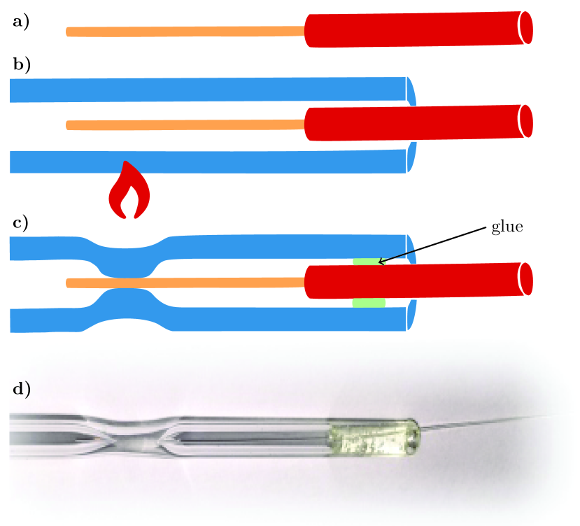
To allow an optimal heating from all sides, we installed the capillary inside a self-built lathe. The lathe consists of two rotatable drill chucks driven by synchronized stepper motors. The distance between the mounts can be adjusted to a maximum length of . To reduce avoidable heating of the fibers, we pre-shrink the inner diameter of the tube, before inserting the fiber. This is achieved by moderately heating the glass with a hand torch (e.g. Proxxon Microflam) until the inner diameter roughly matches the fiber cladding size. When heated carefully, the glass-tube slowly starts to collapse by itself due to the surface tension. Both utilizing a lathe and pre-shrinking is no mandatory step, but significantly facilitates the following process.
The fiber is then inserted into the tube. Alignment is carried out such that the protective polyimide coating has enough distance () to the sealing position, but still remains within the tube. The length of the stripped part of the fiber has to be adjusted accordingly beforehand.
The lathe is operated at around 3-5 rps while heating the borosilicate tube with the hand torch (Fig. 1(b)). To avoid twisting the fiber, either its length needs to be short enough, or the rest of the fiber is coiled up and fixed onto the rotating parts of the lathe. As the tube collapses onto the fiber, the torch can be moved along the axis to further increase the length of the seal. Due to the limited heat of the hand torch and the short exposure (around ), the melting point of the fused silica is not reached, preserving both functionality and shape of the fiber. However, the melting point of the borosilicate is exceeded. Due to surface tension, the tube collapses and forms a durable and vacuum tight seal around the fiber cladding (Fig. 2).
The connection between tube and fiber is distinctly brittle because of the lacking cladding. Especially slight twists are likely to break the device. To prevent such accidental rupture, a suitable glue is then applied to the coated part of the fiber inside the tube but outside of the intended vacuum part. (Fig. 1(c)). As the glue only provides mechanical stability, the choice here is not critical, as long as temperature compatibility is given. We used Epo-Tek 301. An exemplary photograph of such a feedthrough is shown in Fig. 1(d).
The finalized feedthrough can be attached to more elaborate devices, such as the flat polished window of a precision spectroscopy cell. Alternatively, the tube is integrated into a construction in advance and the sealing process is carried out subsequently.
II.2 Sample Preparation
To later perform spectroscopic analysis of the devices, the assembled feedthroughs were attached to a larger tube with a flattened region for free beam spectroscopy. The devices were evacuated to , each filled with a droplet of rubidium and sealed conventionally on the fiber-averted side. The vapor pressure has been adjusted by temperature.
III Performance Analysis
III.1 Vacuum Performance
For helium leak checks, the devices were attached to an all-glass KF16 flange and connected to a commercial leak detector (Leybold Phoenixl 300). The helium leak-rate was below the detection limit of , measured at both room temperature and . Apparently, the difference in thermal expansion of borosilicate and fused silica ( and , respectively) plays only a very minor role for the vacuum tightness: For the typical diameter of a stripped fiber of , a temperature change of would yield a theoretical difference of diameters of around . In a very simplified picture, a pipe of diameter and length has a through-put of Steckelmacher (1966)
| (1) |
with Boltzmann constant , temperature , molecular mass and pressure gradient . For helium and nitrogen (N2) at and a pressure difference of , the numerical values are and , respectively. Both values are already above the measured rate. The actual gap should have a much larger cross section than the aforementioned tube (area times larger). Presumably, this gap is much smaller or even nonexistent, for instance due to elasticity of the fiber.
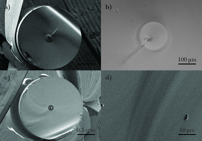
To further substantiate the smoothness of the interface between fiber and capillary, we examined the profile with scanning electron microscopy (Fig. 2). For room temperature, apparently the tube fuses onto the fiber surface without a gap.
III.2 Spectroscopic Pressure Observation
A convenient way to study the vacuum condition inside the vapor cell are narrow-band spectroscopy schemes, which are sensitive to collisions with a potential background gas. Such a perturbing gas can either result from a physical or a virtual leak, from a chemical reaction of rubidium with residual contaminants or from outgassing of the doped fiber.
The rubidium filled sample is heated and kept at temperatures above for 30 days. Different spectroscopy schemes with different sensitivities to a background gas are then applied repeatedly. Fig. 3 displays typical spectra captured for analysis.
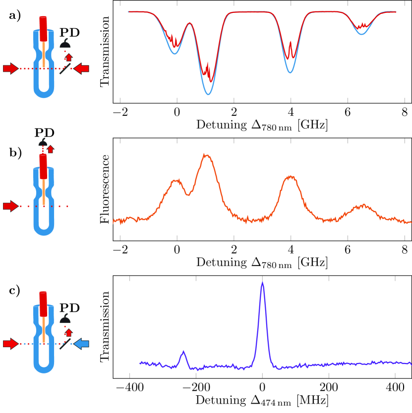
Being easy to set up and widely available, we first applied absorption and saturation spectroscopy. Fig. 3(a) shows resulting measurements of both absorption (blue curve) and saturation spectroscopy (red curve) of the SP3/2 transition. The Lamb-Dips are well resolved, and thus motivate further analysis. The fluorescence signal can be easily captured with the multi-mode fiber. Fig. 3(b) shows the outcoupled light, when exciting atoms in front of the cleaved fiber tip inside the cell.
A much more sensitive probe of the vacuum are highly excited Rydberg states, which are just by their mere size more likely to collide with atoms from a potential background gas. To provide a quantitative measure for the background pressure the probe line-width of the Electromagnetically Induced Transparency (EIT) ladder scheme is monitored (Fig. 3(c)). No significant increase in line-width is observed: the FWHM deviated less than from the initial measure of , and remained below at the end of the observation period. As EIT spectroscopy was possible during the whole period, the background pressure can be assumed to be stable. Assuming nitrogen as the disturber gas (i.e. leaked air), this would correspond to a final absolute pressure of , or a (constant) leak rate of over the whole period of 30 days Petitjean et al. (1984).
III.3 Optical Properties
The functionality of the fiber is maintained during the sealing process. Collecting fluorescence light originating from a free space propagating beam (c.f. Fig. 3(b)) works as well as monitoring the fluorescence originating from light coming out of the fiber. Fig. 4 shows the characteristic cone of fluorescing excited atoms around the fiber tip, emerging from the numerical aperture.
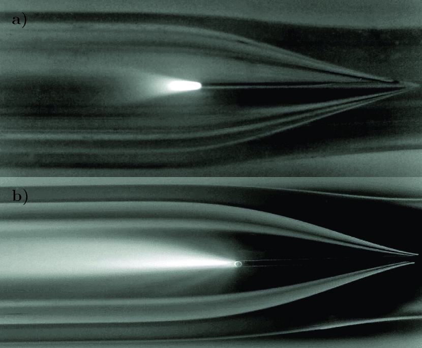
Transmission measurements with the fibers before and after the sealing process show no change in transmission performance. Also, there is no leakage light visible in Fig. 4. However, the mechanical and thermal stress the fiber is exposed to might lead to changes in polarization dependent properties.
IV Summary/Outlook
We described a fabrication method for fiber feedthroughs, which is both high vacuum and alkali vapor compatible. The performance of such devices was tested using helium leak checking, spectroscopic analysis and fluorescence monitoring.
It is now possible to attach the feedthrough to conventional Conflat vacuum flanges to facilitate a bakeable fiber access to generic vacuum chambers, or to directly interface it to pump free vapor cells. Especially sensing applications for electromagnetic fields greatly benefit from the technology, because the use of metal was completely avoided and only dielectric materials are involved. Spectroscopy of alkali atoms inside hollow core fibers Veit et al. (2016) in particular provide a promising starting point for such a sensor, and becomes feasible with the presented technique.
Funding. Baden-Württemberg Stiftung within the project Micro2Sens, BMBF within Q.Com-Q (Project No. 16KIS0129). Acknowledgment. Arzu Yilmaz acknowledges funding by the Deutsche Telekom Stiftung. Harald Kübler acknowledges personal support from the Carl-Zeiss foundation. The authors thank Frank Schreiber and Joachim Lefèvre for technical support, Mario Hentschel for the SEM pictures and the Max Planck Institute for the Science of Light for providing the HC-PCF.
References
- Abraham and Cornell (1998) E. R. Abraham and E. A. Cornell, Applied Optics 37, 1762 (1998).
- Miller and Moshegov (2001) D. Miller and N. Moshegov, Journal of Vacuum Science & Technology A 19, 386 (2001).
- Garcia et al. (2013) S. Garcia, D. Maxein, L. Hohmann, J. Reichel, and R. Long, Applied Physics Letters 103, 114103 (2013).
- Le Kien and Rauschenbeutel (2015) F. Le Kien and A. Rauschenbeutel, Physical Review A 91, 053847 (2015).
- Colombe et al. (2007) Y. Colombe, T. Steinmetz, G. Dubois, F. Linke, D. Hunger, and J. Reichel, Nature 450, 272 (2007).
- Epple et al. (2014) G. Epple, K. Kleinbach, T. Euser, N. Joly, T. Pfau, P. S. J. Russell, and R. Löw, Nature communications 5 (2014).
- Benabid et al. (2005) F. Benabid, F. Couny, J. Knight, T. Birks, and P. S. J. Russell, Nature 434, 488 (2005).
- Steckelmacher (1966) W. Steckelmacher, Vacuum 16, 561 (1966).
- Petitjean et al. (1984) L. Petitjean, F. Gounand, and P. Fournier, Physical Review A 30, 736 (1984).
- Veit et al. (2016) C. Veit, G. Epple, H. Kübler, T. G. Euser, P. S. J. Russell, and R. Löw, Journal of Physics B: Atomic, Molecular and Optical Physics 49, 134005 (2016).