Rate equations for a Na+ channel gating master equation during the action potential within a neural membrane
S. R. Vaccaro
Department of Physics, University of Adelaide, Adelaide, South Australia,
5005,
Australia
svaccaro@physics.adelaide.edu.au
The action potential in a neural membrane is generated by Na+ and K+ channel ionic currents that may be calculated from a current equation and the
rate equations for activation variables and , and the Na+ inactivation variable h. Assuming that a Na+ channel has three activation sensors,
and activation and inactivation are cooperative processes, a twelve state master equation that describes channel gating may be reduced to
kinetic equations for a five state system when the occupational probability of the first inactivated state is small, and the remaining inactivated states contribute to
a total inactivated state. In the case of independent activation sensors, the inactivation rate is, in general, dependent on the activation variable as well as
the forward inactivation transition rates. However, when has a faster time constant than , the inactivation rate may be approximated by a
voltage-dependent function, and therefore, the solution of the master equation during an action potential may be approximated by the solution of
Hodgkin-Huxley rate equations for and .
INTRODUCTION
By assuming that Na+ channel activation is independent of inactivation, the Hodgkin-Huxley (HH) rate equations for Na+ and K+ channels and the membrane current equation
provide a good account of the action potential waveform, the threshold potential and subthreshold oscillations [1], and the approach has been applied to a wide range of
voltage-dependent ion channels in nerve, muscle and cardiac membranes. The HH rate equations for the Na+ channel are exact solutions of an eight state master equation for
channel gating where the inactivation sensor and three activation sensors are independent [2, 3].
However, subsequent experimental studies have shown that the probability of Na+ inactivation increases with the degree of activation of the channel [4],
the recovery from inactivation is more probable following deactivation [5], and the kinetic equations for coupled Na+ activation and inactivation processes
represent ion channel states and their transitions, and provide a good description of the ionic and gating currents during a voltage clamp [6].
From the solution of a nine state master equation that describes Na+ channel gating with two independent activation sensors and a coupled inactivation process,
the open state probability during a depolarizing clamp may be expressed as where m(t) and h(t) satisfy rate equations, and therefore, the HH description of the
Na+ current during a voltage clamp is consistent with a coupled Na+ channel gating model [7].
In this paper, it is shown that during an action potential, the solution of a six state master equation that describes coupling between a single
Na+ channel activation sensor and a two-stage inactivation process may be approximated by interacting rate equations for activation and inactivation, when the first forward
and backward inactivation transitions are rate limiting. When the Na+ channel has three activation sensors, by application of a reduction method, a twelve state master equation may be
expressed as kinetic equations for a five state system, and if the activation sensors are independent, the inactivation rate is dependent on the activation variable
but may be approximated by a voltage-dependent function when has a faster time constant than . Therefore, the solution of the Na+ channel master equation during an
action potential may be approximated by the solution of HH rate equations for and .
Na+ CHANNEL MASTER EQUATION WITH A SINGLE ACTIVATION SENSOR
In this section, it is assumed that the activation of a single voltage sensor regulating the Na channel conductance is coupled to a two-stage inactivation process (see Fig. 1),
and therefore, the kinetics may be described by a six-state master equation, that may be reduced to a four state system when the first forward and backward transitions are
rate limiting [7] (see Fig. 2)
(1)
(2)
(3)
(4)
where , , , are the occupational probabilities for the closed, open and inactivated states.
The Na current during deactivation of an inactivated ion channel is small [4], and therefore, the recovery rate . It may be
assumed that because inactivation is a slower process than activation, and during the action potential, , and therefore,
from Eq. (3)
(5)
That is, Eqs. (1) and (4) may be reduced to (see Fig. 3)
(6)
(7)
(8)
where
(9)
(10)
and . From Eq. (10), for moderate depolarizations ,
but for large hyperpolarizing potentials, and
hence attains a plateau value of when [7].
Assuming that ,
, in Eqs. (6) to (8), the variables m(t) and h(t) satisfy
(11)
(12)
In Eq. (11), and the terms and whereas in Eq. (12),
it may be assumed that as m(t) has a faster time constant than h(t). Therefore, defining
and therefore, during a depolarizing voltage clamp of the Na+ channel membrane, the expression for the open state probability ,
where and satisfy Eqs. (15) to (16), is in agreement with the voltage clamp solution of Eqs. (1) to (4) [7].
Although the K+ and Na+ ion channel currents generate the action potential in the squid axon, it will be assumed that the action potential is determined by the
Na+ and leakage currents, as in myelinated nerve membrane [8, 9], and therefore, the membrane current equation is
(17)
where the Na+ current is dependent on the open state probability , and are the Na+ and leakage conductances,
and and are the equilibrium potentials, C is the membrane capacitance, and is the electrode current. The solution of the master equation for
coupled activation and inactivation, Eqs. (1) to (4), and Eq. (17) may be approximated by the solution of Eqs. (15), (16) and
(17) (see Fig. 4).
Na+ CHANNEL MASTER EQUATION WITH TWO OR THREE ACTIVATION SENSORS
The time dependence of the Na+ current during a voltage clamp of myelinated nerve membrane may be described in terms of the expression [8],
and therefore, assuming that the activation of two voltage sensors regulating the Na+ channel conductance is coupled to a two-stage inactivation process,
the kinetics is determined by a nine state master equation that may be reduced to a six state system when the first forward and backward inactivation transitions
are rate limiting ( and , for to ) [7]
(18)
(19)
(20)
(21)
(22)
(23)
From Eq. (21), if and , the occupation probability is dependant on the variation of and ,
and therefore, Eqs. (18) and (21) may be reduced to (see Fig. 5)
(24)
(25)
where
(26)
(27)
In Eqs. (23) and (25), the and terms are an order of magnitude larger than the closed and open state terms, and therefore,
defining , the inactivation probabilities and may be expressed as
(28)
(29)
and, therefore, Eqs. (18) to (23) may be reduced to the four-state master equation (see Fig. 6)
(30)
(31)
(32)
(33)
where
(34)
(35)
(36)
and .
Assuming that , , , , where
and are activation variables and is an inactivation variable, Eqs. (30) to (33), may be expressed as
(37)
(38)
(39)
(40)
where
(41)
(42)
As the inactivation terms are an order of magnitude smaller than the activation terms, Eqs. (37) to (39) may be approximated by
(43)
(44)
(45)
The membrane current equation for a Na+ channel with two activation sensors and a leakage channel is
(46)
where and the solution of Eqs. (18) to (23) and Eq. (46) may be approximated by the solution of Eq. (40) and
Eqs. (43) to (46) (see Fig. 7).
If the activation sensors are independent (), from Eqs. (43) to (45),
, , , where satisfies
(47)
As the activation variables have a faster time constant than h(t), may be approximated by where
and are the stationary values of , and . Therefore, defining ,
Eq. (40) may be expressed as
(48)
and the solution of Eqs. (18) to (23) and Eq. (46) may be approximated by the solution of Eqs. (46) to (48) (see Fig. 8).
Assuming that the Na+ channel conductance is dependent on the activation of three voltage sensors coupled to a two-stage inactivation process [6],
the kinetics may be described by a twelve state master equation that may be reduced to an eight state system when the first forward and backward inactivation
transitions are rate limiting ( and , for to )
where and are defined in Eqs. (26) and (27). In Eqs. (54) to (56), the , and
terms are an order of magnitude larger than the closed and open state terms, and therefore, defining , the inactivation probabilities
, and may be expressed as
(60)
(61)
(62)
and Eqs. (49) to (56) may be reduced to the five-state master equation (see Fig. 9)
(63)
(64)
(65)
(66)
(67)
where
(68)
(69)
(70)
(71)
and .
Assuming that , , , ,, where
and are activation variables and is an inactivation variable, Eqs. (63) to (67), may be expressed as
(72)
(73)
(74)
(75)
(76)
where
(77)
(78)
The inactivation terms are an order of magnitude smaller than the activation terms, and therefore, Eqs. (72) to (75) may be approximated by
(79)
(80)
(81)
(82)
If the activation sensors are independent (), Eqs. (79) to (82) have the solution
, , ,, where satisfies
(83)
From Eq. (77), the inactivation rate in Eq. (76) is dependent on the activation variable as well as the forward inactivation rates.
However, as the activation variable generally has a faster time constant than h(t), may be approximated by
(84)
where and are the stationary values for each membrane potential, and Eq. (76) may be expressed as
(85)
where
(86)
Assuming that the K+ and leakage channels repolarize the membrane, and the K+ conductance is proportional to where the activation variable n(t) satisfies the equation
(87)
and and are rate functions, the membrane current equation is
(88)
where , is the K+ conductance, and is the K+ equilibrium potential. The solution of Eqs. (49) to (56), and Eqs. (87)
and Eq. (88) may be approximated by the solution of Eqs. (83), (85), (87) and (88) - see Figs. 10 and 11 for a Na+ channel with an
inactivation rate independent of the closed or open state [1], and Fig. 12 for a channel where the probability of Na+ inactivation increases with the degree of
activation of the channel [6].
CONCLUSION
Based on an empirical description of the voltage clamp K+ and Na+ channel currents and the calculation of the membrane potential from the ion current equation, the HH
model accounts for the shape of the action potential waveform, the speed of propagation, the threshold potential, and the refractory period of the squid axon membrane [1].
The model assumes that the activation and opening of Na+ channels is independent of the inactivation process that blocks Na+ conductance, and is mathematically equivalent to a
Markovian master equation with three activation sensors and one inactivation sensor where the inactivation and recovery rate functions are independent of the closed or open state,
and the activation and deactivation rate functions between closed states are equal to those between inactivated states. However, experimentally, the inactivation rate is dependant on
the degree of activation [4], and the recovery from inactivation is more probable following deactivation [5], and thus activation and inactivation are coupled processes.
A master equation for coupled activation and two-stage inactivation accounts for the kinetics and voltage dependence of Na+ inactivation and the recovery from inactivation when
the backward inactivation rate is small for the open state but increases as the activation sensors deactivate [6]. From the solution of a nine state master equation with two
activation sensors during a voltage clamp, the open state probability may be expressed as where m(t) and h(t) satisfy rate equations [7], and therefore,
the HH description of the Na+ current during a voltage clamp is consistent with a coupled Na+ channel gating model.
In this paper, it has been shown that a master equation that describes the gating of a Na+ channel with a single activation sensor coupled to inactivation, may be approximated
by interacting rate equations for inactivation and activation when the first forward and backward transitions are rate limiting. A nine state master equation describing Na+ channel gating with
two activation sensors and two-stage inactivation may be reduced to a five state system when and and the first inactivated state
makes a small contribution to the dynamics. For the remaining inactivated state equations, the and terms are an order of magnitude larger than
the closed and open state terms, and defining , the system may be reduced to kinetic equations in the activation variables , and
and the inactivation variable h.
If a Na+ channel has three activation sensors and a two-stage inactivation process, a twelve state master equation may be reduced to a system
of equations in the variables , , , and , where the expression for the inactivation rate is dependent on the forward transition rates
of the DIV sensor as well as the degree of activation of the other sensors, and the rate of recovery from inactivation is dependent on the rate functions of the DIII sensor
between inactivated states, in agreement with experimental studies and the known structure of the Na+ channel. By assuming that the activation sensors are independent,
the inactivation rate is, in general, dependent on the activation variable but, when has a faster time constant than , it reduces to a
voltage-dependent function, and therefore, the solution of the master equation during an action potential may be approximated by the solution of
HH rate equations for and .
References
[1] A.L. Hodgkin and A.F. Huxley, J. Physiol. 117, 500
(1952).
[2] B. Hille, Ion Channels of Excitable Membranes, 3rd ed. (Sinauer, Sunderland, M.A. 2001).
[3] J. Keener, J. Math. Biol. 58, 447 (2009).
[4] C. M. Armstrong, F. Bezanilla, J. Gen. Physiol. 70, 567 (1977).
[5] C-C. Kuo and B.P. Bean, Neuron 12, 819 (1994).
[6] D.L. Capes, M.P. Goldschen-Ohm, M. Arcisio-Miranda, F. Bezanilla and B. Chanda,
J. Gen. Physiol. 142, 101 (2013).
[7] S.R. Vaccaro, Phys. Rev. E 90, 052713 (2016).
[8] S.Y. Chiu, J.M. Ritchie, R.B. Robart and D. Stagg, J. Physiol. 292, 149 (1979).
[9] T. Brismar, J. Physiol. 298, 171 (1980).
Figure 1:
State diagram for Na+ channel gating where horizontal transitions represent the activation of a
single voltage sensor that opens the pore, and vertical transitions represent a two-stage inactivation process.
Figure 2:
The six state system for Na+ channel gating in Fig. 1 may be reduced to a four state system when
and , for to , where and
are derived rate functions for a two-stage Na+ inactivation process.
Figure 3:
The four state system for Na+ channel gating in Fig. 2 may be reduced to a three state system when
and , and .
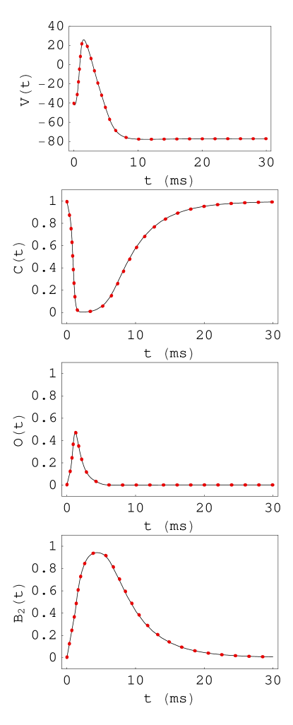
Figure 4:
The action potential solution for a master equation describing single sensor activation of a Na+ channel, Eqs.
(1) to (4), and the current equation, Eq. (17) (solid line) is approximated by the
solution of rate equations for Na+ activation and inactivation, Eqs. (15) and (16), and Eq.
(17) (dotted line), where the rate functions are
, , ,
, ,
, (ms-1), mS/cm2,
mS/cm2, mV, mV, A/cm2.
Figure 5:
A six-state system for Na+ channel gating may be reduced to a five-state system when and .
Figure 6:
The five state system for Na+ channel gating in Fig. 5 may be reduced to a four state system when the and terms in Eqs. (23) and (25) are
an order of magnitude larger than the closed and open state terms.
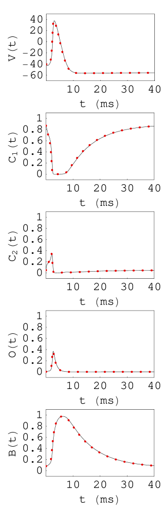
Figure 7:
The action potential solution for a Na+ channel six state master equation, Eqs. (18) to (23) and the current equation, Eq. (46) (solid line) is
approximated by the solution of Eqs. (46) to (48) (dotted line), where the rate functions are
, ,
, , , ,
, , ,
, ,
,, (ms-1),
mS/cm2, mS/cm2, mV, mV, A/cm2.
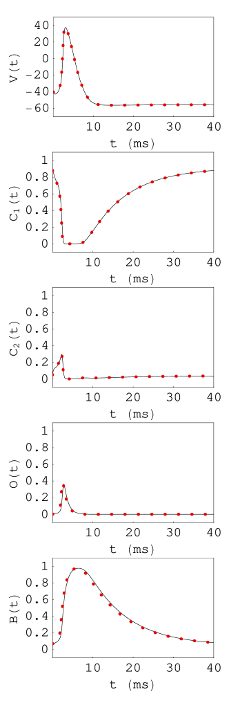
Figure 8:
The action potential solution for a Na+ channel six state master equation with two independant activation sensors, Eqs. (18) to (23) and the current equation,
Eq. (46) (solid line) is approximated by the solution of rate equations for Na+ activation and inactivation and Eq. (46) (dotted line), where the rate functions are
, , , , , ,
, , , , ,
,, (ms-1), mS/cm2, mS/cm2,
mV, mV, A/cm2.
Figure 9:
The 8 state system for Na+ channel gating with 3 sensors may be reduced to a 5 state system when ,
and the transition rates between inactivated states are larger than inactivation and recovery rates.
Figure 10:
The voltage dependence of the Na+ channel HH inactivation rate function , where and
may be approximated by the expressions in Eqs. (84) and (86) where the rate functions
are defined as , ,
, , , , ,
, , , , ,
, ,, ,
, (ms-1), = 120 mS/cm2, = 36 mS/cm2, = 0.3 mS/cm2,
= 55 mV, = -50 mV, = 9 A/cm2.
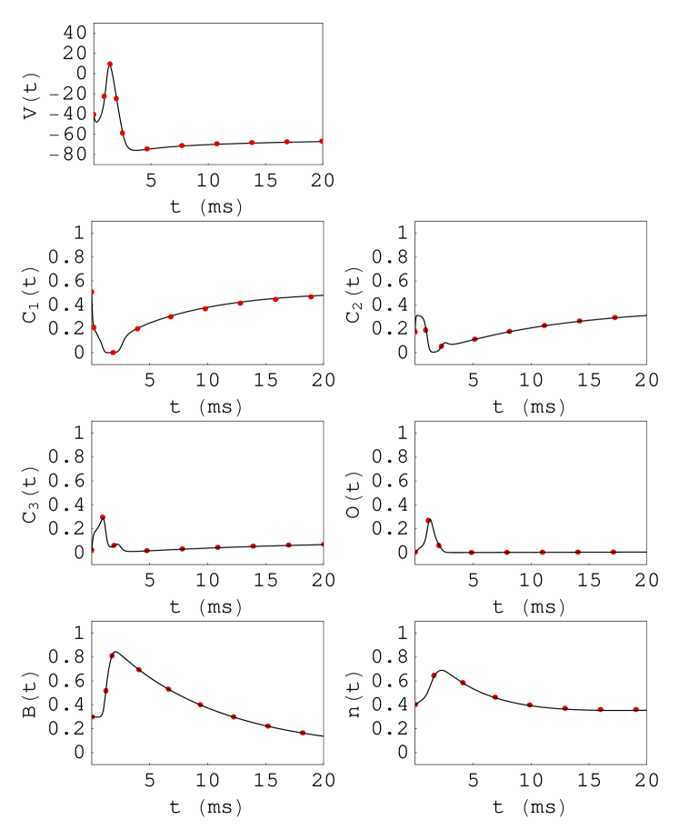
Figure 11:
The solution of a Na+ channel eight state master equation, Eqs. (49) to (56), Eq. (87) and Eq. (88) (solid line) may be approximated by the solution
of Eqs. (83) to Eq. (88) (dotted line), where the rate functions are ,
, , , , , ,
, , , , , ,
,, ,
, (ms-1), = 120 mS/cm2, = 36 mS/cm2,
= 0.3 mS/cm2, = 55 mV, = -50 mV, = 9 A/cm2.
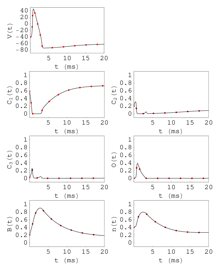
Figure 12:
The solution of a Na+ channel eight state master equation, Eqs. (49) to (56), Eq. (87) and Eq. (88) (solid line) may be approximated by the solution
of Eqs. (83) to Eq. (88) (dotted line), where the rate functions are ,
, , , , , ,
, , , , , ,
, , , ,
, , , ,
(ms-1), = 20 mS/cm2, = 6 mS/cm2, = 2.3 mS/cm2, = 55 mV, = -80 mV,
= -90 mV, = 20 A/cm2.