Transverse contributions to the longitudinal stiffness of the human foot
Abstract
Humans rely on the foot’s stiffness to withstand the propulsive forces of walking and running. The medial longitudinal arch (MLA) and the transverse tarsal arch (TTA) are key adaptations that increase the human midfoot’s longitudinal bending stiffness. The TTA is hypothesized to increase stiffness through a cross-axis coupling between transverse tissue stiffness and longitudinal midfoot stiffness. However, we currently lack in vivo tests of this hypothesis. Such tests are crucial because muscle contraction considerably modulates MLA function and may also affect the TTA’s predicted cross-axis coupling. Here we show in vivo evidence for substantial cross-axis coupling in standing human subjects. We found that longitudinal midfoot bending stiffness increased upon increasing transverse forefoot stiffness using an elastic tape (mean standard error = , p=0.0002), thus supporting the TTA hypothesis. The cross-axis coupling could be a potential therapeutic target for some foot disorders and help augment foot stiffness for athletics.
Keywords: midfoot stiffness, transverse arch, longitudinal arch, transverse stiffness, cross-axis coupling
Introduction
When humans walk and run, the midfoot experiences large sagittal plane bending torques that cause it to bend longitudinally [1]. The foot’s stiffness resists such bending and allows the efficient application of propulsive forces with the forefoot [2]. The medial longitudinal arch (MLA) and the transverse tarsal arch (TTA) are evolved features in human feet that increase midfoot stiffness [3]. Viewed in the sagittal plane, the MLA engages the plantar fascia and other longitudinal tissues, like a bow-and-string, and stiffens the foot [4]. Thus longitudinally oriented tissues affect the foot’s longitudinal stiffness. The TTA is hypothesized to introduce cross-axis coupling by transforming the elastic tissue stiffness along the transverse direction into longitudinal midfoot stiffness [5]. This hypothesized cross-axis coupling between transverse tissue stiffness and longitudinal midfoot stiffness has not been investigated in vivo, and only tested in cadaveric feet.
Cadaveric experiments help understand the baseline stiffness of the foot, and show how passive soft tissue stiffness is transformed into longitudinal midfoot stiffness [4, 6, 5]. Studying passive tissues also impacts our understanding of muscles that share similar lines of action [7, 8]. But cadaveric studies do not present the complete picture. Muscles have complex attachments that are not all parallel to other passive tissues and muscle contraction could substantially alter the contribution of the passive tissues. Such modulation is known from in vivo measurements of MLA function in static [9, 7, 10] and dynamic conditions [8, 11, 12], but we presently lack in vivo studies that investigate the TTA’s cross-axis hypothesis. So we do not know to what extent the cross-axis coupling found in cadaveric feet applies when the foot’s muscles are also actively engaged in load bearing.
Cross-axis coupling hypothesis
The mechanical principle for the hypothesized cross-axis coupling due to the TTA is similar to stiffening a pizza or a thin sheet of paper by slightly curling it. Because of the TTA’s curvature, trying to longitudinally bend the midfoot in the sagittal plane engages the intermetatarsal tissues that resist splaying in the transverse direction. This was shown in cadaveric tests by surgically incising the transverse intermetatarsal tissues, whereupon the longitudinal foot stiffness decreased by over 40% [5]. We cannot use such interventions in vivo to decrease the transverse stiffness, but we can increase it through external means like wrapping an elastic tape around the forefoot (figure 1a). The TTA-induced cross-axis coupling would then manifest as increased longitudinal foot stiffness.
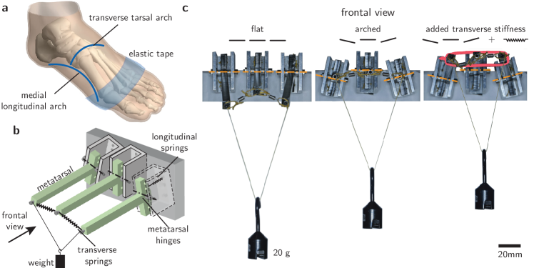
The cross-axis coupling can be demonstrated using a mechanical model of the mid and forefoot regions [5, figure 1b]. The model has three metatarsals that are articulated by hinges at their base, and connected to the base and each other by longitudinal and transverse springs, respectively. When the tip is loaded, the hinges rotate and stretch the longitudinal springs. But when there is a transverse arch, the hinge axes are misaligned and cause the metatarsals to splay apart and engage the transverse springs. As previously shown [5], the model with a transverse arch is stiffer than a flat model and deflects lesser under the same distal load (figure 1c). To demonstrate the cross-axis coupling, we apply a transverse elastic band at the tip, whereupon the stiffness of the curved mimic increases even further (figure 1c). Similarly, adding transverse stiffness to the foot using an elastic band around the ball of the foot is predicted to increase the foot’s stiffness and cause it to bend lesser under external loads.
Results
During static weight bearing in eight consenting healthy human volunteers, we measured how the sagittal plane longitudinal bending stiffness of the midfoot changed upon tightly wrapping the forefoot with a stiff elastic tape (figure 2a). In addition to the taped and free conditions, we used a sham condition of a lightly applied tape as a negative control group. Live animated visual feedback provided to the subject during the trials showed the actual and allowed tolerances for the vertical load magnitude and center of pressure (Methods).
We quantified the change in stiffness using two different but related methods (Methods Section E). First, following standard practice [13], we measured the foot’s mid-dorsum height when the subject was standing with half their bodyweight supported on the ball of the foot. If the midfoot bending stiffness increased, it would bend lesser under the half bodyweight forefoot load and the normalized height difference would be greater than zero. Second, we measured the incremental change in mid-dorsum height when a perturbative midfoot torque was applied in addition to the baseline half bodyweight load. We did this using the windlass mechanism (figure 2a), wherein toe dorsiflexion induces a sagittal plane bending torque at the midfoot [14, 10]. A stiffer foot would show a smaller height change for equal hallux dorsiflexion (figure 2b), and thus the midfoot stiffness is inversely proportional to . We used the measured in the different taping conditions to estimate the normalized stiffness change according to (M2).
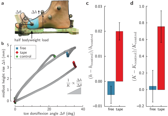
Tape was a significant factor for the ANOVAs on mid-dorsum height and the perturbative stiffness ( and , respectively). With half bodyweight on the ball of the foot, the normalized mid-dorsum height change is significantly greater than zero in the taped condition (mean standard error=), but not in the free condition (mean standard error=). The normalized midfoot stiffness change that is estimated using the perturbative windlass torque was also significantly greater than zero for the taped condition (mean standard error=), but not for the free condition (mean standard error=). Therefore, transversally taping the forefoot significantly increased the longitudinal midfoot stiffness (figure 2c,d).
Discussion
We have shown that the cross-axis coupling found in cadaveric studies is also effective under in vivo conditions despite the likely engagement of the foot’s muscles for load bearing. But this should not be interpreted to mean that muscles cannot or do not modulate the TTA’s contribution. The tibialis posterior, which is known to affect MLA deformation [15, 16, 17], also inserts into the tarsal bones and into multiple proximal metatarsal areas that are part of the TTA’s structure. Indeed, simulated tibialis posterior contraction has been previously reported to alter the TTA shape in cadaveric tests [16]. The intrinsic dorsal interossei and adductor hallucis muscles could also be important because they have transverse lines of action [18], and their contraction could make use of the TTA-induced cross-axis coupling by altering the intermetatarsal stiffness. Nevertheless, our measurements show that the cross-coupling that is seen in cadaveric feet carries over to bodyweight support in standing. Modulation of the TTA’s cross-axis coupling by muscle contraction is probably used during dynamic conditions of locomotion but further studies are needed to test these hypotheses.
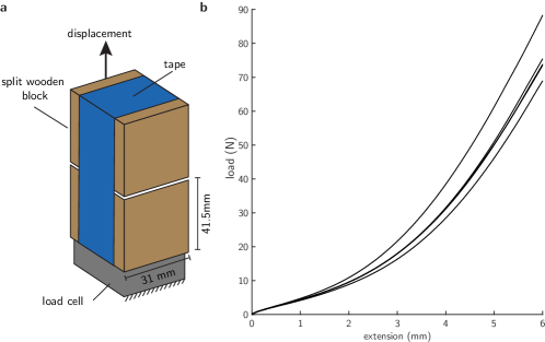
The inter-subject variability in our data may arise from several factors, including the TTA’s anatomical variability, the tape wrapping method’s repeatability, and the tape application location relative to the effective midfoot bending axis. Future studies that include radiographic TTA measurements are needed to assess whether TTA curvature differences account for inter-subject variability even if the tape stiffness is equal. To verify that the tape wrapping protocol was repeatable, we wrapped tape around a dummy model made of two wooden blocks and measured the stiffness added by the tape in multiple repetitions (figure 2 – figure supplement 1). But mathematical analysis of a previously derived model for a mechanical foot-like device reveals another possible source of variability. In that model, the longitudinal bending stiffness depends on the square of the antero-posterior distance between the metatarsal hinges and the transverse springs at the distal end [equations (S4.3) and (S4.4) in 5]. Therefore, small variability in the antero-posterior placement of the transverse springs relative to the hinges will be amplified at least two-fold when it maps to variability of the longitudinal bending stiffness. We expect a similar issue with the antero-posterior tape location. Although the experimenter used clear bony landmarks of the distal metatarsal heads to wrap the tape, there is unknown variability in the anatomical equivalent of the midfoot hinge. This is because midfoot anatomy is comprised of complex multi-articular arrangement of bones so that a simple hinge-like midfoot joint cannot be identified. The effective midfoot center of rotation may lie somewhere between the tarsometatarsal joints and the subtalar joint, although it is probably close to the mid-dorsum area [19]. This region occupies a substantial fraction of the foot’s length and thus natural anatomical variability may lead to considerable variability in how the elastic tape’s stiffness is transformed into longitudinal midfoot bending stiffness. Thus, refinements to the protocol for increasing transverse stiffness could help reduce the inter-subject variability and are left for the future.
There are several potential applications of our work in foot health and athletics. Adult acquired flatfoot disorders [17], specially in patients with advanced diabetes [20, 21], could cause significant impairment to locomotion ability. Future clinical studies are needed but non-invasive foot taping could serve as a strategy to manage these conditions. Foot taping in therapeutic settings reduces MLA deformation during quiet standing or walking [22, 23], even for people with flat longitudinal arches [24]. Unlike our taping method, these studies applied tape all over the foot, including the midfoot and proximal regions around the heel. In patients with vascular issues, such as the case with diabetes, reducing the amount of compressive taping may be desirable. Our results show that increasing transverse stiffness in the bony regions at the ball of the foot is sufficient, which could be better suited for patients with vascular issues than taping the whole foot. Similarly, athletic performance in sports may depend on foot stiffness [25], and a stiff distal tape may augment midfoot stiffness without adding much weight.
Methods
A Informed consent
We performed human subject experiments with 8 healthy, consenting volunteers. The cohort included 5 females and 3 males of age 30 years 8.4 years (mean standard deviation). Subject-wise age, weight, gender and foot size measurements are available in figure 2 – source data 1. Before the start of the experiment, the subjects studied the informed consent form and the experimenter discussed potential risks of the study and their option to withdraw from the study at any time. The experiment was started after the subject agreed to participate in the study. The detailed procedures for seeking informed consent were approved by Yale University’s IRB.
B Experimental apparatus
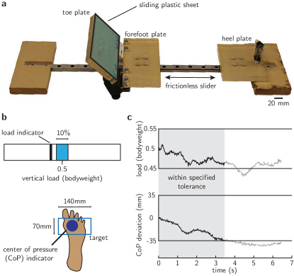
During the study, the subjects stood with one foot on a custom rig. The rig’s platform has a fixed heel support, a forefoot support that is free to move in the antero-posterior direction, and a toe dorsiflexion plate attached to the forefoot support with a lockable hinge (figure M1a). The experimenter used the toe plate to dorsiflex the toes and engage the windlass to apply a perturbative midfoot torque. A sliding plastic sheet on the toe plate reduced friction and skin shear at the toe. The other foot rested neutrally on an adjacent force plate, with the height adjusted so that both feet were on the same level.
C Data collection
With the subject standing on ground, we used calipers to measure the truncated foot length as the length from the posterior calcaneal tuberosity to the first metatarsophalangeal joint, and the forefoot width as the medio-lateral distance between the distal heads of the first and fifth metatarsals. In each trial, we recorded 3D kinematics of 8 landmarks: first distal interphalangeal joint, medial and lateral malleoli, first and fifth metatarsophalangeal joints, navicular tuberosity, the posterior calcaneal tuberosity inferior to the Achilles tendon insertion, and the foot’s mid-dorsum. The mid-dorsum is defined as the point on the dorsal surface of the foot directly above the midpoint of the foot length [26, 27, 13]. These landmarks were tracked using retro-reflective markers and motion capture cameras at 50 Hz (Vicon Ltd. model T20S, Oxford, UK), and foot forces were recorded using a six-axis force plate at 1000 Hz (AMTI Inc. model BP600900, Watertown MA).
Subjects received real-time animated feedback on a computer screen that was positioned in front of them (figure M1b). The visual feedback displayed the vertical force magnitude on the foot being tested (black bar), and the center of pressure relative to the foot (circular dot). The foot outline in figure M1b is for the reader’s benefit, and the subject could only see a box and a dot. The feedback helped to ensure that (i) the load magnitude was within 10% of half bodyweight, and (ii) the center of pressure was within a 140 mm by 70 mm forefoot region. Before starting each trial, subjects were asked to balance on the ball of the foot, while we recorded the mean center of pressure location using which the constraining rectangle was centered. Subjects were then instructed to load the ball of the foot with half their bodyweight, and maintain the center of pressure within the bounding rectangle for the entire trial. Data points were used for analyses when the vertical force magnitude and the center of pressure indicators were both within the specified range (e.g. gray highlighted regions in M1c).
The foot was tested under three conditions: (i) free foot with no tape, (ii) taped foot with an elastic tape wrapped tightly around the distal metatarsal heads, and (iii) control foot with the elastic tape loosely applied with as little tension as possible. The length of the tape was customized for each subject to match the circumference of the unloaded forefoot. For the taped condition it was stretched to the maximum extent possible by hand and wrapped tightly (same experimenter for all subjects). In the control condition, the tape was wrapped at the forefoot without perceivable stretch. The foot was held unloaded at the time of application of the tape in the taped and control conditions. We used commonly available adhesive Kinesiology tape (3B Scientific, Hamburg, Germany and VARA Tape, NY, USA).
The added stiffness due to the elastic tape was measured and the repeatability of the experimenter’s skill was assessed using dummy models in a materials testing machine (Instron model 3345, Norwood, MA). The dummy forefoot comprised of two wooden blocks of 41.5 mm length and 31 mm width (figure 2 – figure supplement 1a), whose dimensions are based on typical measurements of a human forefoot. Five samples of the tape (3B Scientific, Hamburg, Germany) were tested by the same experimenter who performed the human subject trials. The following protocol was used while measuring the force and displacement at 50 Hz:
-
1.
The blocks were rigidly clamped in a materials testing machine (Instron model 3345, Norwood, MA).
-
2.
A small initial separation between the blocks was chosen to allow a sheet of paper to easily slide between them (approximately 0.1 mm).
-
3.
Tape of length 230 mm was wrapped around the blocks after which the load cell and the displacement sensor were both zeroed.
-
4.
The block separation was cycled between 0 and 60 mm using constant rate ramps of 0.16 mm/s. Higher displacements were avoided as the tape started to peel away.
-
5.
Based on pilot trials, four loading-unloading cycles were performed for each sample to allow the tape’s elastic material to settle into a steady-state and the fifth loading cycle is reported. The initial load at the start of the fifth cycle is defined as zero (figure 2 – figure supplement 1b).
The stiffness, defined as the ratio of the total change in load to the total displacement, was 12.67 N/mm1.21 N/mm (meanstandard deviation) in measurements from 5 different wrapping trials (figure 2 – figure supplement 1b).
D Data Analysis
All trials for subject 8, and the right foot of subject 2 were rejected because most data points were outside the specified ranges. The left foot of subject 4 was rejected because the subject reported prior injury to that foot approximately 5 years before the experiment. The right foot of subject 5 was not recorded due to technical glitches. Thus, a total of 11 feet from 7 subjects are reported.
Kinematic data were smoothed by a 1 s moving average filter using a window size of 50 samples. The toes were held at a constant angle for a few seconds at the start and finish of the toe dorsiflexion to make the measurements. Averages from these static phases were used to define the absolute height of the mid-dorsum above foot’s base, the hallux dorsiflexion angle , and change in the height of the mid-dorsum . Kinematic data were registered to a foot-centric origin defined by the average position of the heel, lateral malleolus and medial malleolus markers, thereby adjusting for possible rigid motions of the foot during the trials. Data were processed using Matlab v9.8.0.1323502 (MathWorks Inc., Natick, MA).
E Stiffness quantification
We calculated two surrogates for the change in the sagittal-plane longitudinal bending stiffness of the midfoot. First, following established protocol [13], we measured the absolute height of the mid-dorsum marker above the base of the foot under static half bodyweight load. We used the difference between the test conditions (taped or free) and the control condition as a surrogate for change in stiffness relative to the control. Typically, the change in mid-dorsum height with and without load is used to estimate stiffness. We could not reliably measure the mid-dorsum height of the unloaded foot because the elastic tape caused the forefoot to cup and affected the height measurement under no-load. But because the cupping vanishes upon slightly loading the foot, we are able to compare the height between the taped and free conditions using the negative control of a loosely applied tape. In our protocol, the height difference between the test and control condition is proportional to the stiffness difference plus an unknown baseline that depends on the extent of cupping for that subject. So the stiffness change , where is a proportionality constant and is an unknown per-subject baseline. Based on this, we are able to use to test whether stiffness increased but are unable to directly infer the magnitude of stiffness change because of the unmeasurable per-subject baseline. This limitation motivated our second method to measure stiffness change.
In the second method, we applied a perturbative midfoot torque in addition to the half bodyweight load by using the windlass mechanism within the foot [14, 10]. The plantar fascia in human feet extends from the calcaneus all the way to the toes. So toe dorsiflexion would stretch the plantar fascia and induce a sagittal-plane torque at the midfoot. We dorsiflexed the toes using the lockable toe plate (figure M1a) and measured the change in the mid-dorsum height and the hallux dorsiflexion angle . The perturbation magnitude is proportional to the hallux dorsiflexion angle . The change in the mid-dorsum height divided by the perturbation magnitude is directly proportional to the longitudinal midfoot compliance or the reciprocal of stiffness . Therefore, we are able to infer that
| (M1) | ||||
| (M2) |
F Statistical methods
We performed two Type-III one-way analyses of variance (ANOVA) with Satterthwaite’s method using and as the response variables to test the effect of applying the forefoot tape. The ANOVAs were posed as a linear mixed model with condition (control, tape, free) as the fixed factor and subject as random factor with foot side (left, right) nested within subject, and repetition number (1,2) nested within foot side. Significance level for all statistical tests was set at 0.05. If the ANOVA was significant, we performed a Tukey all-pairs comparison test with Holm-Bonferroni correction, and report the mean and standard error of the mean for the post-hoc comparisons. Statistical tests were performed in R (v4.0.3) [28], the ANOVA was performed using the lme4 v1.1.25 and lmerTest v3.1.3 packages, and post-hoc comparisons were performed using the multcomp v1.4.15 package.
Acknowledgments
Volunteers for participation, and Nick Bernardo, Dylan Shah, and the Yale Center for Engineering Innovation and Design for fabrication and mechanical testing support.
Competing interests
The authors declare no competing financial interests.
Funding
This work was funded by the Human Frontier Science Program.
Author contributions
MV and SM conceived of the study. AY and LK conducted the human subject experiments with guidance from MV. AY analyzed the data and performed statistics in consultation with MV. AY and MV wrote the manuscript, and all authors contributed edits.
References
- [1] Bruening, D. A., Cooney, K. M. & Buczek, F. L. Analysis of a kinetic multi-segment foot model part ii: kinetics and clinical implications. Gait & posture 35, 535–540 (2012).
- [2] Ray, S. F. & Takahashi, K. Z. Gearing up the human ankle-foot system to reduce energy cost of fast walking. Scientific reports 10, 1–12 (2020).
- [3] Holowka, N. B. & Lieberman, D. E. Rethinking the evolution of the human foot: insights from experimental research. Journal of Experimental Biology 221, jeb174425 (2018).
- [4] Ker, R. F., Bennett, M. B., Bibby, S. R., Kester, R. C. & Alexander, R. M. The spring in the arch of the human foot. Nature 325, 147–149 (1987).
- [5] Venkadesan, M. et al. Stiffness of the human foot and evolution of the transverse arch. Nature 579, 97–100 (2020).
- [6] Huang, C.-K., Kitaoka, H. B., An, K.-N. & Chao, E. Y. Biomechanical evaluation of longitudinal arch stability. Foot & Ankle International 14, 353–357 (1993).
- [7] Kelly, L. A., Cresswell, A. G., Racinais, S., Whiteley, R. & Lichtwark, G. Intrinsic foot muscles have the capacity to control deformation of the longitudinal arch. Journal of The Royal Society Interface 11, 20131188 (2014).
- [8] Kelly, L. A., Lichtwark, G. & Cresswell, A. G. Active regulation of longitudinal arch compression and recoil during walking and running. Journal of The Royal Society Interface 12, 20141076 (2015).
- [9] Kelly, L. A., Kuitunen, S., Racinais, S. & Cresswell, A. G. Recruitment of the plantar intrinsic foot muscles with increasing postural demand. Clinical biomechanics 27, 46–51 (2012).
- [10] Welte, L., Kelly, L. A., Lichtwark, G. A. & Rainbow, M. J. Influence of the windlass mechanism on arch-spring mechanics during dynamic foot arch deformation. Journal of the Royal Society Interface 15, 20180270 (2018).
- [11] Farris, D. J., Kelly, L. A., Cresswell, A. G. & Lichtwark, G. A. The functional importance of human foot muscles for bipedal locomotion. Proceedings of the National Academy of Sciences 116, 1645–1650 (2019).
- [12] Holowka, N. B., Richards, A., Sibson, B. E. & Lieberman, D. E. The human foot functions like a spring of adjustable stiffness during running. Journal of Experimental Biology 224 (2021).
- [13] Butler, R. J., Hillstrom, H., Song, J., Richards, C. J. & Davis, I. S. Arch height index measurement system: establishment of reliability and normative values. Journal of the American Podiatric Medical Association 98, 102–106 (2008).
- [14] Hicks, J. The mechanics of the foot: II. The plantar aponeurosis and the arch. Journal of Anatomy 88, 25 (1954).
- [15] Johnson, K. A. & Strom, D. E. Tibialis posterior tendon dysfunction. Clinical Orthopaedics and Related Research (1976-2007) 239, 196–206 (1989).
- [16] Kitaoka, H. B., Luo, Z. P. & An, K.-N. Effect of the posterior tibial tendon on the arch of the foot during simulated weightbearing: biomechanical analysis. Foot & ankle international 18, 43–46 (1997).
- [17] Kohls-Gatzoulis, J. et al. Tibialis posterior dysfunction: a common and treatable cause of adult acquired flatfoot. BMJ: British Medical Journal 329, 1328 (2004).
- [18] Kura, H., Luo, Z.-P., Kitaoka, H. B. & An, K.-N. Quantitative analysis of the intrinsic muscles of the foot. The Anatomical Record: An Official Publication of the American Association of Anatomists 249, 143–151 (1997).
- [19] Ito, K. et al. Three-dimensional innate mobility of the human foot bones under axial loading using biplane x-ray fluoroscopy. Royal Society open science 4, 171086 (2017).
- [20] Hastings, M. K. et al. Kinematics and kinetics of single-limb heel rise in diabetes related medial column foot deformity. Clinical Biomechanics 29, 1016–1022 (2014).
- [21] Gelber, J. R. et al. Windlass mechanism in individuals with diabetes mellitus, peripheral neuropathy, and low medial longitudinal arch height. Foot & Ankle International 35, 816–824 (2014).
- [22] Ator, R., Gunn, K., McPoil, T. G. & Knecht, H. C. The effect of adhesive strapping on medial longitudinal arch support before and after exercise. Journal of Orthopaedic & Sports Physical Therapy 14, 18–23 (1991).
- [23] Yoho, R., Rivera, J. J., Renschler, R., Vardaxis, V. G. & Dikis, J. A biomechanical analysis of the effects of low-dye taping on arch deformation during gait. The foot 22, 283–286 (2012).
- [24] Bishop, C., ARNOLD, J. & May, T. Effects of taping and orthoses on foot biomechanics in adults with flat-arched feet. Medicine & Science in Sports & Exercise 48, 689–696 (2016).
- [25] Brinkmann, D. J., Koerger, H., Gollhofer, A. & Gehring, D. Effect of forefoot and midfoot bending stiffness on agility performance and foot biomechanics in soccer. Journal of Applied Biomechanics 1, 1–7 (2020).
- [26] Saltzman, C. L., Nawoczenski, D. A. & Talbot, K. D. Measurement of the medial longitudinal arch. Archives of Physical Medicine and Rehabilitation 76, 45–49 (1995).
- [27] Williams, D. S. & McClay, I. S. Measurements used to characterize the foot and the medial longitudinal arch: reliability and validity. Physical Therapy 80, 864 (2000).
- [28] R Core Team. R: A Language and Environment for Statistical Computing. R Foundation for Statistical Computing, Vienna, Austria (2020). URL https://www.R-project.org/.
Figure supplement