New High-Precision Drift-Tube Detectors for the ATLAS Muon Spectrometer
Abstract
Small-diameter muon drift tube (sMDT) detectors have been developed for upgrades of the ATLAS muon spectrometer. With a tube diameter of 15 mm, they provide an about an order of magnitude higher rate capability than the present ATLAS muon tracking detectors, the MDT chambers with 30 mm tube diameter. The drift-tube design and the construction methods have been optimised for mass production and allow for complex shapes required for maximising the acceptance. A record sense wire positioning accuracy of m has been achieved with the new design. 14 new sMDT chambers are already operational in ATLAS, further 16 are under construction for installation in the 2019-2020 LHC shutdown. For the upgrade of the barrel muon spectrometer for High-Luminosity LHC, 96 sMDT chambers will be contructed between 2020 and 2024.
1 Introduction
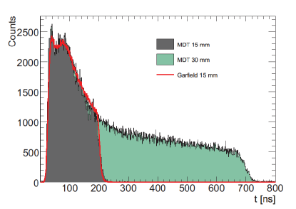
The ATLAS Monitored drift tube (MDT) chambers [1] provide reliable muon tracking with excellent spatial resolution and high tracking efficiency independent of the track incident angle. Small-diameter muon drift tube (sMDT) chambers with a tube diameter of 15 mm, i.e. half of the tube diameter of the MDT chambers, have been developed to cope with the higher background irradiation rates at High-Luminnosity LHC (HL-LHC) and future hadron colliders and to fit into small available spaces as it is necessary for the upgrades of the ATLAS muon spectrometer. At the same time, the chamber construction methods have been optimised for mass production with significant savings in component cost, construction time and manpower compared to the ATLAS MDT chambers while providing the same reliability and mechanical robustness and even higher sense wire positioning accuracy. For the ATLAS precision muon tracking detectors a wire positioning accuracy of m (rms) is required. Standard aluminium tubes are used, with a wall thickness of 0.4 mm like for the MDT chambers. The sMDT chambers are operated in ATLAS with the same gas mixture, gas pressure and gas gain as the MDT chambers. Table 1 shows a comparison of the MDT and sMDT operating parameters. The drift time spectra are shown in the left-hand part of figure 1. The maximum drift time of the sMDT tubes is only 175 ns compared to about 720 ns of the MDT chambers leading, together with the twice smaller cross section exposed to the radiation, to about 8 times lower occupancy and a linear space-to-drift time relationship with the standard MDT drift gas Ar:CO2 (93:7) at 3 bar pressure.
| Type | MDT | sMDT |
|---|---|---|
| Tube material | Aluminium | Aluminium |
| Aluman100 | AW 6060-T6/ AlMgSi | |
| Tube innerouter surface | Surtec 650 chromatisation | |
| Tube outer diameter | 29.970 mm | 15.000 mm |
| Tube wall thickness | 0.4 mm | 0.4 mm |
| Wire material | W-Re (97:3) | W-Re (97:3) |
| Wire diameter | m | m |
| with gold plating, thickness | ||
| Wire resistance/m | m | m |
| Wire pitch | 30.035 mm | 15.099 mm |
| Wire tension | g | g |
| Gas mixture | Ar:CO2 (93:7) | Ar:CO2 (93:7) |
| Gas pressure | 3 bar (abs.) | 3 bar (abs.) |
| Gas gain | ||
| Wire potential | 3080 V | 2730 V |
| Maximum drift time | 720 ns | 175 ns |
| Average tube spatial resolution | m | m |
| without backgr. irradiation | ||
| Average tube spatial resolution | m | m |
| at 500 Hz/cm2 backgr. rate | ||
| Drift tube muon efficiency | ||
| without backgr. irradiation | ||
| Drift tube muon efficiency | ||
| at 200 kHZ/tube backgr. rate | ||
| Wire positioning accuracy | m (rms) | m (rms) |
 |
 |
 |
|
 |
 |
 |
 |
A full-scale sMDT prototype chamber of trapezoidal shape has been constructed and tested in the H8 muon beam and in the Gamma Irradiation Facility (GIF) at CERN in 2010 [4]. The chamber has been operated in the ATLAS cavern in 2012. In 2014, two sMDT chambers [5], each with two integrated RPC chambers, have been installed in access shafts in the feet region of the ATLAS barrel muon spectrometer (so-called BME chambers) and are in operation since the start of LHC run 2. In January 2017, 12 new sMDT chambers have been installed inside the detector feet in the bottom sectors of the barrel muon spectrometer (so-called BMG chambers) [5, 6, 7] and are in operation for the new data taking in 2017.
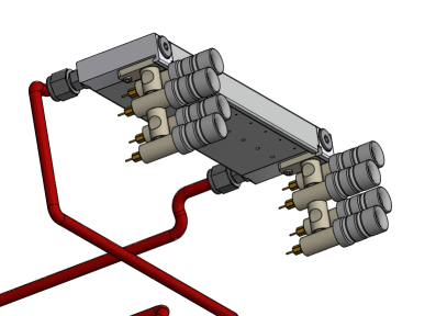
The construction of further 16 sMDT chambers with integrated triplet RPC trigger chambers (see figure 10) has started. They will be installed under very tight spatial constraints on the toroid magnet coils at the ends of the inner barrel layers (so-called BIS chambers) in the long LHC shutdown in 2019-2020 in order to improve the trigger efficiency and the rate capability of the chambers in the transition regions between barrel and endcaps. They have rather complex shapes in order to maximise the acceptance in the overlap region between the barrel part the muon spectrometer and the inner endcap layer and can only be built with the assembly methods developed for the sMDT chambers. This upgrade of the muon spectrometer serves as pilot project for the complete replacement of the MDT chambers in the by sMDT-RPC chamber modules enhancing the rate capability of the tracking and trigger chambers by about an order of magnitude and increasing the barrel muon trigger efficiency and robustness for operation at HL-LHC. The installation of new triple thin-gap RPCs of only 5 cm thickness becomes possible only by replacing the BIS MDT chmabers by sMDT chambers which have about half the height. 96 new BIS sMDT chambers will be constructed for this purpose in the years 2020-2024.
2 Performance of the sMDT chambers
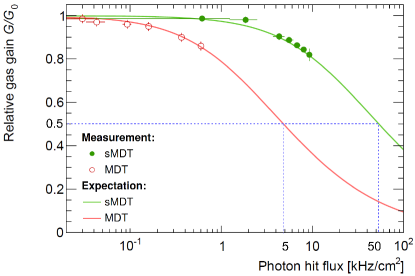
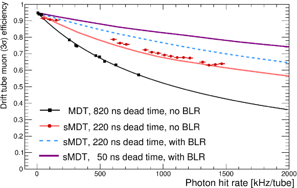
The performance of MDT [3] and sMDT chambers [2] has been extensively studied at the Gamma Irradiation Facility at CERN using the existing ATLAS MDT readout electronics with bipolar shaping. For the (s)MDT amplifier-shaper-discriminator (ASD) chips at HL-LHC the same specifications will be used as for the present system. The MDT chambers can be operated up to background rates of 500 Hz/cm2 and 300 kHz per tube. At background rates above 500 Hz/cm2, the gas gain drops by more than (see figure 1, right) leading, together with the effect of space charge fluctuations, to rapid deterioration of the spatial resolution with increasing background flux. The limitations of the MDT chambers are overcome by using drift tubes with half the diameter of the ATLAS MDT tubes while leaving the operating parameters, Ar:CO2 (93:7) gas mixture at 3 bar pressure and nominal gas gain of 20000 (for a wire potential with respect to the tube wall of 2730 V in sMDT tubes), unchanged [2].
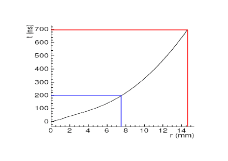
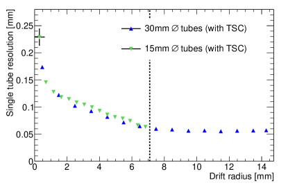
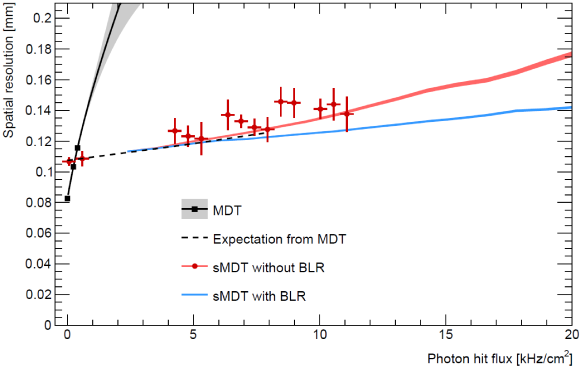
As the space charge density inside the drift tubes is proportional to the third power of the tube radius, 15 mm diameter drift tubes show a significant gain drop only at 8 times higher background rates compared to 30 mm diameter drift tubes (see figure 1, right). At the same time, the deteriorating effect of space charge fluctuations on the spatial resolution is eliminated because the drift gas is linear to good approximation for drift radii below 7.5 mm (see figure 2, left). The radial dependence of the spatial resolution of 15 and 30 mm diameter drift tubes from measurements in the H8 muon beam at CERN without radiation background is shown in the right-hand part of figure 2 [8]. Standard MDT time-slewing corrections are applied in both cases. Without irradiation and associated space charge effects and with time-slewing corrections, the average sMDT drift tube resolution is m compared to m for the MDTs [8]. The dependence of the average spatial resolution of MDT and sMDT drift tubes on the background rate is shown in figure 3. The spatial resolution deteriorates quickly with increasing background flux for the MDTs while it is affected only little by space charge effects up to very high irradiation rates for the sMDTs.
At the same background rate, the small-diameter drift tubes experience 8 times lower occupancy than the 30 mm diameter MDT tubes because of the 4 times shorter maximum drift time (see figure 1) and the twice smaller tube cross section exposed to the radiation. Because of the much shorter maximum drift time, the dead time of the MDT readout electronics (which for the MDTs is set to a nominal value of 820 ns, slightly above the maximum drift time, to prevent the detection of secondary ionization clusters) can be reduced to the minimum adjustable value of 220 ns, just above the maximum drift time of the sMDT tubes. In this way, the masking of muon hits by preceding background pulses is strongly reduced increasing the muon detection efficiency defined as the probability to find a hit on the extrapolated muon track within 3 times the drift tube resolution ( efficiency). Figure 4 shows the improvement of the efficiency of sMDT tubes at high background counting rates compared to the MDT tubes. Muon track segment reconstruction efficiencies of almost and a spatial resolution of better than m are achieved with 8-layer sMDT chambers at the maximum background rates expected at HL-LHC.
3 Drift tube design and fabrication
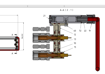
The sMDT chamber design and construction procedures have been optimized for mass production while they provide highest mechanical accuracy in the sense wire positioning. Standard industrial aluminium tubes with 15 mm outer diameter and a wall thickness of 0.4 mm are used. The tubes are chromatised on the in- and outside for the cleaning purposes and reliable electrical ground contact. The ground pins are screwed into the holes between adjacent tube triplets during the glueing of the tube layers (see figure 6). The drift tube design and fabrication procedures are the same as used for the construction of the BMG sMDT chambers in 2016 [6, 7].
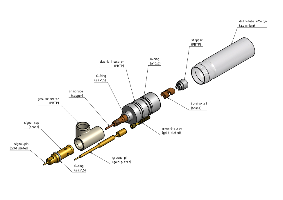
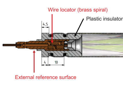
The drift tubes are assembled using a semi-automated wiring station in a temperature-controlled clean room. The endplugs are inserted into the tubes and the sense wires fed through the tubes and the endplugs by means of air flow without manual contact. Afterwards the endplugs are fixed and and the tubes gas sealed by swaging. Finally, the wires are fixed in copper crimp tubelets inserted in the endplug central pins after tensioning them to g, corresponding to a gravitational sag of only m (absolute tolerances) for 1 m long tubes, including overtensioning to 430 g for 10 s. The wires are positioned at each tube end with a few micron precision with respect to a cylindrical external reference surface on the central brass insert of the endplug which also holds the spiral shaped wire locator on the inside of the tube. The drift tubes are sealed with the endplugs using two O-rings per endplug and mechanical swaging of the tube walls. For the injection molded endplug insulators and gas connectors for the individual tubes, plastic materials with minimum outgassing have been selected which are also immune against cracking.
Only materials already certified for the ATLAS MDT chambers are used for sMDT drift tubes and their gas connections in order to prevent ageing. No outgassing of the plastic materials of endplugs (PBTP Crastin LW9330, reinforced with 30% glass fiber) and gas connectors (PBTP Crastin S600F20, unreinforced) has been observed. The sMDT tubes, including the plastic material of the endplugs, have been irradiated with a 200 MBq 90Sr source over a period of 4 months with a total charge accumulation on the sense wire of 9 C/cm without any sign of aging [8, 10].
Typical production rates of 100 tubes per day have been achieved with one assembly station operated by two technicians at an average failure rate of about , which is mostly due to occasional failures of the assembly devices. During the production of the 4300 BMG drift tubes, the failure rate of the standard drift tube quality tests of wire tension ( g), gas leak rate ( bar l/s) and leakage current ( nA/m) at the nominal operating voltage of 2730 V was only , mostly due to too high dark currents under high voltage.
4 sMDT chamber construction and test
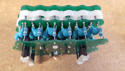
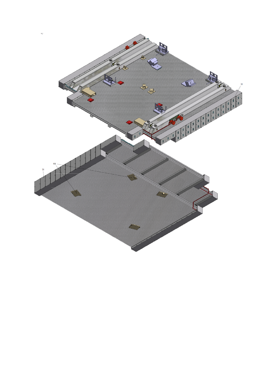
After passing the quality assurance tests, the drift tubes are assembled to chambers in a climatised clean room by inserting the endplug reference surfaces into a grid of fitting bores in the assembly jigs at each chamber end which define the wire positions with an accuracy of better than m and glueing them together and to the spacer and support frame using an automated glue dispenser. A complete chamber can be assembled within two working days, including the precise mounting of the global alignment sensor platforms. The same two-component expoxy glues as for the MDT chamber construction are used, Araldite 2014 between the tube layers and DP 490 between multilayers and spacer and support structures. After the glueing of each new tube layer, ground connection screws are inserted into the triangular gaps between adjacent tube layers through holes in the jig, scratching the chromatised tube walls. The gaps are filled with glue during the assembly of the next layer, fixing and encapsulating the ground screws. Conducting glue may be added in order to improve the conductivity of the ground connection if necessary. After mounting of the gas connections, ground pins connecting to the readout and high-voltage distribution boards are screwed onto the ground screws (see figure 7).
Like the BME sMDT chambers, but in contrast to the BMG chambers, the BIS7/8 and BIS 1-6 sMDT chambers will have in-plane alignment monitoring systems. The longitudinal sag monitors of the in-plane alignment system of the BIS 7/8 chambers is rotated by 180∘ with respect to the standard orientation parallel to the tube direction in the MDT and also the BME and BIS 1-6 chambers in order to properly monitor potential deformations of the complex shaped chambers transverse to the tubes. Two diagonal straightness monitors measure torsions between the readout and high-voltage ends in all types of chambers. Like the MDT chambers, the BME and BIS sMDT chambers carry an optical alignment system monitoring the planarity of the chambers. The BMG and BIS sMDT chambers carry in addition optical sensors for the alignment of the chambers with respect to neighboring chambers, which are mounted on the tube layers with m positioning accuracy with resepct to the sense wires during chamber assembly (see figure 10).
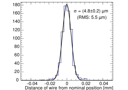
After the glueing of the tube layers, the positions of the individual endplug reference surfaces and, thus, of the sense wires are measured at the two chamber ends with an automated coordinate measuring machine with a precision of about m. The measurement was performed within 1-2 hours for every BME and BMG chamber and is planned as regular spot check during the BIS chamber serial production. In particular, the positions of the alignment sensor platforms with respect to the wire grid can be measured with a few micron accurracy. Sense wire positioning accuracies of better than m (rms) have been routinely achieved during BME and BMG chamber construction [5, 6]. An ultimate wire positioning accuracy of m (rms) has been achieved in the BMG chamber construction, which comes close the precision of the assembly jigs (see figure 8). All BMG sMDT chambers have a wire positioning accuracy of better than m with an average of m. After the measurement, the individual wire positions are known with m accuracy.
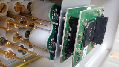
After the wire position measurement, the parallel gas distribution system is mounted, consisting of modular injection molded plastic gas connectors connecting tubes in columns perpendicular to the chamber plane to the chromatised aluminium gas distribution bars (see figures 6 and 9). Gas leak rates at 3 bar pressure below the limit of bar l/s required for a chamber with n tubes have been achieved for all BMG chambers [6].
5 sMDT chamber electronics
After the installation of the gas distribution system, ground pins and Faraday cages, the high-voltage and the signal distribution boards (see figure 7) as well as the active readout electronics (mezzanine) cards with 6 x 4 channels matching the transverse cross section of the quadruple-multilayers are mounted on opposite ends of the chambers. The decoupling capacitors on the RO side and the terminating resistors on the HV side are enclosed in plastic containers in order to guarantee HV stability. The mezzanine cards, stacked on top of the signal distribution boards, contain three 8-channel amplifier-shaper discriminator (ASD) chips and a TDC chip for drift time measurement which provide the same functionality as the standard MDT readout electronics.
References
- [1] The ATLAS collaboration, G. Aad et al., The ATLAS Experiment at the Large Hadron Collider, J.Instr. 3 (2008) S08003.
- [2] B. Bittner et al., Development of Muon Drift-Tube Detectors for High-Luminosity Upgrades of the Large Hadron Collider, Nucl. Instr. and Meth. A617 (2010) 169.
- [3] M. Deile et al., Resolution and Efficiency of the ATLAS Muon Drift-Tube Chambers at High Background Rates, Nucl. Instr. and Meth. A535 (2004) 212; S. Horvat et al., Operation of the ATLAS Muon Drift-Tube Chambers at High Background Rates and in Magnetic Fields, IEEE Trans. Nucl. Sci. 53, no. 2 (2006) 562.
- [4] H. Kroha et al., Construction and Test of a Full-Scale Prototype Drift-Tube Chamber for the Upgrade of the ATLAS Muon Spectrometer at High LHC Luminosities, Nucl. Instr. and Meth. A718 (2013) 427.
- [5] C. Ferretti, H. Kroha (on behalf of the ATLAS Muon Collaboration), Upgrades of the ATLAS Muon Spectrometer With sMDT Chambers, Nucl. Instr. and Meth. A 824 (2016) 538.
- [6] H. Kroha et al., Construction and Test of New Precision Drift Tube Chambers for the ATLAS Muon Spectrometer, Nucl. Instr. and Meth. A, doi:10.1016/j.nima.2016.05.091.
- [7] H. Kroha et al., Performance of New High-Precision Muon Tracking Detectors for the ATLAS Experiment, arXiv:1701.08971, November 2016.
- [8] B. Bittner et al., Performance of Drift-Tube Detectors at High Counting Rates for High-Luminosity LHC Upgrades, Nucl. Instr. Meth. A732 (2013) 250.
- [9] S. Nowak et al., Optimisation of the Read-out Electronics of Muon Drift-Tube Chambers for Very High Background Rates at HL-LHC and Future Colliders, arXiv:1603.08841, November 2015.
- [10] O. Kortner et al., Precision Muon Tracking Detectors and Read-Out Electronics for Operation at Very High Background Rates at Future Colliders, Nucl. Instr. and Meth. A824 (2016) 556.