June 16, 2016
Sympathetic Cooling Simulations with a Variable Time Step
Abstract
In this paper we present a new variable time step criterion for the velocity-Verlet algorithm allowing to correctly simulate the dynamics of charged particles exchanging energy via Coulomb collisions while minimising simulation time. We present physical arguments supporting the use of the criterion along with numerical results proving its validity. We numerically show that ions with 18 meV initial energy can be captured and sympathetically cooled by a Coulomb crystal of and in less than 10 ms, an important result for the GBAR project.
1 Introduction
A Paul Trap allows very long trapping times for ions, which in combination with cooling leads to applications in fields such as high resolution spectroscopy [1, 2], quantum computation, quantum simulations [3] and cold chemistry [5, 4]. Some ions such as can be conveniently laser cooled [6, 7], most, however, cannot. One way to overcome this is sympathetic cooling whereby instead of trapping only the species of interest another species, which can be laser cooled, is simultaneously trapped. The species which cannot be laser cooled will thermalise via Coulomb interaction with the other species, forming a cold two-component Coulomb crystal with a temperature bounded by the Doppler cooling limit, e.g. 0.47 mK or 60 neV in the case of Be+. Sometimes the ions cannot be created in situ and therefore have to be externally loaded at relatively high energies of 0.1-10 eV. Such is the case of highly charged ions [8] and antimatter ions [9] that are (or will be) created in dedicated sources and are of interest for fundamental physics experiments. One example is the GBAR experiment which aims to cool ions made of an antiproton and two positrons at CERN and study their free fall to measure the gravity constant on antimatter [10, 11, 12].
One crucial step of the GBAR project is the capture and sympathetic cooling of ions, so it is important to accurately evaluate the sympathetic cooling time by a laser cooled Be+ ion crystal. Sympathetic cooling of externally loaded ions has been recently achieved for Ar13+ [8, 13] but the dynamics of the process have been little studied so far [14] especially for the case of very different mass-to-charge ratios as is the case in GBAR (9:1) [15]. Our goal is to numerically study this Doppler-cooling step. In Sec. 2, we briefly introduce the numerical model used for the simulations. In Sec. 3, we discuss the choice of the simulation time step and propose a new scheme to well describe Coulomb interactions that lead to sympathetic cooling. In Sec. 4, we discuss our first numerical results showing that can be cooled by a laser cooled Be+/HD+ ion crystal.
2 Ion crystal dynamics model
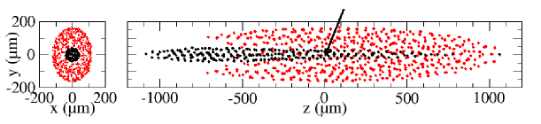
For the GBAR experiment, the idea [11] is to sympathetically cool a high velocity ion using a laser cooled trapped Be+ ion crystal. In a linear RF Paul trap, a laser cooled ion crystal in the Coulomb crystal regime has an ellipsoidal shape [16] as shown in Fig 1. The inter-ion distance is a few tens of microns and for ion numbers of a few thousand the crystal typically has dimensions of a few millimeters. We therefore have a low density mesoscopic system which would be poorly described by mean-field methods so we cannot use approximate methods [17] for the Coulomb interaction and we have to exactly compute it using the all-pairs approach.
We solve Newton’s equations including the time-dependent confinement electric fields of the linear trap, the exact Coulomb force between all ion pairs and the laser interaction [18, 19, 20, 21, 22, 23].
The confinement field derives from the potential [15]
| (1) |
including the radial confinement in the and directions. For this study, we use =0.1 V , =100 V, =3.5 mm and =2 13 MHz. The longitudinal confinement in the direction is described in terms of the axial oscillation frequency =2100 kHz for (which is smaller by a factor of and 3 for HD+ and 9Be+ respectively).
We describe the interaction with the cooling laser as a stochastic process of absorption (depending on the ion’s velocity through Doppler effect) spontaneous and stimulated emission, adding the corresponding velocity kicks to the laser cooled ions [24, 25]. The laser cooling beam is aligned with the trap axis. The waist of 1 mm is located at the trap center. The laser detuning is where =19 MHz is the natural width of the Be+ cooling transition and laser intensity is 1.5 times the saturation intensity.
The ion trajectories are computed using the velocity-Verlet algorithm [26] given by
| (2) |
where , , , is the force at time and is the integration time step.
3 Choice of the integration time step
To accurately describe the Radio Frequency trapping potential (RF) of the linear Paul trap the integration time step needs to verify
| (3) |
As we will show, the proper description of coulomb interactions between ions can lead to time steps orders of magnitude smaller than what Eq. (3) prescribes. Eq. (3) therefore gives an upper bound on the time step that can be used. We have checked that setting it to (about of the RF period) in our simulations, the trajectory of a single ion in the RF field is converged for simulations longer than 10 ms. The description of laser cooling in terms of random absorption and emission events imposes time steps much longer than the optical period, otherwise one would have to describe the laser interaction in terms of Bloch equations as discussed in [25]. For Be+ cooling at 313 nm, the optical period is 1 fs, so the time step can be adapted over several orders of magnitude.
3.1 Coulomb interaction simulations with a fixed time step
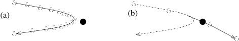
In Figure 2 we consider a Coulomb collision between two particles and illustrate that if the time step is too long, a Coulomb collision between two ions may be so poorly described that the two ions go through each other instead of repelling each other.
To understand the time step requirements of simulating the Coulomb interaction we simulated head-on 1D Coulomb collisions of two ions of equal masses and initially separated by 1 mm using a constant time step velocity-Verlet algorithm in the absence of the trapping field and the laser interaction. We send one ion at a given energy onto the other ion at rest. This problem has an analytical solution which predicts that the projectile ion transfers all its kinetic energy to the second ion.
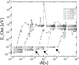
In Fig. 3 we show the energy of the projectile ion after the collision versus time step for different projectile energies. At a given projectile energy we can see that for a too long time step the ions don’t exchange much energy. However, there is a threshold time step below which we can reproduce the expected result of the projectile ion losing all its energy. Notice the intermediate regime where the time step is close to being small enough, the outgoing energy of the projectile ion can fluctuate quite wildly as the ions can come closer than their minimum approach distance, numerically adding energy to the system.
We can interpret the threshold time step by saying that in a time step the ions should move much less than their minimum approach distance. At the beginning of the collision most of the mechanical energy is in the kinetic energy of the projectile ion going at speed in the lab reference frame. The minimum approach distance is therefore given by
| (4) |
with , the charges of the two ions and the reduced mass. The displacement should obey leading to
| (5) |
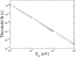
where we have obtained the right hand side of the equation by upper bounding the relative speed of the two ions by . We have fitted the threshold time steps found by such simulations to and have found excellent agreement, finding that should be approximately 4 times smaller than the right hand side of Eq. (5) for correct simulations. Figure 3 shows that the threshold time step is as small as for only of initial kinetic energy. This makes sympathetic cooling simulations of high temperature particles with a constant time step extremely demanding.
3.2 Variable time step criterion
Realistic dynamics of an ion crystal may involve fast ions and require very short time steps, e.g. if collisions with neutrals or exothermic reactions take place or as in the present case, if a fast ion is injected in a cold ion crystal to be sympathetically cooled. In this section, we show that a variable time step scheme allows us to have much longer time steps on average while accurately describing Coulomb interactions.
From the ideas of Sec. 3.1, we say that at every time step, for every ion pair, the relative change in distance should obey
| (6) |
with the distance between the two ions. We can reformulate the inequality in Eq. (6) as
| (7) |
with a constant to be chosen such that . For velocity-Verlet integration position updates are given by
| (8) |
therefore the displacement between two ions is upper bounded by
| (9) |
with and the relative velocity and acceleration. Inserting Eq. (9) in Eq. (7) and solving the second degree equation for one finds the following time step
| (10) |
Eq. (10) is specific to the case of a Velocity Verlet integration. Indeed, we have found that approximating by wasn’t sufficient to describe a Coulomb interaction because as the ions approach their minimal approach distance and as the velocity vanishes the second term in Eq. (9) can no longer be neglected.
The variable time step scheme is therefore to apply Eq. (10) to every ion pair and to update at every time step using
| (11) |
The all pairs computation of this variable time step scheme adds a lot of computation to the already expensive Coulomb evaluations because it involves three more square roots. Also, it requires more data transfers than the Coulomb force evaluations because it involves not only the particles’ positions, but also their speeds and accelerations. This variable time step scheme slows down the code by a factor of .
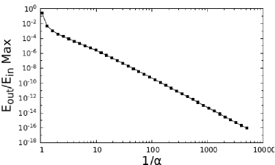
To verify this time step scheme, we simulated head-on 1D collisions of two ions with no trapping force nor laser cooling. We varied the parameter from down to . In Fig. 4 every point shows the maximum value of the ratio of the outgoing energy to the incoming energy of the projectile ion over 20000 simulations with collision energies in a geometric progression from to . For the time step is too long and the ratio is far from the analytically expected result of zero but as decreases, the ratio rapidly converges to zero. In Sec. 4, we use , which ensures an accurate description of the Coulomb collisions.
As a side note, one may elect to simulate at a constant time step such that Eq. (7) is valid for all ion pairs at all time steps. This may be achieved if the energy of any ion has an upper bound, known in advance, during the duration of a simulation. One could also upper bound relative velocities and accelerations to twice the maximum velocity and twice the maximum acceleration respectively, and lower bound the distance between two ions by the lowest distance found during the calculation of the Coulomb interaction. That way one could bring down the additional computational cost of the time step calculation to at the cost of smaller time steps.
4 sympathetic cooling
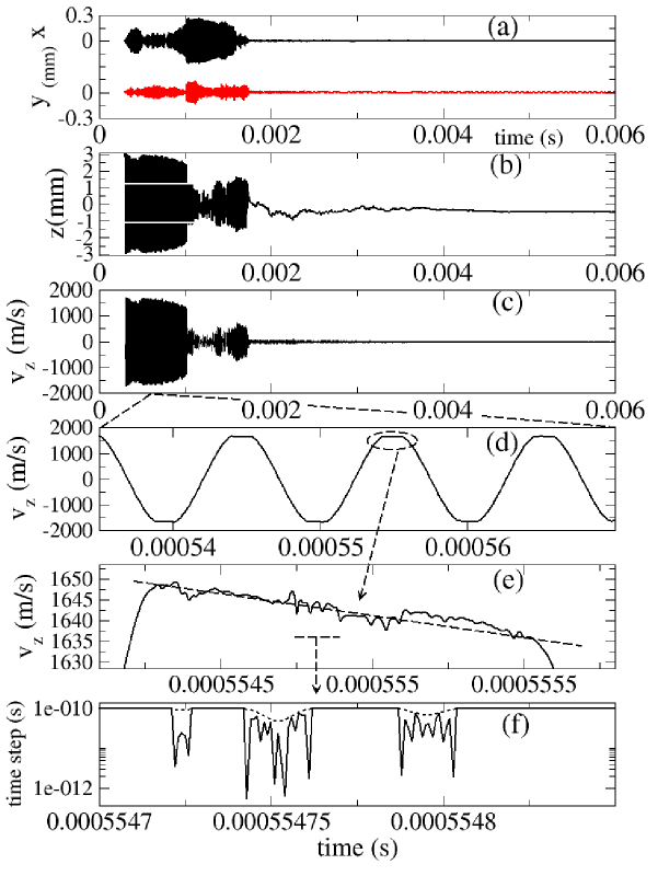
In this section, we study the capture and sympathetic cooling of an ion by a cloud of 500 laser cooled Be+ ions and 200 HD+ ions. The light HD+ ions undergo a tighter radial RF confinement and are located around the trap axis as in Fig. 1. The HD+ is sympathetically cooled by the 9Be+ and its purpose is to serve as an intermediary of more favorable mass ratio 3, compared to 9, for the sympathetic cooling of the . Indeed it is known from classical mechanics that optimal energy transfer in collisions occurs when the masses are equal. We have performed 5 simulations by varying the random number series used for ion position initialisation and laser interaction. All of them give very similar results and one is detailed in Fig. 5. The simulation first thermalises the 500 Be+ and 200 HD+ ions using laser cooling (not shown in Fig. 5) leading to the ion crystal shown in Fig.1. At 3 10-4 s, the projectile ion is added at rest close to the trap axis at and with a standard deviation corresponding to an initial potential energy of . Figure 5 shows that the projectile ion oscillates back and forth through the ion crystal for several ms before being captured and cooled. When the oscillation amplitude is large, the projectile ion spends most of its time out of the ion crystal where it isn’t cooled. Figure 5(d) shows that oscillates with a flat top behaviour corresponding to the Be+/HD+ crystal crossing. This is due to the fact that inside the ion crystal, the total electric field (trapping + Coulomb) is essentially zero such that the projectile ion does not feel any force. Figure 5(e) is a zoom on the flat top region. It shows that fluctuates due to collisions with the trapped Be+ or HD+ ions. The net effect of the crystal crossing is a slight decrease of the projectile axial velocity that results in projectile capture after many crossings.
Figure 5(f) shows a coarse grain view of the time step evolution with time. The solid and dashed lines correspond to the minimum and average time step over 50 ns time intervals. The minimum time step fluctuates due to Coulomb interactions within the crystal. One can see that when the projectile crosses the crystal, the time step is significantly reduced because the fast ion can come close to the Be+ or HD+ ions.
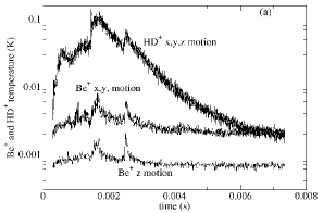
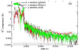
Figure 5(a) shows the trajectories of the projectile ion in the radial plane. Figure 6(a) shows the , and contributions to the mean macro-motion kinetic energy (expressed in Kelvin) of the Be+ and HD+ ions and Fig. 6(b) those of the projectile ion. One can see that the axial kinetic energy lost by the projectile ion when crossing the ion crystal is partly transferred into radial kinetic energy and also directly to the ion cloud explaining the spikes in the Be+ and HD+ temperatures. This energy is damped by the laser cooling process with a few ms scale leading to cooling of all projectile degrees of freedom and a stable behaviour. The projectile ion temperature slowly decays from more than 400 K in the z-direction down to the mK regime in less than 10 ms.
5 Conclusion
We have shown that simulating ionic interactions incurs a requirement on the time step to properly describe the Coulomb interaction. We have proposed and tested a variable time step scheme to accurately describe the Coulomb interaction while minimising the simulation time.
Using this scheme, we have performed accurate numerical simulations of sympathetic cooling of an ion by laser cooled Be+ and HD+ ions, showing that sympathetic cooling can be performed in less than 10 ms for a initial kinetic energy of 18.5 meV (more than 400 K). This result is very important to assess the feasibility of the Doppler sympathetic cooling step in the GBAR project. We will pursue these simulations to determine the dependence of the cooling time on the initial energy of the injected into the laser cooled crystal and on the size of the crystal. We also want to study sympathetic cooling of by a cloud as the improves cooling but is an extra experimental constraint.
6 Acknowledgements
This work was supported by the ANR-13-IS04-0002-01 BESCOOL grant and the COMIQ ITN. J.-Ph. Karr acknowledges Institut Universitaire de France.
References
- [1] J. C. J. Koelemeij, B. Roth, A. Wicht, I. Ernsting, and S. Schiller: Phys. Rev. Lett. 98 (2007) 173002.
- [2] J. Biesheuvel, J.-Ph. Karr, L. Hilico, K. S. E. Eikema, W. Ubachs, and J. C. J. Koelemeij: Nat. Commun. 7 (2016) 10385.
- [3] R. Blatt and C. Roos: Nat. Phys. 8 (2012) 277.
- [4] S.Willitsch: Int. Rev. Phys. Chem. 31 (2012) 175.
- [5] P. Eberle, A. D. Dörfler, C. von Planta, R. Krishnamurthy, D. Haas, D. Zhang, S. Y. T. van de Meerakker, and S. Willitsch: J. Phys. Conf. Ser. 635 (2015) 012012.
- [6] D. J. Wineland, R. E. Drullinger, and F. L. Walls: Phys. Rev. Lett. 40 (1978) 1639.
- [7] W. Neuhauser, M. Hohenstatt, P. Toschek, and H. Dehmelt: Phys. Rev. Lett. 41 (1978) 233.
- [8] L. Schmöger, O. O. Versolato, M. Schwarz, M. Kohnen, A. Windberger, B. Piest , S. Feuchtenbeiner, J. Pedregosa-Gutierrez, T. Leopold, P. Micke, A. K. Hansen, T. M. Baumann, M. Drewsen, J. Ullrich, P. O. Schmidt, J. R. Crespo López-Urrutia: Science 347 (2015) 1233.
- [9] P. Pérez et al. (GBAR collaboration): Hyperfine Interact. 233 (2015) 21.
- [10] P.Indelicato et al.(GBAR collaboration): Hyperfine Interact. 228 (2014) 141.
- [11] J. Walz and T. W. Hänsch: Gen. Rel. Gravit. 36 (2004) 561.
- [12] P. Pérez and Y. Sacquin: Class. Quantum Gravity 29 (2012) 18.
- [13] L. Schmöger, M. Schwarz, T. M. Baumann, O. Versolato, B. Piest, T. Pfeifer, J. Ullrich, P. O. Schmidt, and J. R. Crespo López-Urrutia: Rev. Sci. Instrum. 86 (2015) 103111.
- [14] M. Bussmann, U. Schramm, D. Habs, V. S. Kolhinen, and J. Szerypo: Int. J. Mass Spectrom. 251 (2006) 179.
- [15] L. Hilico, J.-Ph. Karr, A. Douillet, P. Indelicato, S. Wolf, and F. Schmidt Kaler: Int. J. Mod. Phys. Conf. Ser. 30 (2014) 1460269.
- [16] L. Turner: Phys. Fluids 30 (1987) 3196.
- [17] Parallel Computing : from Multicores and GPU’s to Petascale, eds. B. Chapman, F. Desprez, G. R. Joubert, A. Lichnewsky, F. Peters, and T. Priol, Advances in Parallel Computing Vol. 19 (IOS Press, Amsterdam, 2010).
- [18] C. B. Zhang, D. Offenberg, B. Roth, M. A. Wilson, and S. Schiller: Phys. Rev. A 76 (2007) 012719.
- [19] S. Schiller and C. Lämmerzahl: Phys. Rev. A 68 (2003) 053406.
- [20] K. Okada, M. Wada, T. Takayanagi, S. Ohtani, and H. A. Schuessler: Phys. Rev. A 81 (2010) 013420.
- [21] M. Marciante, C. Champenois, A. Calisti, J. Pedregosa-Guttierez, and M. Knoop: Phys. Rev. A. 82 (2010) 033406.
- [22] M. Marciante, C. Champenois, J. Pedregosa-Gutierrez, A. Calisti, and M. Knoop, Phys. Rev. A. 83 (2011) 021404.
- [23] M. Marciante, C. Champenois, A. Calisti, and M. Knoop: Appl. Phys. B. 107 (2012) 1117.
- [24] N. Sillitoe and L. Hilico, in Physics with charged trapped particles, eds. M. Knoop, N. Madsen, and R. C. Thompson, (World Scientific, London, 2016).
- [25] I. Rouse and S. Willitsch: Phys. Rev. A 92 (2015) 053420.
- [26] L. Verlet: Phys. Rev. 159 (1967) 98.