Multi-mode ultra-strong coupling in circuit quantum electrodynamics
With the introduction of superconducting circuits into the field of quantum optics Devoret and Schoelkopf (2013), many novel experimental demonstrations of the quantum physics of an artificial atom coupled to a single-mode light field have been realized Schuster et al. (2007); Kirchmair et al. (2013). Engineering such quantum systems offers the opportunity to explore extreme regimes of light-matter interaction that are inaccessible with natural systems. For instance the coupling strength can be increased until it is comparable with the atomic or mode frequency Yoshihara et al. (2016); Forn-Díaz et al. (2016); Casanova et al. (2010) and the atom can be coupled to multiple modes Sundaresan et al. (2015); McKay et al. (2015) which has always challenged our understanding of light-matter interaction Bethe (1947); Houck et al. (2008); Filipp et al. (2011); Gely et al. (2017); Malekakhlagh et al. (2017). Here, we experimentally realize the first Transmon qubit Koch et al. (2007) in the ultra-strong coupling regime, reaching coupling ratios of and we measure multi-mode interactions through a hybridization of the qubit up to the fifth mode of the resonator. This is enabled by a qubit with 88% of its capacitance formed by a vacuum-gap capacitance with the center conductor of a coplanar waveguide resonator. In addition to potential applications in quantum information technologies due to its small size and localization of electric fields in vacuum Cicak et al. (2010), this new architecture offers the potential to further explore the novel regime of multi-mode ultra-strong coupling.
Superconducting circuits such as microwave cavities and Josephson junction based artificial atoms Devoret and Schoelkopf (2013) have opened up a wealth of new experimental possibilities by enabling light-matter coupling that are orders of magnitude stronger than in analogue experiments with natural atoms Raimond et al. (2001) and by taking advantage of the versatility of engineered circuits. Experiments such as photon-number resolution Schuster et al. (2007) or Schrödinger-cat revivals Kirchmair et al. (2013) have beautifully displayed the quantum physics of a single-atom coupled to the electromagnetic field of a single mode. As the field matures, circuits of larger complexity are explored Forn-Díaz et al. (2016); Sundaresan et al. (2015); McKay et al. (2015), opening the prospect of controllably studying systems that are theoretically and numerically difficult to understand.
One example is the interaction between an (artificial) atom and an electromagnetic mode where the coupling rate becomes a considerable fraction to the atomic or mode eigen-frequency . This ultra-strong coupling (USC) regime, described by the quantum Rabi model, shows the breakdown of excitation number as conserved quantity, resulting in a significant theoretical challenge Casanova et al. (2010); Braak (2011). In the regime of , known as deep-strong coupling (DSC), a symmetry breaking of the vacuum is predictedGarziano et al. (2014) (i.e. qualitative change of the ground state), similar to the Higgs mechanism or Jahn-Teller instability. From a technological standpoint, the USC regime also has potential applications in quantum computation by decreasing gate times Romero et al. (2012) as well as the performance of quantum memories Stassi and Nori (2017). To date, such experiments have only been realized with flux qubits Yoshihara et al. (2016); Forn-Díaz et al. (2016) or in the context of digital quantum simulations Langford et al. (2016); Braumüller et al. (2016). With very strong coupling rates, the additional modes of an electromagnetic resonator become increasingly relevant, and U/DSC can only be understood in these systems if the multi-mode effects are correctly modeled. Previous extensions of the Rabi model have lead to un-physical predictions of dissipation rates Houck et al. (2008) or the Lamb shift Gely et al. (2017) arising from a multi-mode interaction. Recently, new models have been developed in which these unphysical predictions no longer arise Gely et al. (2017); Malekakhlagh et al. (2017). However, experiments have yet to reach a parameter regime where such physics becomes relevant.
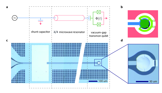
Here, we realize a superconducting quantum circuit with a Transmon qubit Koch et al. (2007) in the multi-mode USC regime where past extensions standard quantum Rabi models have failed. The qubit consists of a superconducting island shorted to ground by two Josephson junctions in parallel (or SQUID), which is suspended above the voltage anti-node of a quarter wavelength () coplanar waveguide microwave cavity as shown in Figs. 1(a,b). This vacuum-gap Transmon architecture offers various possibilities that could prove technologically useful; its an order of magnitude smaller (m in diameter) than normal Transmon qubits, its fields are predominantly in vacuum potentially enabling higher coherence Cicak et al. (2010), and it offers the possibility to couple in-situ to the mechanical motion of the suspended island by applying a voltage bias to the center conductor Pirkkalainen et al. (2013). In this study we use this architecture to maximize the coupling. Indeed, the coupling rate is proportional to the capacitance ratio between the qubit capacitance to the resonator and the total qubit capacitance , . In this architecture, the vacuum-gap capacitance dominates, leading to . Note that by changing the position of the Transmon along the resonator or its capacitance ratios, its coupling can be reduced to standard coupling rates for other applications.
Multi-mode effects play a key role in the physics of this system, but we will start by considering the more simple case of the fundamental mode of the resonator interacting with the Transmon (with levels of increasing energy). This is described using an extension of the quantum Rabi Hamiltonian Koch et al. (2007)
| (1) |
Here () is the annihilation operator for the resonator (Transmon) excitations, with frequency () and is the reduced Planck constant. The third term introduces the weak anharmonicity of the Transmon, quantified by the charging energy and the last term describes the coupling of the Transmon to the resonator. Changing the magnetic flux through the SQUID loop of the Transmon allows us to vary the Josephson energy and hence the frequency and the coupling Koch et al. (2007)
| (2) |
with the voltage zero point fluctuations of the microwave cavity and the electron charge. In our system, USC is due to , whereas in usual planar geometries. For a Transmon qubit coupled to a single mode, a natural limit on the coupling rate is given by Bosman et al. (2017)
| (3) |
The light-matter interaction has two types of contributions. The first terms conserve excitations, and remain after applying the rotating-wave approximation (RWA). The second terms, called counter-rotating terms, add and extract excitations from the qubit and resonator in a pair-wise fashion. For sufficiently small couplings the non-RWA terms can be neglected reducing the Rabi model to the Jaynes-Cummings model Jaynes and Cummings (1963). For higher couplings the RWA is no longer applicable and the excitation number conservation of the JC model is replaced by a conservation of excitation number parity Braak (2011). In this regime, making the RWA would lead to a deviation in the energy spectrum of the system known as Bloch-Siegert shift , marking the entry into the USC regime Forn-Díaz et al. (2010).
Our samples, depicted in Fig. 1(c,d), are fabricated on a sapphire substrate and use as superconductor an alloy of molybdenum-rhenium (MoRe) Singh et al. (2014). In a five step electron beam lithography process we pattern the microwave resonator, shunt capacitor dielectric, vacuum-gap sacrificial layer and lift-off mask for the MoRe suspension (see methods for more details). In the last step we pattern and deposit the Josephson junctions using aluminum shadow evaporation and perform the release of the vacuum-gap capacitor and aluminum lift-off in the same step. In this study we spectroscopically characterize two devices A and B, with vacuum-gap sizes of 155 nm (A) and 350 nm (B).
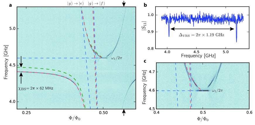
Fig. 2 shows the spectral response of device A using single-tone microwave reflectometry at 14 mK. By measuring the complex scattering parameter of the circuit as a function of an external magnetic field, we can probe the absorption of the circuit at a given frequency within the circulator and amplifier bandwidth of 4-8 GHz (see SISI for full experimental setup). The transitions of the circuit appear as a dip in the magnitude of the scattering parameter, , thereby mapping the spectrum of the circuit. From the avoided crossing, depicted in Fig. 2(a,b), we determine the vacuum Rabi splitting (VRS) to be GHz. This provides an estimate of the coupling through the relation . We obtain a ratio indicating we are in the USC regime.
Fig. 2(c) shows a detailed zoom of the observed spectrum close to half a flux quantum (). In this regime, becomes small, such that the qubit frequency goes towards zero for very symmetric junctions, and negligible loop inductance, and the Transmon becomes more like a Cooper-pair box (CPB) as the ratio of drops Koch et al. (2007). Note that in this regime the physics of the qubit can no longer be described by the Duffing oscillator of Eq. 1, but rather by the CPB Hamiltonian as was used in all fits of the data Gely et al. (2017). In this flux region, we observe two notable features. The first is an anti-crossing at , which we attribute to an avoided crossing with the to transition of the qubit (indicated with the blue dashed line on the right). This shows that in this flux region the qubit behaves like a CPB as such transitions are exponentially suppressed in the Transmon regime Koch et al. (2007). The second feature is a jump of the dressed cavity to the frequency of the bare cavity at . Such jumps to the bare cavity frequency have been observed before as quantum to classical transitions by applying either high powers of a coherent drive or white noise to the cavity Bishop et al. (2010); Fink et al. (2010). In our experiment the critical power of the drive tone that determines the onset of this quasi-harmonic regime is strongly dependent on the flux-bias point. For driving powers corresponding to less than intra-cavity photons, the bar-like feature becomes power independent, measured with drive powers as low as , ruling out a role of the applied drive tone in this feature. We attribute this quenching of the light-matter interaction to a thermal excitation of the low frequency qubit by the environment. We believe that the transition is observable in our experiment due to a combination of very symmetric junctions in device A, resulting in qubit frequencies that can be excited by the thermal bath of the dilution refrigerator, together with the USC regime that still significantly dresses the cavity resonance even for such large detunings.
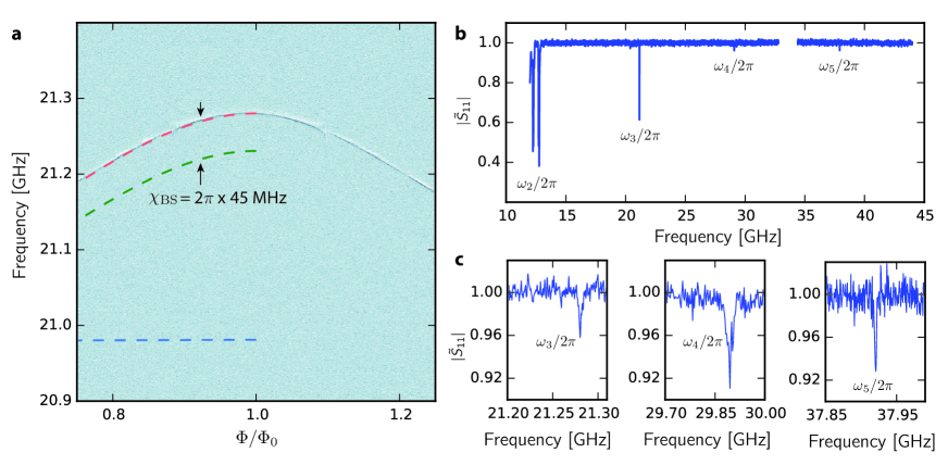
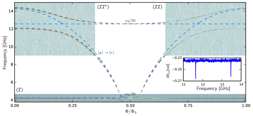
Fig. 3 depicts the spectrum of device B over the full flux periodicity (for device A see SI SI ). It is a composition of a single tone measurement, as in Fig. 2, combined with a two-tone spectroscopy measurement Wallraff et al. (2004). In such a measurement the change in cavity response is probed using a weak probe tone as a function of a second drive tone at the qubit. Due to the qubit-state dependent dispersive shift of the cavity at , the reflection of the weak probe tone changes as the drive tone excites the qubit. We observe an avoided crossing of the qubit with the fundamental mode ( GHz) and the second mode , and the frequency maximum of the qubit of GHz. From the avoided crossing of the qubit with the second mode we obtain a splitting of GHz, as shown in the inset. We observe that these two splittings follow the relation , thereby we observe that the scaling of the VRS evolves linearly with mode number Filipp et al. (2011). Due to a resolved Bloch-Siegert shift (explained below), we conclude that this device is in the USC regime, wherein the higher modes of the resonator cannot be neglected.
From the observations of USC to multiple modes in our experiment, it is clear that a quantitative analysis of our experiment should be based on a model that includes multiple modes of the cavity. Typically this has been done by extending the Rabi model (Eq. 1) through a square-root increase in coupling strength with mode number . However, as is well established in the literature, such straightforward extensions of the JC and Rabi model to multi-mode systems suffer from divergence problems Houck et al. (2008); Filipp et al. (2011). In particular, there is a problem with the predicted qubit frequency due to a divergence of the Lamb shift when the dispersive shift from all of the modes is included Gely et al. (2017). In previous experiments where the coupling is small, and the size of the qubit compared to the cavity wave-length is large, a natural cut-off in the number of modes seems to solve these issues and does not reveal the full extent of divergence problems in extended Rabi models Filipp et al. (2011). In our case, the small size of our qubit and the USC regime yield a unphysical GHz Lamb shift of the qubit following this methodology. Another cut-off associated with the non-zero capacitance of the qubit to ground Gely et al. (2017) leads to a similar shift. This issue can be overcome by using black-box circuit quantization Nigg et al. (2012), but with this method we would lose the strict separation of atomic and photonic degrees of freedom typical of the Rabi model, which is essential to estimating the role of counter-rotating terms in the systems spectrum. Additionally, the analysis is then limited to the weakly anharmonic regime of the Transmon qubit whilst our system also enters the Cooper-pair box regime (see Fig. 2(c)).
Overcoming this issue led to recent theoretical work Gely et al. (2017), where a first-principle quantum circuit model was developed based on a lumped element equivalent of this Transmon architecture. This model circumvents the divergence problems of conventional extensions of the Hamiltonian. The red dashed lines in Figs. 2 and 3 show a fit of our observed spectrum to the model, demonstrating excellent agreement SI . The fits from the circuit model also allow the extraction of the bare cavity and qubit lines, shown by the blue dashed lines. Note that the definition of the bare qubit frequency strongly differs from typical definitions Koch et al. (2007) since it increases (is renormalized) with the number of modes considered in the model. This renormalization is a consequence of the physics of our circuit and compensates the Lamb shift of higher modes. It notably leads to the vacuum Rabi splittings not being symmetrical with respect to the point at which bare qubit and mode cross in Figs. 2 and 3. An additional feature of the quantum circuit model is that we are able to quantify the relevance of the counter-rotating terms of the interaction between the qubit and the resonator modes. To do this, we perform the same calculation but removed the counter-rotating terms from the Hamiltonian of the model. The result is shown by the dashed green lines and allows us to unambiguously extract the resulting vacuum Bloch-Siegert shift , characteristic of the USC regime Forn-Díaz et al. (2010). For device A for example, we find a shift of MHz (see Fig. 2), which is about 20 times the cavity line-width, clearly demonstrating our experiment is in the USC regime. Finally we can extract the magnitude of the coupling at its maximum () and obtain for device A a value of MHz, resulting in a coupling ratio of
By examining the composition of the eigenstates obtained from our model, we expect that the qubit should be strongly hybridized with multiple modes of the cavity. In Fig. 4, we show measurements demonstrating this hybridization. Using two tone spectroscopy as in Fig. 3, we are able to observe the higher-modes, by monitoring the response of the hybridized fundamental mode while driving the higher modes. Fig. 4(a) shows a measurement of the third mode of the cavity as a function of flux. Due to the strong hybridization, we observe a flux tuning of 70 MHz despite a detuning from the qubit by 7 GHz. The red dashed line shows the expected dressed state of as predicted from our model, which is in agreement with the data. The bare frequency of this mode is 20.98 GHz indicated with the blue dashed line, from which we extract a dispersive shift of 200 - 270 MHz. Furthermore from the model we find that the counter-rotating terms are crucial for this physics, as the predicted spectrum shifts more than 50 MHz by removing them from the Hamiltonian, as indicated with the green dashed line.
Fig. 4(b) shows such a measurement up to 45 GHz. In addition to the third mode shown in Fig. 4(a), we also observe the fourth and the fifth mode of the cavity, demonstrating the qubit induced hybridization over five modes of the cavity extended up to 38 GHz.
To conclude, we have introduced a novel circuit architecture based on the Transmon qubitKoch et al. (2007), where a vacuum-gap capacitor significantly dominates the total capacitance of the qubit.
Being ten times smaller than existing Transmon architectures, together with the prospect of higher possible coherence by localizing electric fields in vacuum, this new device could have potential applications in quantum computing technologies.
Here, we have used this new architecture to maximize the coupling between the qubit and the microwave resonator by increasing the capacitance participation ratio to .
Doing so, we realized couplings with the fundamental mode up to MHz, well within the USC limit, and found that the multi-mode character of the resonator plays a crucial role in the physics of the circuit.
Using a quantum circuit model, we found a Bloch-Siegert shift induced by counter-rotating terms of up to MHz.
Combining this architecture with high-impedance microwave resonators Samkharadze et al. (2016); Bosman et al. (2017) and a smaller free spectral range Sundaresan et al. (2015), we expect to reach even further into the multi-mode ultra-strong coupling regime to probe exotic states of light and matter Andersen and Blais (2016).
Methods
Fabrication
In the first step, we define the bottom metalization layer of the cavity, including the bottom layers of the shunt-capacitor and the vacuum-gap capacitor, on top of a sapphire substrate. We use magnetron sputtering to deposit a nm thick layer of molybdenum-rhenium (MoRe) alloy and pattern it by means of electron-beam lithography (EBL) and SF6/He reactive ion etching (RIE). For the definition of the shunt-capacitor dielectric, we deposit a nm thick layer of silicon nitride by means of plasma-enhanced chemical vapor deposition and perform the patterning by EBL and wet etching in buffered hydrofluoric acid. In a third EBL step we pattern the sacrificial layer for the vacuum-gap capacitor, which in our samples consists of a nm thick layer of the electron-beam resist PMGI SF7 diluted with cyclopentanone. After the development of the sacrificial layer in L-ethyl-lactate, stopped by rinsing with isopropanol, we reflow the patterned PMGI for s at ∘C in order to slightly smooth the stepped edge, facilitating the sidewall metalization in the next step. The shunt-capacitor and vacuum-gap capacitor top electrodes are fabricated subsequently by means of lift-off technique. First, we perform EBL to pattern the corresponding PMMA resist layer and secondly, we sputter deposit a nm thick layer of MoRe on top. We do the lift-off in hot xylene, while the sacrificial layer of the vacuum-gap capacitor is not attacked in this process and thus remains unchanged. In the last step, we fabricate the Josephson junctions using a PMGI/PMMA bilayer lift-off mask, EBL and aluminum shadow-evaporation. Finally, we perform a simultaneous Al lift-off and the drum release in the resist stripper PRS3000 and dry the sample by means of critical point drying.
Data visualization For the color plots of Figs. 2,3 and 4, we applied an image processing filter using Spyview, which histogrammically subtracts the mean of each line of constant frequency with outlier rejection, 90% low, 2% high to remove flux-independent features such as cable resonances.
Author Contributions S. J. B. and G. A. S. conceived the experiment. S. J. B. designed and fabricated the devices. V. S. , A. B. and G. A. S. provided input for the fabrication. S. J. B. and M. F. G. did the measurements with input of D. B. and G. A. S.. M. F. G. and D. B. performed data analysis with input of S. J. B. and G. A. S.. Manuscript was written by S. J. B., M. F. G. and G. A. S., and all authors provided comments to the manuscript. G. A. S. supervised the work.
Acknowledgments We wish to acknowledge Enrique Solano, Adrian Parra-Rodriguez and Enrique Rico Ortega for valuable input and discussions.
References
- Devoret and Schoelkopf (2013) M. H. Devoret and R. J. Schoelkopf, Science 339, 1169 (2013).
- Schuster et al. (2007) D. I. Schuster, A. A. Houck, J. A. Schreier, A. Wallraff, J. M. Gambetta, A. Blais, L. Frunzio, J. Majer, B. Johnson, M. H. Devoret, S. M. Girvin, and R. J. Schoelkopf, Nature 445, 515 (2007).
- Kirchmair et al. (2013) G. Kirchmair, B. Vlastakis, Z. Leghtas, S. E. Nigg, H. Paik, E. Ginossar, M. Mirrahimi, L. Frunzio, S. M. Girvin, and R. J. Schoelkopf, Nature 495, 205 (2013).
- Yoshihara et al. (2016) F. Yoshihara, T. Fuse, S. Ashhab, K. Kakuyanagi, S. Saito, and K. Semba, Nature Physics 13, 44 (2016).
- Forn-Díaz et al. (2016) P. Forn-Díaz, J. J. García-Ripoll, B. Peropadre, J.-L. Orgiazzi, M. A. Yurtalan, R. Belyansky, C. M. Wilson, and A. Lupascu, Nature Phys. 13, 39 (2016).
- Casanova et al. (2010) J. Casanova, G. Romero, I. Lizuain, J. J. García-Ripoll, and E. Solano, Phys. Rev. Lett. 105, 263603 (2010).
- Sundaresan et al. (2015) N. M. Sundaresan, Y. Liu, D. Sadri, L. J. Szőcs, D. L. Underwood, M. Malekakhlagh, H. E. Türeci, and A. A. Houck, Phys. Rev. X 5, 021035 (2015).
- McKay et al. (2015) D. C. McKay, R. Naik, P. Reinhold, L. S. Bishop, and D. I. Schuster, Phys. Rev. Lett. 114, 080501 (2015).
- Bethe (1947) H. A. Bethe, Phys. Rev. Lett. 72, 339 (1947).
- Houck et al. (2008) A. A. Houck, J. A. Schreier, B. R. Johnson, J. M. Chow, J. Koch, J. M. Gambetta, D. I. Schuster, L. Frunzio, M. H. Devoret, S. M. Girvin, and R. J. Schoelkopf, Phys. Rev. Lett. 101, 080502 (2008).
- Filipp et al. (2011) S. Filipp, M. Göppl, J. M. Fink, M. Baur, R. Bianchetti, L. Steffen, and A. Wallraff, Phys. Rev. A 83, 063827 (2011).
- Gely et al. (2017) M. F. Gely, A. Parra-Rodriguez, D. Bothner, Y. M. Blanter, S. J. Bosman, E. Solano, and G. A. Steele, arXiv:1701.05095 (2017).
- Malekakhlagh et al. (2017) M. Malekakhlagh, A. Petrescu, and H. E. Türeci, arXiv:1701.07935v2 (2017).
- Koch et al. (2007) J. Koch, T. M. Yu, J. Gambetta, A. A. Houck, D. I. Schuster, J. Majer, A. Blais, M. H. Devoret, S. M. Girvin, and R. J. Schoelkopf, Phys. Rev. A 76, 042319 (2007).
- Cicak et al. (2010) K. Cicak, D. Li, J. A. Strong, M. S. Allman, F. Altomare, A. J. Sirois, J. D. Whittaker, J. D. Teufel, and R. W. Simmonds, Appl. Phys. Lett. 96, 093502 (2010).
- Raimond et al. (2001) J.-M. Raimond, M. Brune, and S. Haroche, Rev. Mod. Phys. 73, 565 (2001).
- Braak (2011) D. Braak, Phys. Rev. Lett. 107, 100401 (2011).
- Garziano et al. (2014) L. Garziano, R. Stassi, A. Ridolfo, O. Di Stefano, and S. Savasta, Phys. Rev. A 90, 043817 (2014).
- Romero et al. (2012) G. Romero, D. Ballester, Y. M. Wang, V. Scarani, and E. Solano, Phys. Rev. Lett. 108, 120501 (2012).
- Stassi and Nori (2017) R. Stassi and F. Nori, arXiv:1703.08951 (2017).
- Langford et al. (2016) N. K. Langford, R. Sagastizabal, M. Kounalakis, C. Dickel, A. Bruno, F. Luthi, D. J. Thoen, A. Endo, and L. DiCarlo, arXiv:1610.10065 (2016).
- Braumüller et al. (2016) J. Braumüller, M. Marthaler, A. Schneider, A. Stehli, H. Rotzinger, M. Weides, and A. V. Ustinov, arXiv:1611.08404 (2016).
- Nigg et al. (2012) S. E. Nigg, H. Paik, B. Vlastakis, G. Kirchmair, S. Shankar, L. Frunzio, M. H. Devoret, R. J. Schoelkopf, and S. M. Girvin, Phys. Rev. Lett. 108, 240502 (2012).
- Bosman et al. (2015) S. J. Bosman, V. Singh, A. Bruno, and G. A. Steele, Appl. Phys. Lett. 107, 192602 (2015).
- Pirkkalainen et al. (2013) J.-M. Pirkkalainen, S. Cho, J. Li, G. Paraoanu, P. Hakonen, and M. Sillanpää, Nature 494, 211 (2013).
- (26) See supplementary material.
- Bosman et al. (2017) S. J. Bosman, M. F. Gely, V. Singh, D. Bothner, A. Castellanos-Gomez, and G. A. Steele, arXiv:1704.04421 (2017), arXiv:1704.04421 .
- Jaynes and Cummings (1963) E. T. Jaynes and F. W. Cummings, Proceedings of the IEEE 51, 89 (1963), 04773.
- Forn-Díaz et al. (2010) P. Forn-Díaz, J. Lisenfeld, D. Marcos, J. J. García-Ripoll, E. Solano, C. J. P. M. Harmans, and J. E. Mooij, Phys. Rev. Lett. 105, 237001 (2010).
- Singh et al. (2014) V. Singh, B. H. Schneider, S. J. Bosman, E. P. J. Merkx, and G. A. Steele, Appl. Phys. Lett. 105, 222601 (2014).
- Bishop et al. (2010) L. S. Bishop, E. Ginossar, and S. M. Girvin, Phys. Rev. Lett. 105, 100505 (2010).
- Fink et al. (2010) J. M. Fink, L. Steffen, P. Studer, L. S. Bishop, M. Baur, R. Bianchetti, D. Bozyigit, C. Lang, S. Filipp, P. J. Leek, and A. Wallraff, Phys. Rev. Lett. 105, 163601 (2010).
- Wallraff et al. (2004) A. Wallraff, D. I. Schuster, A. Blais, L. Frunzio, R.-S. Huang, J. Majer, S. Kumar, S. M. Girvin, and R. J. Schoelkopf, Nature 431, 162 (2004).
- Samkharadze et al. (2016) N. Samkharadze, A. Bruno, P. Scarlino, G. Zheng, D. P. DiVincenzo, L. DiCarlo, and L. M. K. Vandersypen, Phys. Rev. Applied 5, 044004 (2016).
- Andersen and Blais (2016) C. K. Andersen and A. Blais, arXiv preprint arXiv:1607.03770 (2016).