Magnetic skyrmions and skyrmion clusters in the helical phase of Cu2OSeO3
Abstract
Skyrmions are nanometric spin whirls that can be stabilized in magnets lacking inversion symmetry. The properties of isolated skyrmions embedded in a ferromagnetic background have been intensively studied. We show that single skyrmions and clusters of skyrmions can also form in the helical phase and investigate theoretically their energetics and dynamics. The helical background provides natural one-dimensional channels along which a skyrmion can move rapidly. In contrast to skyrmions in ferromagnets, the skymion-skyrmion interaction has a strong attractive component and thus skyrmions tend to form clusters with characteristic shapes. These clusters are directly observed in transmission electron microscopy measurements in thin films of Cu2OSeO3. Topological quantization, high mobility and the confinement of skyrmions in channels provided by the helical background may be useful for future spintronics devices.
In crystals lacking inversion symmetry, subtle relativistic interactions lead to the formation of exotic spin textures Dzyaloshinskii (1964); Bogdanov and Yablonskii (1989); Bogdanov and Hubert (1994); Janson et al. (2014). For example, in chiral magnets such as Cu2OSeO3, ferrimagnetically ordered spins spontaneously cant to form helices with a pitch of nm Adams et al. (2012); Seki et al. (2012a); Rajeswari et al. (2015). Upon applying a tiny magnetic field, lattices of stable magnetic whirls emerge Seki et al. (2012a, b); Nagaosa and Tokura (2013); Langner et al. (2014); Zhang et al. (2016a, b, c). Due to the nanometer confinement and sensitivity to electromagnetic control, these magnetic structures have potential for new spintronic devices.
In particular, the spin direction of a magnetic skyrmion wraps once around the unit sphere. This implies that the spin configuration cannot be continuously deformed to another magnetic state i.e, skyrmions are topologically protected particles Nagaosa and Tokura (2013); Mühlbauer et al. (2009). Therefore they can be created and destroyed only by singular magnetic configurations Milde et al. (2013). Furthermore, for sufficiently small temperatures and magnetic fields, skyrmions can have practically an infinite lifetime Hagemeister J. et al. (2015). As a very smooth magnetic configuration, skyrmions couple only weakly to local defects Müller and Rosch (2015); Iwasaki et al. (2013a). Instead, they couple extremely well to external forces. In metals and heterostructures, skyrmions can be manipulated by small electric or thermal currents Iwasaki et al. (2013a); Jonietz et al. (2010); Yu et al. (2012); Lin et al. (2014) while in magnetoelectric insulators they can be manipulated dissipationlessly with electric fields Seki et al. (2012c); White et al. (2012, 2014); Omrani et al. (2014), heat currents Lin et al. (2014); Koshibae and Nagaosa (2014), and laser pulses Ogawa et al. (2015); Berruto and Carbone (2017). Furthermore, skyrmions are repelled from the edges of nanostructures and react very fast to external control Sampaio et al. (2013); Woo et al. (2016); Zhang et al. (2015, 2017).
From the application perspective, research has mainly focused on the manipulation of skyrmions in a ferromagnetic background. For example, it has been suggested to build memory devices Fert et al. (2013) based on skyrmions arranged in a nanowire where information is encoded in the distance between skyrmions. Alternative designs use nanostructures with lanes for skyrmions where the information is stored in the lane number Müller (2017).
An interesting alternative is to consider skyrmions in a helical background. This problem, first studied by Ezawa Ezawa (2011), has, up to now, received little attention. Such states naturally occur when the phase transition from the skyrmion crystal phase to the helical phase is investigated Milde et al. (2013); Schütte and Rosch (2014). We argue that four major properties distinguish skyrmions in a helical background from their cousins in a ferromagnetic environment: (i) Skyrmions naturally move along the tracks defined by the helical order. Currents perpendicular to these naturally formed tracks are expected to drive skyrmions to very high speeds especially in materials with low Gilbert damping Iwasaki et al. (2013a, b); Sampaio et al. (2013). (ii) In the helical phase, skyrmions are metastable even for vanishing magnetic field. In contrast, skyrmions in the ferromagnetic state require either a sufficiently strong external magnetic field or sufficiently strong easy-axis anisotropy to guarantee local stablility Ezawa (2011); Müller et al. (2016); Kézsmárki et al. (2015). (iii) While in the ferromagnetic state only one type of skyrmion is preferred by the background magnetization Koshibae and Nagaosa (2016), in the helical phase skyrmions and antiskyrmions can coexist moving on different tracks in the helical background. (iv) While the skyrmion-skyrmion interaction is typically repulsive in the ferromagnetic case Bogdanov (1995); Zhang et al. (2015), there are strong attractive components in the helical phase which naturally lead to the formation of skyrmion dimers and larger skyrmion clusters. Recently, clusters of skyrmions were also predicted Leonov et al. (2016a) in a conical background. Leonov et al. Leonov et al. (2016b) studied experimentally the hysteretic behavior in this regime and the formation of multidomain patterns. After submission of this manuscript, a study by Loudon et al. Loudon et al. (2017) reported the observation of skyrmion clusters within the conical phase. Other works suggest attractive skyrmions in a fully polarized background only if an additional frustrated exchange Rózsa et al. (2016) is taken into account. Also clusters in a homogeneous background have been measured under strong geometrical confinement Zhao et al. (2016). In a helical background, however, the attractive interaction intrinsically arises from the helical modulations and thus no additional extensions of the minimal model are required.
In the following, we will first describe the theory of skyrmions in the helical phase, their interactions, and the formation of clusters of skyrmions. Energies and magnetic fields will be measured in units of and , respectively. These are set by the exchange coupling and the critical field stabilizing the ferromagnet, see the Supplemental Material sup . To observe these clusters experimentally, we acquired real space and real time movies of the helical-skyrmion phase transition in a thin film of Cu2OSeO3 using Lorentz transmission electron microscopy (LTEM) sup . The movies reveal the nucleation of skyrmions in the helical background and their tendency to arrange in clusters of different configurations.
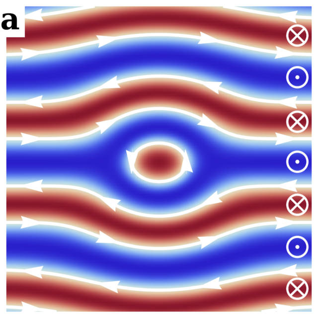
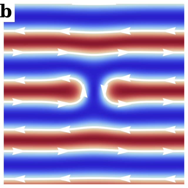
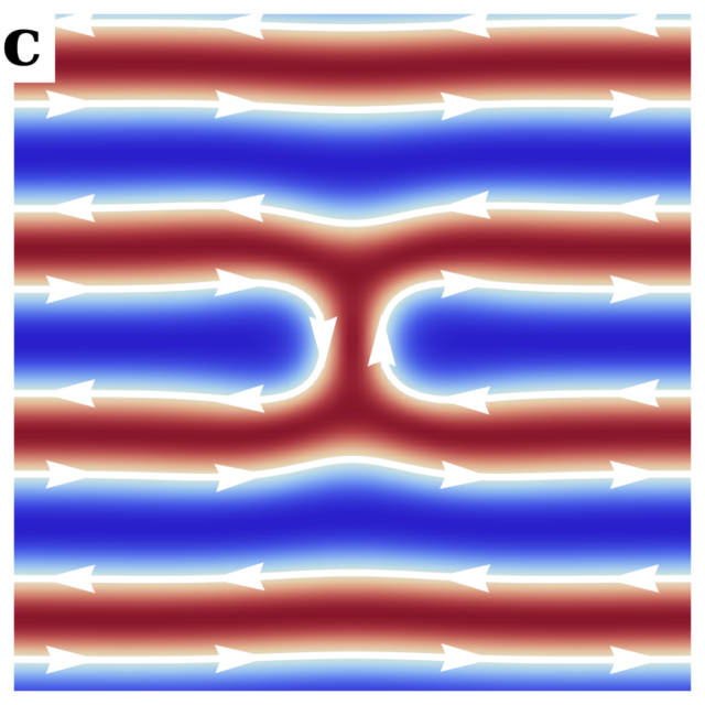
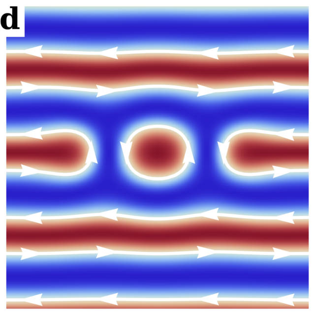
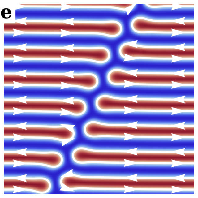
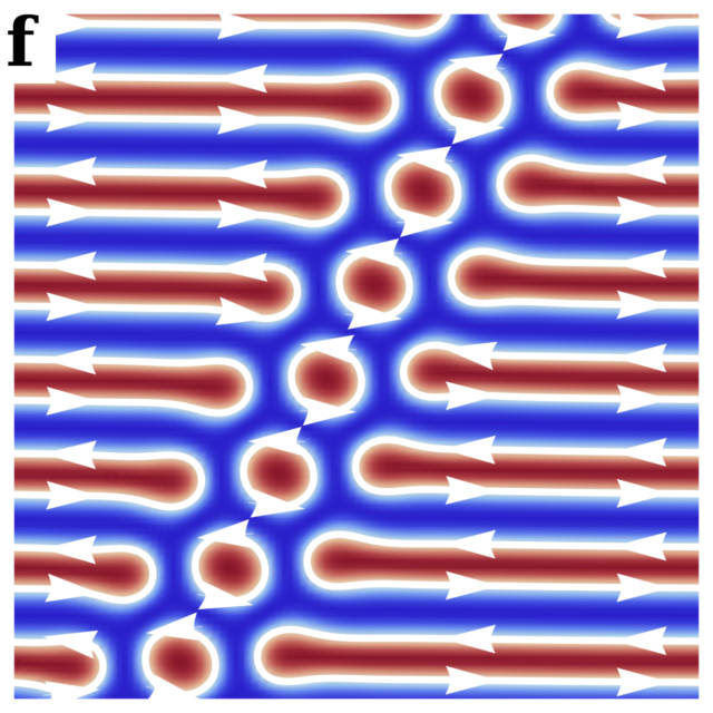
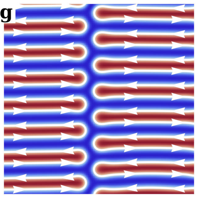
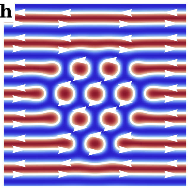
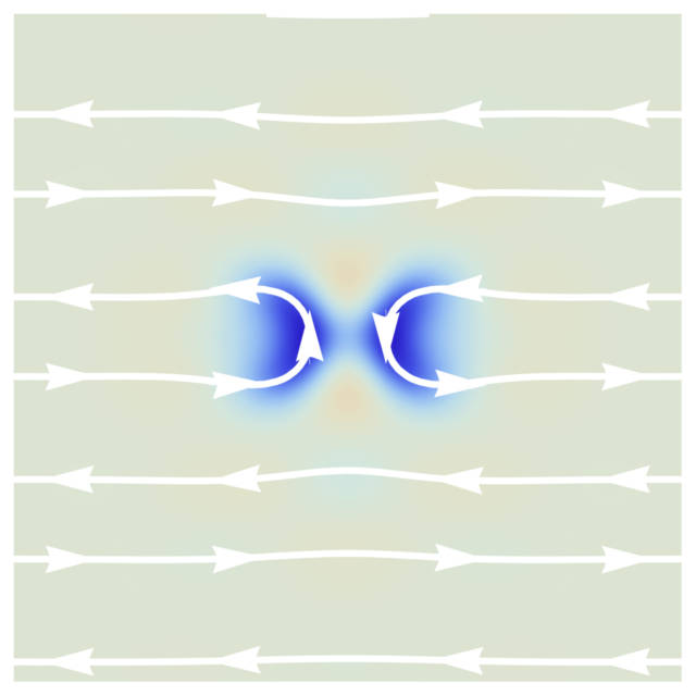
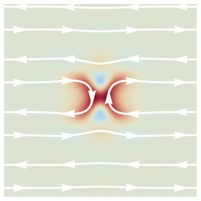
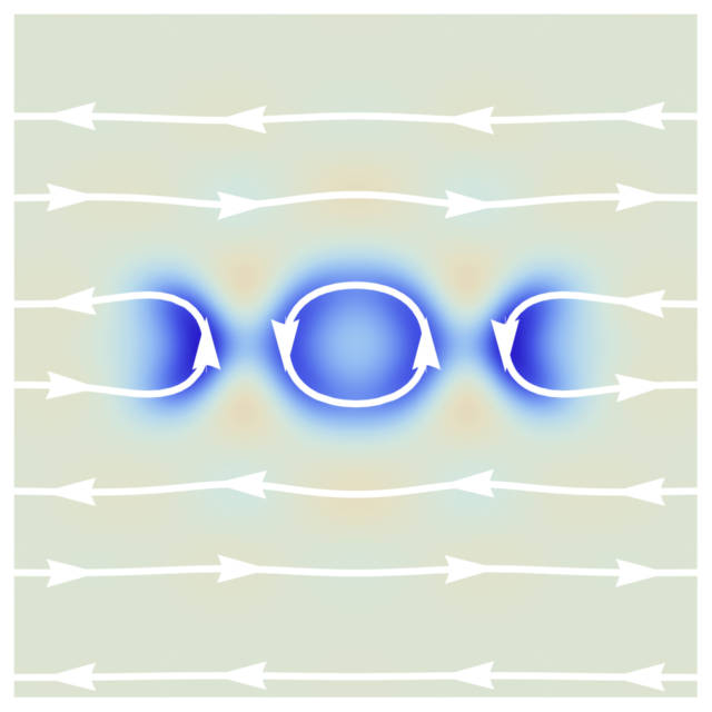
Single skyrmions in a helical phase: To investigate the energetics of skyrmions in a helical background, we performed micromagnetic simulations, see Supplemental Material sup . Figure S1 depicts the different skyrmion configurations: top panels represent single skyrmions and the characteristic skyrmion dimer. Bottom panels show the different multiskyrmion cluster configurations. While the “interstitial” skyrmion in panel (a) resembles the well-known skyrmion in a ferromagnetic background, the H-shaped skyrmion of panel (b) can be viewed as a bound state of two half-skyrmions (merons) defined by the ends of a helical strip, also refered to as a meron pair in Ref. 35. An antiskyrmion (panel (c)) with opposite winding number can be obtained by time reversal. Panel (d) represents the formation of a two-skyrmion dimer bound state due to the presence of attractive interactions. Plots of the winding number densities show that the skyrmions are indeed well localized, see Supplemental Material sup .
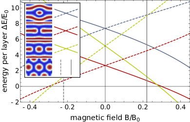
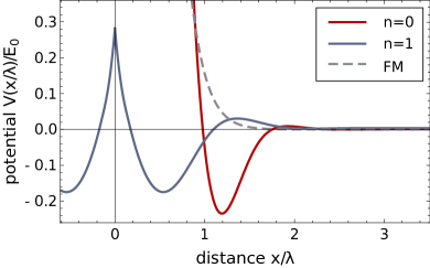
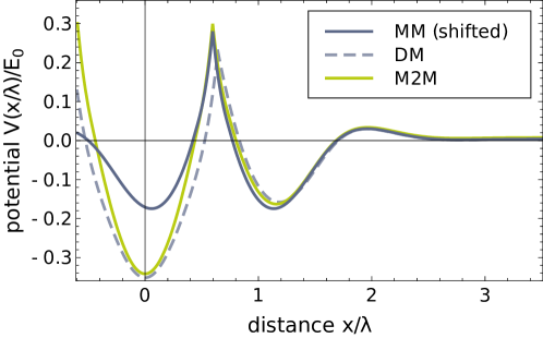
Figure 2(a) shows the energetics of four configurations of skyrmions (solid lines) and the corresponding antiskyrmions (dashed lines). Blue and red lines represent the energetics of the “interstitial” and the H-shaped configuration, respectively, and the green lines describe the dimer state. The H-shaped state requires much less distortion of the helical background lattice and has a significantly lower energy than the interstitial state. However, both states have the same winding number Ezawa (2011); sup and can be smoothly deformed into each other. For , skyrmions and antiskyrmions are degenerate but since each skyrmion configuration carries a finite magnetization, they split linearly in the magnetic field. Above a critical field the energy of a single skyrmion becomes negative with respect to the pure helical background implying that above this field the system energetically favors the proliferation of skyrmions. The exact critical field for the phase transition to the skyrmion lattice is, however, slightly lower due to attractive interactions between skyrmions (explained below).
By translational symmetry it costs no energy for a single skyrmion to move parallel to the track defined by the helical background. In contrast, a huge energy barrier of several exchange coupling constants (per layer of the material) prohibits the motion to the parallel lane as can be estimated from the large energy value of the interstitial skyrmion configuration. This confinement has also important consequences for the velocity of the skyrmion when it is driven by a spin-current perpendicular to the confining walls where we assume that the helix is pinned by disorder. In a ferromagnet, the skyrmion would flow in the direction of the spin current with a velocity of the order of , the velocity characterizing the spin current Thiele (1973). Instead, the helical background acts as a confining potential Iwasaki et al. (2013a, b); Sampaio et al. (2013); Müller (2017); Müller and Rosch (2015) and accordingly one finds a velocity of the order of , if has a component perpendicular to the track. Here is the Gilbert damping constant, which can be smaller than in insulating materials like Cu2OSeO3 Onose et al. (2012); Heinrich et al. (2011). This effect is somehow similar to a sailing boat which can obtain velocities larger than the velocity of the wind: in this analogy the keel of the boat takes over the role of the helical background.
Interactions and cluster formation: Skyrmion-skyrmion interactions determine the collective behavior of skyrmions and the nature of phase transitions. Attractive interactions, for example, induce the formation of bound states and clusters and render the phase transition into the skyrmion phase to be of first order. To investigate collective skyrmion states in the helical background, we calculate sup the skyrmion-skyrmion interaction potential for two skyrmions in the H-type configuration and the results are shown in Fig. 2(b). Red and blue solid lines describe the potential for skyrmions on the same track and on neighboring tracks, respectively. In both cases, the interaction is characterized by a weak long-ranged repulsion and a much stronger short ranged attraction. This leads to the formation of a bound state of two skyrmions, the dimer state depicted in Fig. S1(d). For comparison, we also show the interaction potential for two skyrmions in a polarized background Bogdanov (1995); Zhang et al. (2015) (gray dashed line). Note that this potential is purely repulsive, which is in sharp contrast to the situation in a helical background. The attractive potential in the helical background is strongest when the two skyrmions are on the same track (n = 0). Remarkably, the attractive potential on neighboring tracks, , is only about 25% lower than on the same track, . The minimal energy is thereby obtained for a relative displacement of the two skyrmions of about half the helical wavelength either to the right or to the left. The attractive skyrmion-skyrmion interaction implies that it is energetically favourable to form clusters of skyrmions. Their energy can be estimated with high accuracy by adding the interaction potential of neighboring skyrmions. For , for example, we obtain from this simple estimate for the binding energy of three skyrmions in the same track, three skyrmions distributed on two tracks, and a 12-skyrmion cluster shown in Fig. S1(h). These values can be compared to obtained from direct minimization. We have checked that similar results hold for .
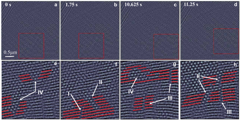
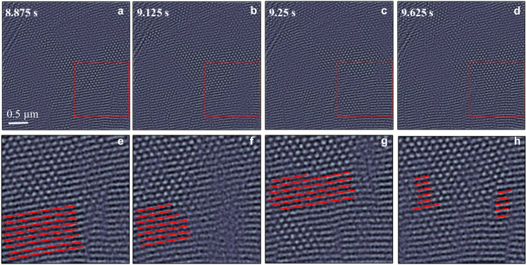
Experiments: To experimentally detect the different skyrmion configurations predicted above, we have investigated a 110 nm thin plate of Cu2OSeO3. The magnetic textures were imaged using a cryo-LTEM, see methods in the Supplemental Material. The applied magnetic field and temperature of the sample were held constant at 33 mT and 13 K, respectively, such that the system is close to the phase transition between the helical and the skyrmion phase. We recorded several movies and analyze here a selected movie of 100 frames with an integration time of 125 ms per frame. We observe a coexistence of helical and skyrmion domains which fluctuate with time, see Supplemental Material sup . Fig. 3(a-d) represents a m2 zoom of the total m2 micrograph at four different time points. One can clearly identify large regions dominated either by skyrmion crystals or the helical phase. The interesting feature here is the appearance of smaller clusters of skyrmions inside the helical phases. For clarity, we show a zoom of the real-space images marked by red squares in the lower panels (Fig. 3(e-h)). To highlight the different configurations of skyrmions, some of the helical regions are marked in red.
We can identify several frequently occurring defect clusters that can be related to the theoretical states shown in Fig.S1(e)-(h). The configurations I forming a line of skyrmions correspond to the state shown in Fig. S1(e). Also lines of dimers, compare Fig. S1(f), are often found and labeled by II in Fig. 3. Averaging over several such configurations of I and II, we find that the angle between the defect orientation and the ordering vector of the helix is given by for a line of skyrmions and for a line of dimers. This can be compared to and obtained within our simulations. We also find one further type of defect marked by III in Fig. 3 which cannot be interpreted as a bound state of skyrmions in a given helical background. Instead, in this “zipper” configuration the helical background on one side is shifted by half a lattice period. A simulation of such a structure is displayed in Fig. S1(g). In our simulation the binding energy per skyrmion for this configuration is lowered by approximately compared to the skyrmion line of Fig. S1(e) which implies that long defects of type I may transform into defects of type III. Furthermore, we observe all types of irregularly shaped clusters denoted by IV in Fig. 3. It is instructive to compare the formation of skyrmions in the helical and the ferromagnetic state. In the latter case, skyrmion-skyrmion interactions are repulsive Bogdanov (1995); Zhang et al. (2015); Müller (2017) and therefore no formation of skyrmion clusters is expected. We have checked this by performing experiments at magnetic fields of 100 mT to 150 mT, where only skyrmions in a ferromagnetic background occur. As expected, no cluster formation was observed by us, see Supplemental Material sup .
We also observe regions where the image is blurred at the location of defects. We believe that this effect arises from the motion of defects. Assuming a Gilbert damping of the order of , we estimate the 1d diffusion constant of a cluster of skyrmions sup in the absence of defects to be of the order of m2/s. Within the capturing time of a frame of our movie () a freely moving cluster can therefore move distances of the order of m. This estimate is consistent with large fluctuations which we see from frame to frame captured within our movie. Sharply resolved images correspond to clusters which are temporarily bound to defects presumably arising either from lattice defects or height variations of our films.
Conclusions: While sharing the same topology, skyrmions embedded in a helical or a ferromagnetic environment have very different properties. Our studies highlight one aspect of this: attractive interactions in the helical background let skymions arrange in lines and clusters. These lines and clusters have characteristic shapes and orientations which we identified both in our micromagnetic simulations and electron microscopy experiments. From the viewpoint of application, skyrmions in a helical background are potentially attractive since the helical stripes provide natural lanes along which skyrmions can be driven fast. However, one has to avoid the formation of zipper configuration which can, for example, be achieved in nanowires of suitable dimensions. The energy barrier for passing skyrmions between parallel lanes could be controlled for example with tailored light pulses or electric fields and will be explored in future experiments.
We thank the Deutsche Telekom Stiftung (J.M.), the Bonn-Cologne Graduate School of Physics and Astronomy BCGS (J.M.) and the CRC 1238 (project C04) of the German Science Foundation (A. R., J.M.) for financial support. J.R. thanks the Swiss National Science Foundation (SNSF) for funding through the Ambizione Fellowship PZ00P2_168035. Work at LUMES was supported by the National Center for Competence in Research Molecular Ultrafast Science and Technology (NCCR MUST), a research instrument of the SNSF. Work at LQM was supported by ERC project Controlled Quantum Effects and Spin Technology and SNSF (H.M.R.).
J. M., J. R. and P. H. contributed equally to this work.
References
- Dzyaloshinskii (1964) I. Dzyaloshinskii, Sov. Phys. JETP 19, 960 (1964).
- Bogdanov and Yablonskii (1989) A. Bogdanov and D. Yablonskii, Zh. Eksp. Teor. Fiz 95, 178 (1989).
- Bogdanov and Hubert (1994) A. Bogdanov and A. Hubert, J. Magn. Magn. Mater. 138, 255 (1994).
- Janson et al. (2014) O. Janson, I. Rousochatzakis, A. A. Tsirlin, M. Belesi, A. A. Leonov, U. K. Rößler, J. van den Brink, and H. Rosner, Nature Communications 5, 5376 (2014).
- Adams et al. (2012) T. Adams, A. Chacon, M. Wagner, A. Bauer, G. Brandl, B. Pedersen, H. Berger, P. Lemmens, and C. Pfleiderer, Phys. Rev. Lett. 108, 237204 (2012).
- Seki et al. (2012a) S. Seki, J.-H. Kim, D. Inosov, R. Georgii, B. Keimer, S. Ishiwata, and Y. Tokura, Phys. Rev. B 85, 220406 (2012a).
- Rajeswari et al. (2015) J. Rajeswari, P. Huang, G. F. Mancini, Y. Murooka, T. Latychevskaia, D. McGrouther, M. Cantoni, E. Baldini, J. S. White, A. Magrez, et al., Proc. Natl. Acad. Sci. U.S.A. 112, 14212 (2015).
- Seki et al. (2012b) S. Seki, X. Z. Yu, S. Ishiwata, and Y. Tokura, Science 336, 198 (2012b).
- Nagaosa and Tokura (2013) N. Nagaosa and Y. Tokura, Nat. Nanotech. 8, 899 (2013).
- Langner et al. (2014) M. C. Langner, S. Roy, S. K. Mishra, J. C. T. Lee, X. W. Shi, M. A. Hossain, Y.-D. Chuang, S. Seki, Y. Tokura, S. D. Kevan, and R. W. Schoenlein, Phys. Rev. Lett. 112, 167202 (2014).
- Zhang et al. (2016a) S. L. Zhang, A. Bauer, H. Berger, C. Pfleiderer, G. van der Laan, and T. Hesjedal, Applied Physics Letters 109, 192406 (2016a).
- Zhang et al. (2016b) S. L. Zhang, A. Bauer, H. Berger, C. Pfleiderer, G. van der Laan, and T. Hesjedal, Phys. Rev. B 93, 214420 (2016b).
- Zhang et al. (2016c) S. L. Zhang, A. Bauer, D. M. Burn, P. Milde, E. Neuber, L. M. Eng, H. Berger, C. Pfleiderer, G. van der Laan, and T. Hesjedal, Nano Letters 16, 3285 (2016c).
- Mühlbauer et al. (2009) S. Mühlbauer, B. Binz, F. Jonietz, C. Pfleiderer, A. Rosch, A. Neubauer, R. Georgii, and P. Böni, Science 323, 915 (2009).
- Milde et al. (2013) P. Milde, D. Köhler, J. Seidel, L. Eng, A. Bauer, A. Chacon, J. Kindervater, S. Mühlbauer, C. Pfleiderer, S. Buhrandt, et al., Science 340, 1076 (2013).
- Hagemeister J. et al. (2015) Hagemeister J., Romming N., von Bergmann K., Vedmedenko E. Y., and Wiesendanger R., Nat. Commun. 6, 8455 (2015).
- Müller and Rosch (2015) J. Müller and A. Rosch, Phys. Rev. B 91, 054410 (2015).
- Iwasaki et al. (2013a) J. Iwasaki, M. Mochizuki, and N. Nagaosa, Nat. Commun. 4, 1463 (2013a).
- Jonietz et al. (2010) F. Jonietz, S. Mühlbauer, C. Pfleiderer, A. Neubauer, W. Münzer, A. Bauer, T. Adams, R. Georgii, P. Böni, R. Duine, et al., Science 330, 1648 (2010).
- Yu et al. (2012) X. Yu, N. Kanazawa, W. Zhang, T. Nagai, T. Hara, K. Kimoto, Y. Matsui, Y. Onose, and Y. Tokura, Nat. Commun. 3, 988 (2012).
- Lin et al. (2014) S.-Z. Lin, C. D. Batista, C. Reichhardt, and A. Saxena, Phys. Rev. Lett. 112, 187203 (2014).
- Seki et al. (2012c) S. Seki, S. Ishiwata, and Y. Tokura, Phys. Rev. B 86, 060403 (2012c).
- White et al. (2012) J. S. White, I. Levatić, A. A. Omrani, N. Egetenmeyer, K. Prša, I. Živković, J. L. Gavilano, J. Kohlbrecher, M. Bartkowiak, H. Berger, and H. M. Rønnow, Journal of Physics: Condensed Matter 24, 432201 (2012).
- White et al. (2014) J. S. White, K. Prša, P. Huang, A. A. Omrani, I. Živković, M. Bartkowiak, H. Berger, A. Magrez, J. L. Gavilano, G. Nagy, J. Zang, and H. M. Rønnow, Phys. Rev. Lett. 113, 107203 (2014).
- Omrani et al. (2014) A. A. Omrani, J. S. White, K. Prša, I. Živković, H. Berger, A. Magrez, Y.-H. Liu, J. H. Han, and H. M. Rønnow, Phys. Rev. B 89, 064406 (2014).
- Koshibae and Nagaosa (2014) W. Koshibae and N. Nagaosa, Nat. Commun. 5, 5148 (2014).
- Ogawa et al. (2015) N. Ogawa, S. Seki, and Y. Tokura, Sci. Rep. 5, 9552 (2015).
- Berruto and Carbone (2017) G. Berruto and F. Carbone, (2017), in preparation.
- Sampaio et al. (2013) J. Sampaio, V. Cros, S. Rohart, A. Thiaville, and A. Fert, Nat. Nanotech. 8, 839 (2013).
- Woo et al. (2016) S. Woo, K. Litzius, B. Krüger, M.-Y. Im, L. Caretta, K. Richter, M. Mann, A. Krone, R. M. Reeve, M. Weigand, et al., Nat. Mater. 15, 501 (2016).
- Zhang et al. (2015) X. Zhang, G. Zhao, H. Fangohr, J. P. Liu, W. Xia, J. Xia, and F. Morvan, Sci. Rep. 5, 7643 (2015).
- Zhang et al. (2017) X. Zhang, J. Müller, J. Xia, M. Garst, X. Liu, and Y. Zhou, New Journal of Physics 19, 065001 (2017).
- Fert et al. (2013) A. Fert, V. Cros, and J. Sampaio, Nat. Nanotech. 8, 152 (2013).
- Müller (2017) J. Müller, New J. Phys. 19, 025002 (2017).
- Ezawa (2011) M. Ezawa, Phys. Rev. B 83, 100408 (2011).
- Schütte and Rosch (2014) C. Schütte and A. Rosch, Phys. Rev. B 90, 174432 (2014).
- Iwasaki et al. (2013b) J. Iwasaki, M. Mochizuki, and N. Nagaosa, Nat. Nanotech. 8, 742 (2013b).
- Müller et al. (2016) J. Müller, A. Rosch, and M. Garst, New J. Phys. 18, 065006 (2016).
- Kézsmárki et al. (2015) I. Kézsmárki, S. Bordács, P. Milde, E. Neuber, L. Eng, J. White, H. M. Rønnow, C. Dewhurst, M. Mochizuki, K. Yanai, et al., Nat. Mater. 14, 1116 (2015).
- Koshibae and Nagaosa (2016) W. Koshibae and N. Nagaosa, Nat. Commun. 7, 10542 (2016).
- Bogdanov (1995) A. Bogdanov, JEPT Lett. 62, 247 (1995).
- Leonov et al. (2016a) A. O. Leonov, T. L. Monchesky, J. C. Loudon, and A. N. Bogdanov, Journal of Physics: Condensed Matter 28, 35LT01 (2016a).
- Leonov et al. (2016b) A. O. Leonov, Y. Togawa, T. L. Monchesky, A. N. Bogdanov, J. Kishine, Y. Kousaka, M. Miyagawa, T. Koyama, J. Akimitsu, T. Koyama, K. Harada, S. Mori, D. McGrouther, R. Lamb, M. Krajnak, S. McVitie, R. L. Stamps, and K. Inoue, Phys. Rev. Lett. 117, 087202 (2016b).
- Loudon et al. (2017) J. C. Loudon, A. O. Leonov, A. N. Bogdanov, M. Ciomaga Hatnean, and G. Balakrishnan, ArXiv e-prints (2017), arXiv:1704.06876 [cond-mat.mes-hall] .
- Rózsa et al. (2016) L. Rózsa, A. Deák, E. Simon, R. Yanes, L. Udvardi, L. Szunyogh, and U. Nowak, Phys. Rev. Lett. 117, 157205 (2016).
- Zhao et al. (2016) X. Zhao, C. Jin, C. Wang, H. Du, J. Zang, M. Tian, R. Che, and Y. Zhang, Proceedings of the National Academy of Sciences 113, 4918 (2016).
- (47) See Supplemental Material.
- Thiele (1973) A. Thiele, Phys. Rev. Lett. 30, 230 (1973).
- Onose et al. (2012) Y. Onose, Y. Okamura, S. Seki, S. Ishiwata, and Y. Tokura, Phys. Rev. Lett. 109, 037603 (2012).
- Heinrich et al. (2011) B. Heinrich, C. Burrowes, E. Montoya, B. Kardasz, E. Girt, Y.-Y. Song, Y. Sun, and M. Wu, Phys. Rev. Lett. 107, 066604 (2011).
Supplemental Material for “Magnetic skyrmions and skyrmion clusters in the helical phase of Cu2OSeO3”
Jan Müller,1 Jayaraman Rajeswari,2 Ping Huang,3 Yoshie Murooka,2 Henrik M. Rønnow,3 Fabrizio Carbone,2 and Achim Rosch
1Institute for Theoretical Physics, University of Cologne, D-50937 Cologne, Germany
2Laboratory for Ultrafast Microscopy and Electron Scattering (LUMES), Institute of Physics, EPFL, CH-1015 Lausanne, Switzerland
3Laboratory for Quantum Magnetism (LQM), Institute of Physics, EPFL, CH-1015 Lausanne, Switzerland
We present some details on the micromagnetic simulations, the calculation of interaction potentials and diffusion constants. Furthermore, we give experimental details and show that skyrmions close to the phase transition to the ferromagnetic state do not display the characteristic cluster formation observed in the helical phase.
I I. Micromagnetic Simulations
We consider a two-dimensional plane with the magnetization represented by a three-dimensional vector field. The free energy functional, , includes exchange interaction , Dzyaloshinskii-Moriya-interaction and an external magnetic field :
| (S1) |
where is the normalized magnetization. Since the theory is continuous, we introduce dimensionless scales for the momentum , energy per layer and magnetic field
| (S2) |
For numerical implementation, we discretize the system, typically using 22 spins per pitch of the helix. For the calculation of energy minima we prepare an initial magnetic texture and let it then relax by a fourth order Runge-Kutta integration of the equation
| (S3) |
with the component of the effective magnetic field perpendicular to the magnetization. This equation can be interpreted as the Landau-Lifshitz-Gilbert equation where the precession term is omitted. For the calculation of interaction potentials we fixed a couple of spins (one to nine) in the center of the monomers during the minimization and hence ensure that the distance is preserved during the minimization process. We have checked that the results are approximately independent of the number of fixed spins.
I.1 A. Localization of topological charge
We compute the topological charge density from the relaxed monomer, anti-monomer and dimer configurations via the formula
| (S4) |
and show the results in Fig. S1. What should be noticed here is that the charge distribution is indeed localized. Furthermore, upon integration we find that the total charge is for the interstitial (a) and the H-shaped skyrmion (b), for the antiskyrmion (c) and for the skyrmion dimer (d).
I.2 B. Dimer potentials and energetics of clusters
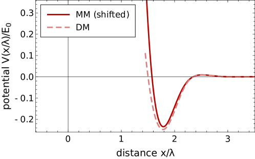
In the main text the monomer-monomer potentials are discussed. Figures S2 and S3 show the interaction potential of a dimer (i.e. a bound pair of monomers) with a monomer on the same lane (Fig. S2, red dashed) and on the neighboring lane (Fig. S3, blue dashed). We emphasize that these interactions can be reduced to the potentials of only monomer interaction by additionally plotting the interaction between monomers in the same setups (solid lines respectively). These two-particle interaction potentials are shifted on the x-axis such that they match the positions of the single monomer and the nearest other monomer of the full three-particle potentials. In the case of the dimer and the monomer being placed on neighboring lanes, Fig. S3, the monomer can be located between the two constituents of the dimer and thus feels both of them. Here the full three-particle potential can be accurately described by a superposition of two two-particle interaction potentials accordingly shifted (solid green).
The energy of a cluster of skyrmions can then be estimated by simply adding the energies at the interaction minima. For example, the energy of the -skyrmion cluster, Fig. 1(h) in the main text, is the sum of in total monomer pairs on the same lane and monomer pairs on neighboring lanes. This gives a total binding energy of compared to from the full relaxation.
I.3 C. Diffusion
The dynamics of the magnetization are governed by the Landau-Lifshitz-Gilbert equation (LLG). In the presence of thermal fluctuations, these equations are made stochastic by adding a fluctuating term to the effective magnetic field . This fluctuating field has to vanish on average
| (S5) |
and is uncorrelated with a suitable normalization factor
| (S6) |
where is the Gilbert damping, the gyromagnetic ratio and the saturation magnetization. Application of the Thiele ansatz, where the magnetization is assumed a rigid object, yields the thermal stochastic force on a skyrmion. Its average properties follow directly from the LLG after the Thiele procedure
| (S7) |
where is the corresponding entry of the dissipation matrix, including the spin density and the thickness of the sample. is the normalized magnetization.
Via the Thiele equation, the thermal force relates directly to the velocity of the skyrmion. The resulting mean squared displacement for the free motion in two spatial dimensions follows to vanish linear in the damping ,
| (S8) |
which can be understood as the strong circular motion of the skyrmion due to a dominant Magnus force if the damping is low. However, the motion of a skyrmion in the helical background is effectively confined to only one dimension. In this case, a low damping results in a fast velocity since the mean squared displacement in the helical lane after a time follows as
| (S9) |
where we obtained the diffusion constant . Numerical evaluation of the dimensionless integral in the dissipation matrix coefficient yields . We used for the spin density , the sample thickness , the temperature and estimated a Gilbert damping of . Consequently, we obtain an estimate for the diffusion constant of the order . Since the dissipation element is linear in the number of skyrmions , the diffusion constant scales as .
II II. Experimental details
A high-quality single crystal of Cu2OSeO3 was grown by the chemical vapor transport method. The single crystal was aligned and cut into a cube so that the three main directions correspond to , and , respectively. Then, choosing as the main surface, the cube was cut into slices of mm thickness. The sample was thinned to about 110 nm by Focused Ion Beam (FIB) technique.
The magnetic structures of the sample were investigated using the FEI Titan Themis cryo-LTEM CIM after zero-field cooling. The microscope equipped with a field emission gun was operated at 300 kV in the Fresnel mode. The magnetic field was applied normal to the sample surface along the direction.
III III. Fluctuation of helical and skyrmion domains
Figure S4 presents four different frames from the movie indicating the coexistence as well as the fluctuation of helical and skyrmion domains. Magnified views of the highlighted red squares are shown in the bottom panels. For clarity, some of the helical regions are drawn in red to underline their movement as function of time.
IV IV. Skyrmions in a ferromagnetic background
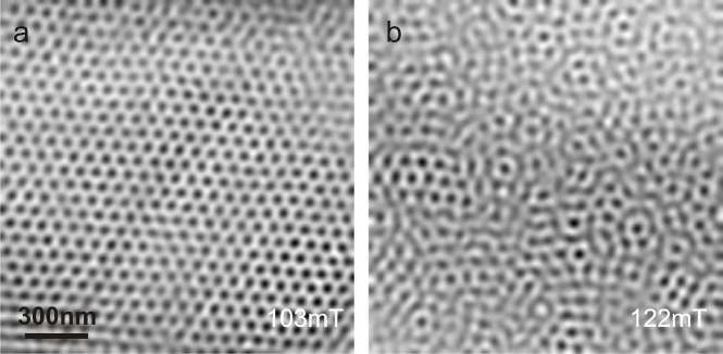
Figure S5 shows Lorentz micrographs upon increasing magnetic fields as the system passes from the skyrmion to the ferrimagnetic or conical phase. Since our method averages the signal over the sample thickness, we can not clearly distinguish between these two phases which occur at higher fields. As discussed in the main text, the interactions between skyrmions depend on the precise phase in which they are embedded. While skyrmions in the helical background form characteristic line defects, no such clusters can be found in Fig. S5b, where skyrmions are embedded in a polarized background.
V V. Phase diagram
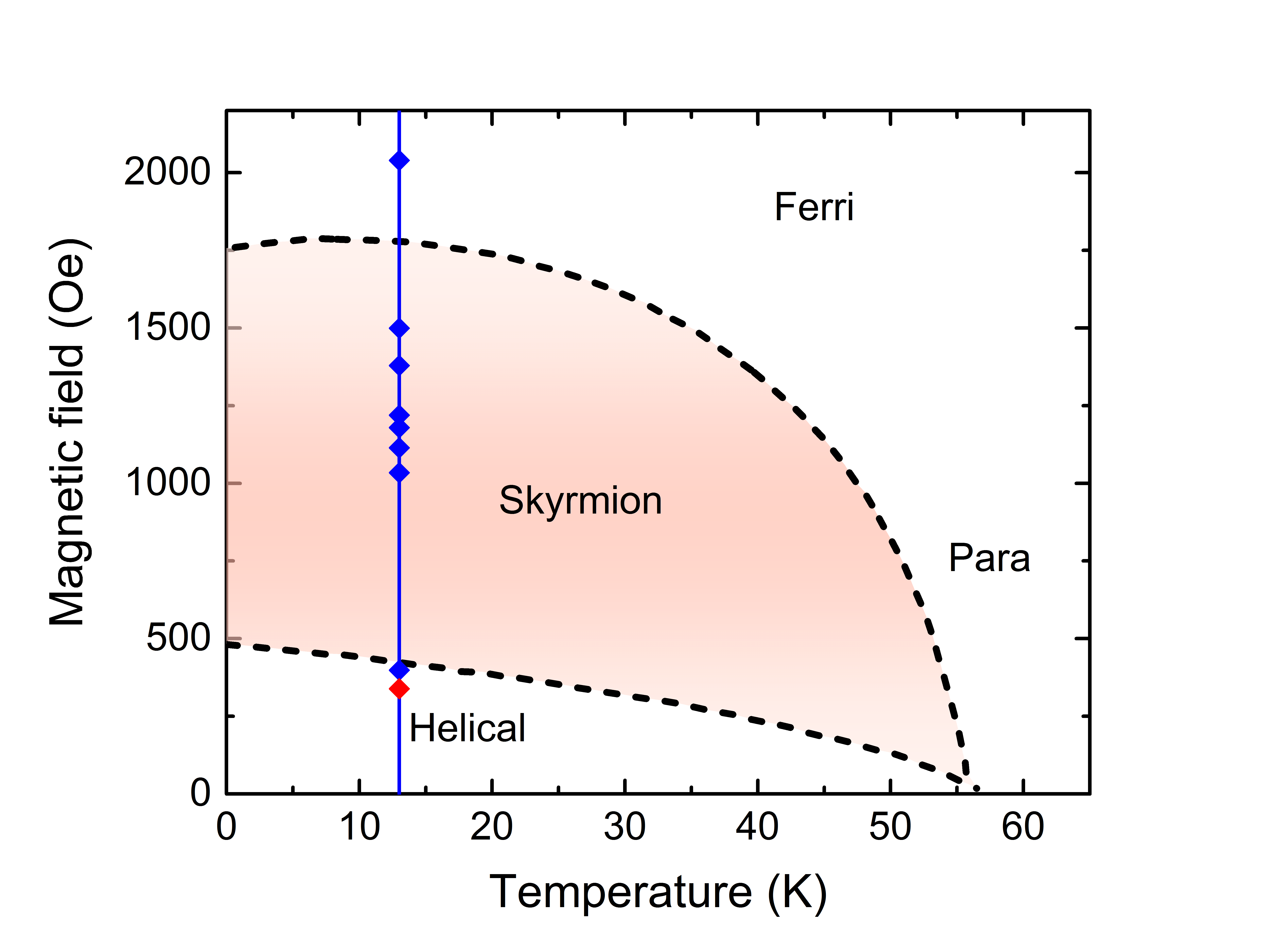
Figure S6 shows a schematic phase diagram for a thin film of Cu2OSeO3. The schematic phase diagram is a sketch based on the data points which we have taken from Ref. 2. We have marked the positions in the phase diagram at which we record movies. The red diamond marks the point in phase space (K, mT) for which the movies in the main text were recorded. The blue diamonds mark other experimental parameters for which we have performed our measurements, among which are also the frames for the decay into the polarized phase, shown in Fig. S5.
References
- (1) “CIME EPFL,” http://cime.epfl.ch/titan.
- Seki et al. (2012b) S. Seki, X. Z. Yu, S. Ishiwata, and Y. Tokura, Science 336, 198 (2012b).