Magnetization curves of geometrically frustrated exchange-biased FM/AFM bilayers
Abstract
We consider a ferromagnetic/antiferromagnetic bilayer on a triangular lattice in the framework of the planar Heisenberg model. The impact of the geometrical frustration in this system on the magnetization curves and the exchange bias phenomenon is studied. The magnetization curves and the phase diagram for such systems are obtained. We observe horizontal plateaus and a split of the hysteresis loop on the magnetization curves. It is shown that the shift of the hysteresis loop (exchange bias) occurs for the systems with a magnetically hard antiferromagnet.
pacs:
75.60.Ej, 75.70.CnI 1. Introduction
In this paper we study the exchange bias phenomenon in the ferromagnetic/ antiferromagnetic bilayer (FM/AFM) with the geometrical frustration. The exchange bias phenomenon consists in the shift of the magnetic hysteresis loop along the external magnetic field axis 1 . Moreover, some experimental studies show the asymmetry of a magnetization curve, the appearance of horizontal plateaus, and the split of hysteresis loops. These effects are widely studied theoretically and experimentally in layered FM/AFM systems but still have no comprehensive explanation. Despite a large number of works, the influence of the geometrical frustration in the bilayer system on the exchange bias has been little studied yet frust , frust-exp . The geometrical frustration appears when the minimum of the system energy does not correspond the minimum of all local interactions. The triangular lattice with the AFM interaction between each pair of spins is a simplest example of the geometrically frustrated system. In this system the frustration appears because of incompatibility between the local interactions and the lattice geometry. In this paper the FM/AFM bilayers on the triangular lattice are studied in the framework of the planar Heisenberg model with periodic boundary conditions. The outline of the paper is as follows. In Section 2 we introduce a layered system made of one FM and one AFM monolayers on a triangular lattice. Section 3 is devoted to the study of the FM/AFM structure with fixed (so called frozen) AFM magnetic moments. The paper is completed by the Concluding remarks.
II 2. FM/AFM bilayer on triangular lattice
In this section we consider a FM/AFM bilayer made of two monolayers on the triangular lattice. The interaction through the FM/AFM interface is considered to be ferromagnetic. The exchange interactions in the FM and AFM films are given by the parameters and , respectively. We assume a strong easy-plane anisotropy both in the AFM (layer A) and FM (layer B) layers and an additional single-ion anisotropy , in the easy planes of the FM and AFM subsystems. We consider different values of the magnetic anisotropy for the AFM and FM planes . It is assumed that the external magnetic field is directed along the easy axis.The magnetic states of the magnetization vectors in this bilayer are given by the rotational angles of spins in the easy plane. The magnetic energy of the system is given by:
| (1) |
where the first three summations run over all nearest neighbours and the next three over the spins in the respective layers. Assuming spin uniformity in the respective sublattices the possible equilibrium states are given by the equations:
| (2) |
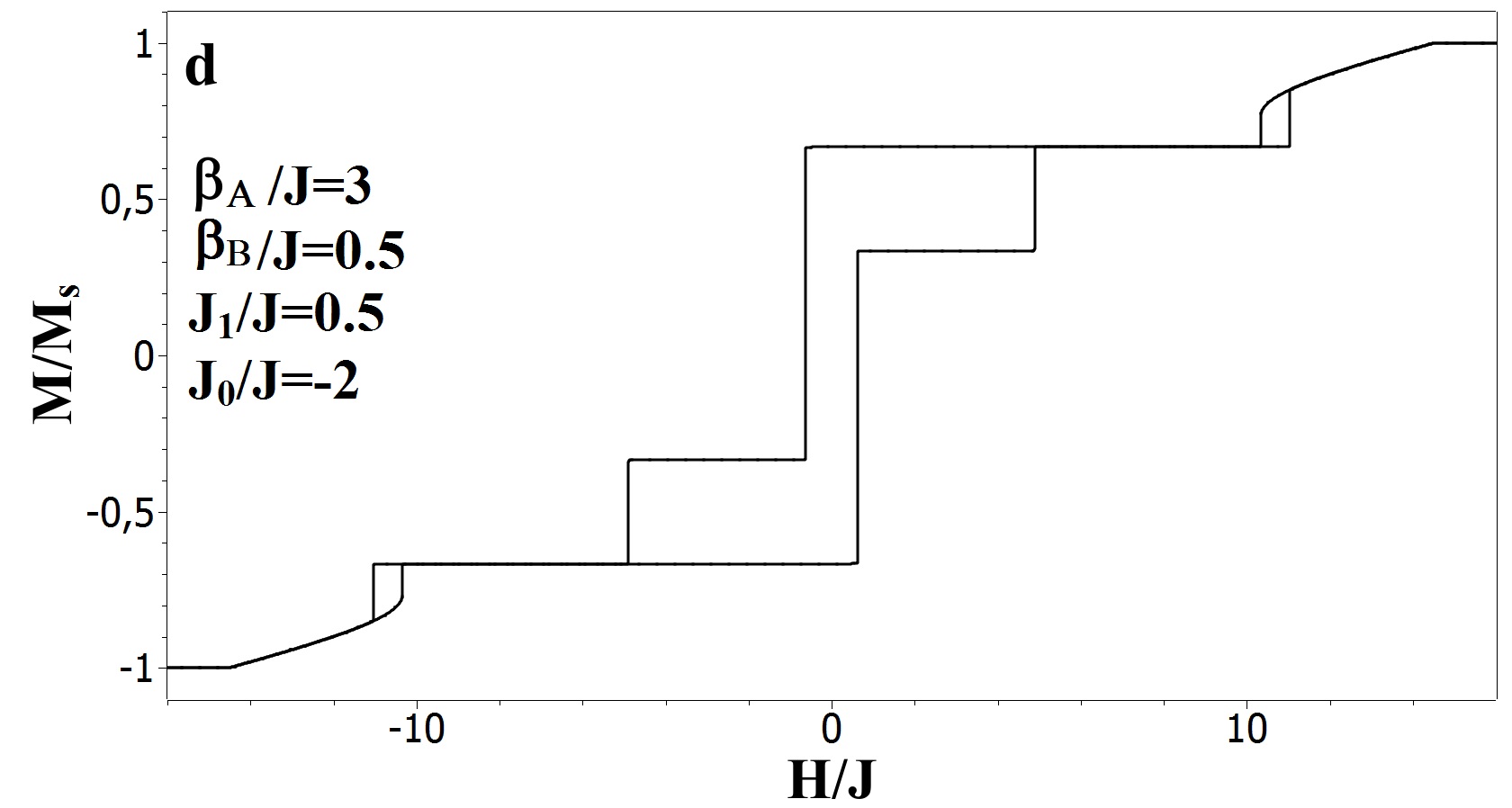
where indexes and correspond to the planes (FM or AFM) and to the sublattices in these planes respectively. The solutions of these equations are the parallel structures (), the non-collinear structures (), and the antiparallel structures which correspond to the horizontal plateaus (), where , so all magnetic moments are laying along the field exept one in the layer A that has an opposite direction. The second type of horizontal plateaus cooresponds to a , where .
The transition from the collinear phase to the canted phase corresponds to the bifurcation of the solutions . In the neighborhood of the bifurcation point, there are canted solutions of Eq. (2) which are infinitesimally close to the collinear states. To find this point, we linearize these equations with respect to the angles and look for the nonzero solutions of the linearized equations. The analysis of the stability of the phase can be done in a similar way.
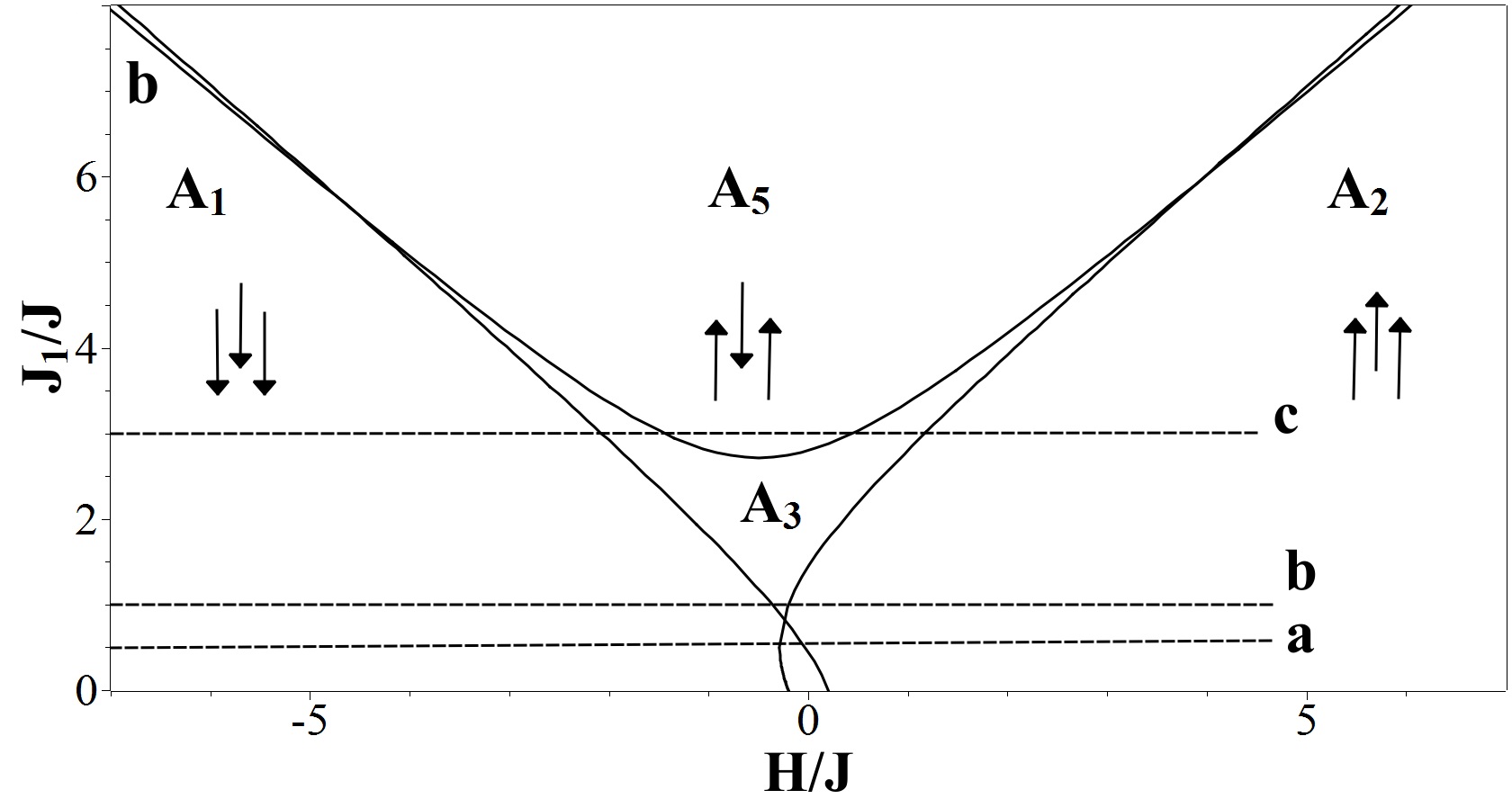
The areas of the existence of the identified structures are given in Fig.1. The arrows show the direction of magnetization.
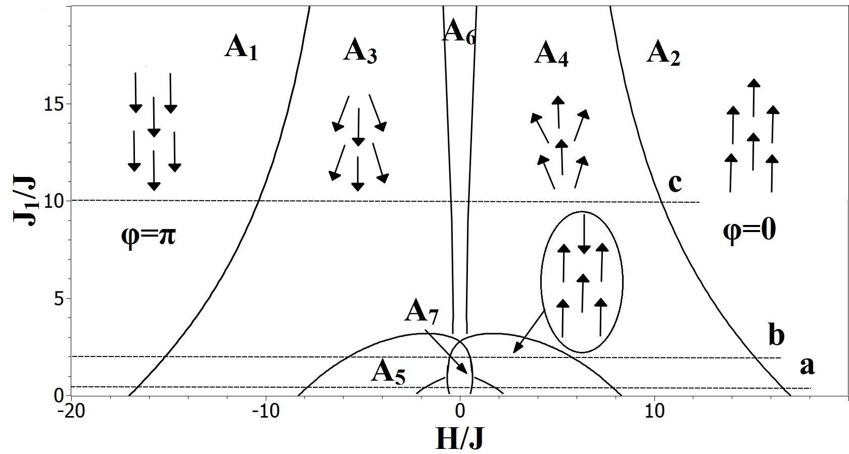
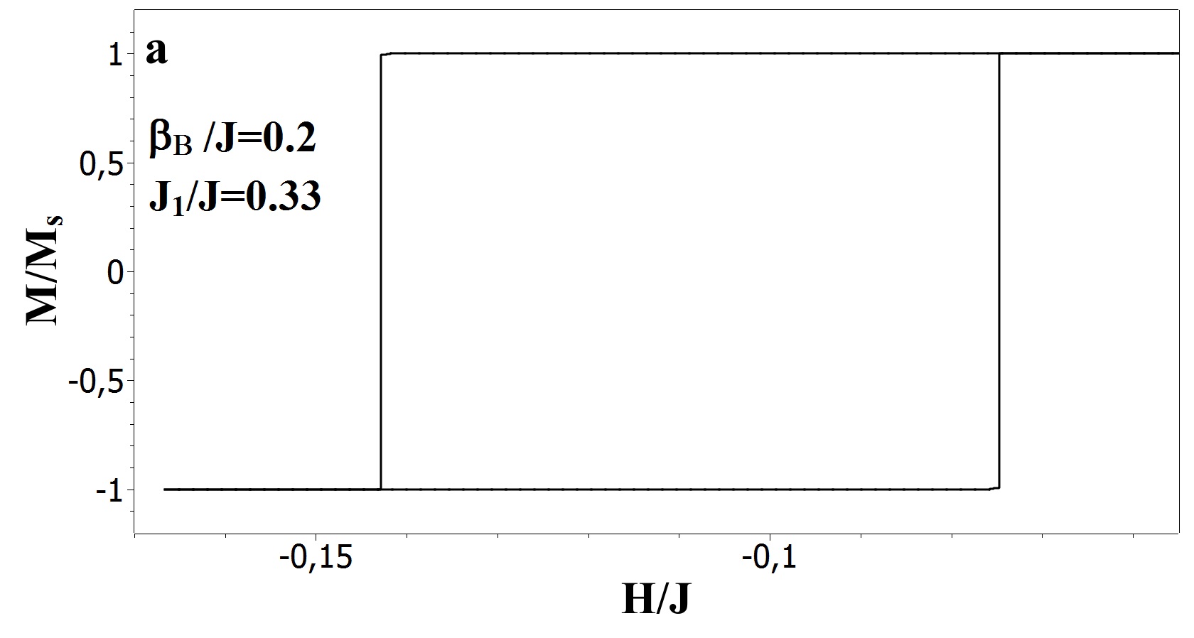
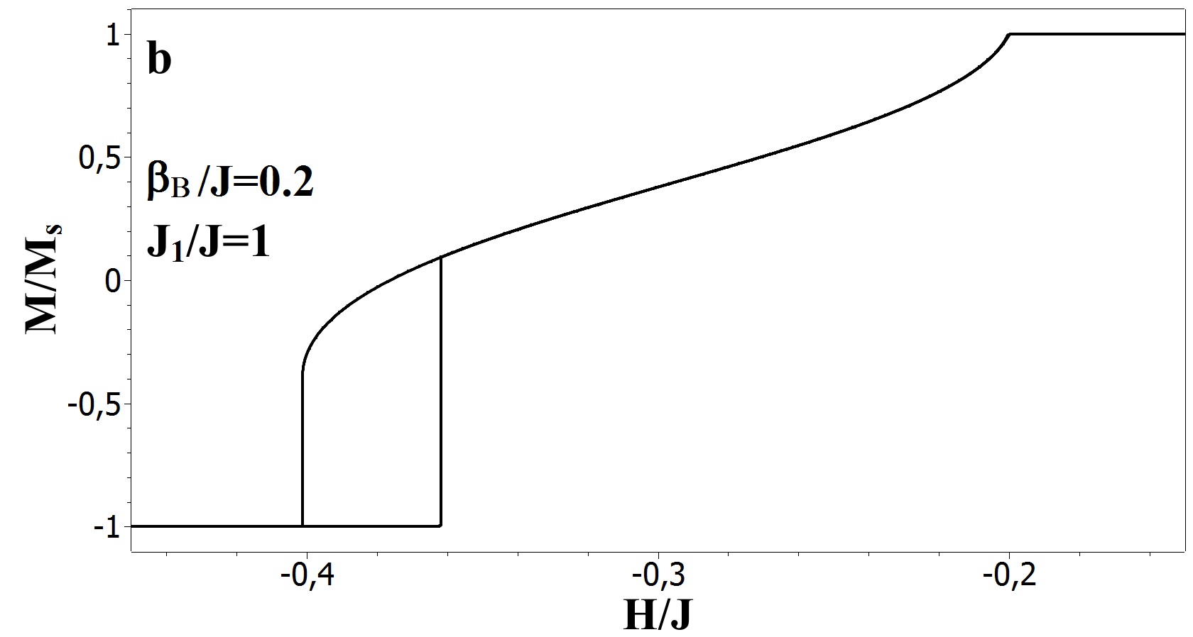
The parameter regions A1 and A2 in Fig.1 correspond to the parallel states in the FM/AFM bilayer, A3 and A4 to the non-collinear structures, and A5 to the existence of the antiparallel states. The small area corresponds to the coexistence of horizontal plateaus (see hystersis loop in the Fig.2a,b,d). The area is the domain of the existence of the hysteresis loop in the magnetization curves. In the areas the external magnetic field is big enough to reverse both FM and AFM and the magnetization vectors in both layers have the same direction. On the contrary, the direction of magnetic moments of the layer A and layer B in the other areas can be different as for example in the horizontal plateau, described above. The lines for the boundaries of the parallel and antiparallel states were obtained analytically from Eq. (2), while the other curves could only be obtained numerically.
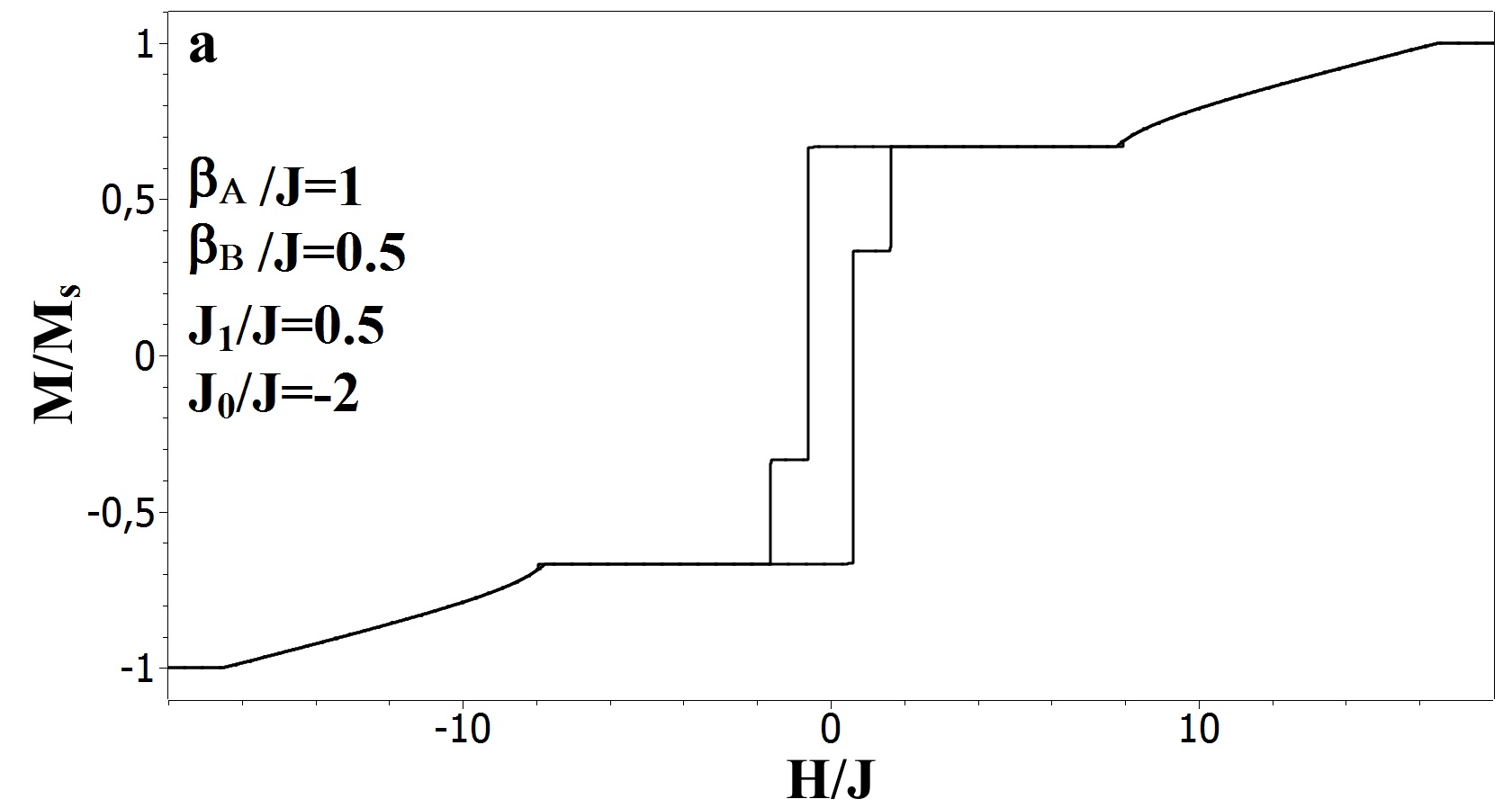
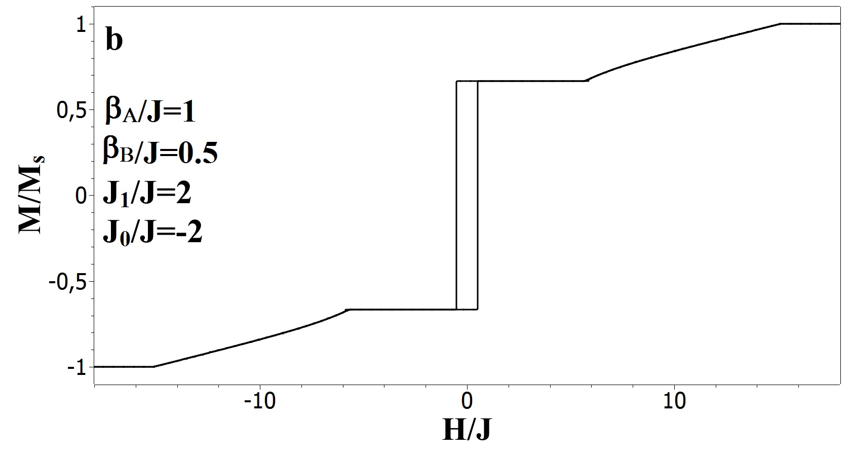
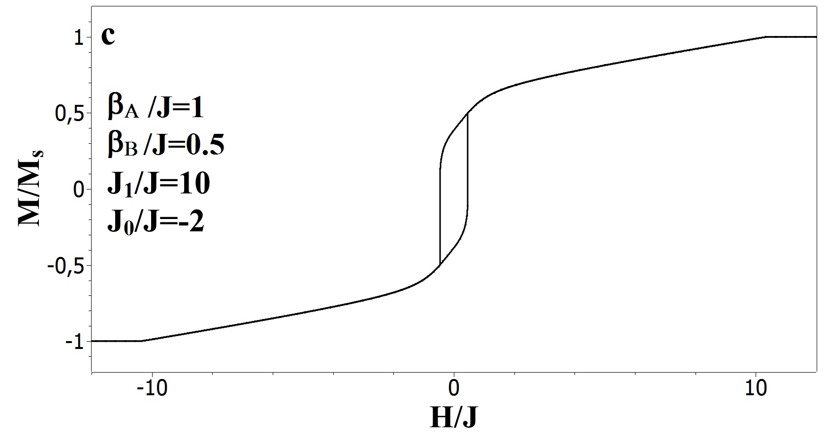
The total magnetization of FM/AFM bilayer is given by the formula: . The hysteresis loops were obtained for different values of (Fig.2a-c) and (Fig.2a,d).
III 3. The case of frozen AFM
In this section the AFM layer in the FM/AFM bilayer is considered to be magnetically hard, i.e., for the magnetic fields that are less than the spin-flop transition, its magnetic structure is fixed during the entire magnetization reversalkiwi . One can obtain the frozen AFM layer as a surface of a staked AFM with large anisotropy. In this AFM stack the structure of each layer is ferrimagnetic (), with magnetic moments in each layer having opposite direction with their nearest neighbors in the neighbouring layers and thus the total magnetization of the AFM stack is zero. We consider a case of an uncompensated FM/AFM interface. In particular, the collinear structure is considered with two magnetic moments in the triangular plaquette laying opposite to the external magnetic field and one magnetic moment is laying along the field. The uncompensated AFM interface can appear in the following way. Because of the frustration, a noncollinear structure with zero magnetization appears in the AFM layer in zero magnetic field. Due to the interaction with the FM layer the spins in the AFM layer deviate from their original positions and thus form an uncompensated AFM interface frust .
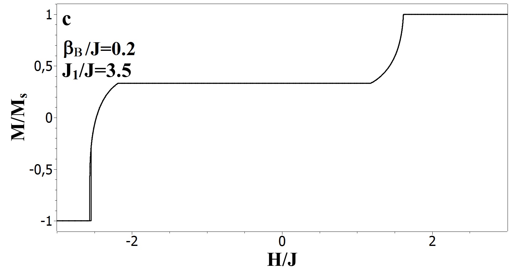
The areas of existence of the paralell , non-collinear , and antiparallel phases (Fig.3) and the hysteresis loops (Fig.4) were obtained in a way similar to that from the previous section. It is shown that in this model the shifted magnetization curve can be asymmetric (Fig.4 b,c) and has horizontal plateaus (Fig.3 c). In this section the curves correspond to the FM layer, while the magnetic moments of AFM are fixed and do not contribute to the magnetization.
IV Conclusions
In the framework of the planar Heisenberg model the magnetization curves of the FM/AFM bilayer on a triangular lattice are studied. We have considered the cases of the non-frozen and frozen AFM. The hysteresis loops have been obtained for different values of the exchange interaction and the magnetic anisotropy. The exchange bias is observed in the case of the frozen AFM. Horizontal plateaus and the hysteresis loops are observed for both frozen and non-frozen AFM cases. Phase diagrams have been calculated for selected values of the parameters.
V Acknowledgement
This work was supported by the Scientific Grant Agency of Ministry of Education of Slovak Republic (Grant No. 1/0331/15) and by the National Scholarhip Programme of the Slovak Republic.
References
- (1) W.H. Meiklejohn, C.P. Bean, Phys. Rev., 1413 (1956). DOI: 10.1103/PhysRev.105.904.
- (2) C. Mitsumata, A. Sakuma, K. Fukamichi, IEEE Trans. on Mag., , 10 (2005). DOI: 10.1109/TMAG.2005.855223
- (3) P.Song, G.K. Li, L. Ma, C.M. Zhen, D.L. Hou, W.H. Wang, E.K. Lui, J.L. Chen, G.H. Wu, J. of App. Phys. , 213907 (2014). DOI: 10.1063/1.4881527
- (4) M.Kiwi, J.Mejfa-Lopez, R.Portugal, R.Ramirez, Europ.Lett. , 573 (1999).DOI: 10.1209/epl/i1999-00522-9.