Demonstration of efficient nonreciprocity in a microwave optomechanical circuit
Abstract
The ability to engineer nonreciprocal interactions is an essential tool in modern communication technology as well as a powerful resource for building quantum networks. Aside from large reverse isolation, a nonreciprocal device suitable for applications must also have high efficiency (low insertion loss) and low output noise. Recent theoretical and experimental studies have shown that nonreciprocal behavior can be achieved in optomechanical systems, but performance in these last two attributes has been limited. Here we demonstrate an efficient, frequency-converting microwave isolator based on the optomechanical interactions between electromagnetic fields and a mechanically compliant vacuum gap capacitor. We achieve simultaneous reverse isolation of more than 20 dB and insertion loss less than 1.5 dB over a bandwidth of 5 kHz. We characterize the nonreciprocal noise performance of the device, observing that the residual thermal noise from the mechanical environments is routed solely to the input of the isolator. Our measurements show quantitative agreement with a general coupled-mode theory. Unlike conventional isolators and circulators, these compact nonreciprocal devices do not require a static magnetic field, and they allow for dynamic control of the direction of isolation. With these advantages, similar devices could enable programmable, high-efficiency connections between disparate nodes of quantum networks, even efficiently bridging the microwave and optical domains.
Many branches of physics and engineering employ nonreciprocal devices to route signals along desired paths of measurement networks. Conceptually, the simplest nonreciprocal element is the isolator, a two-port device that transmits signals from the first to the second port but strongly attenuates in the reverse direction JalasPetrovEichEtAl2013 . Placing an ideal isolator (or its close relative, the circulator) between two systems allows the first system to influence the second but not vice versa. This nonreciprocal functionality enables, for example, telecommunication antennas to transmit and receive signals at the same time. Another example relevant for future applications is quantum signal processing, where the strict demands of quantum measurement require isolators with high performance in several metrics, including not only large isolation, but also high efficiency and low noise Kimble2008 .
Well-established technology uses magnetic materials to achieve nonreciprocity for both microwave and optical frequencies Polder1949 ; Hogan1952 ; ApletCarson1964 . While these conventional devices have enabled much of the progress in classical and quantum signal processing, overcoming their limitations could lead to exciting new developments in both areas. For example, these components are typically bulky, not chip-compatible, and because they require strong magnetic fields, are incompatible with superconducting technology. Signal losses due to these conventional nonreciprocal devices have now become the bottleneck for the overall efficiency of, for example, state-of-the-art microwave measurements RochFlurinNguyenEtAl2012 ; KindelSchroerLehnert2016 ; ClarkLecocqSimmondsEtAl2016 .
In recent years, there has been interest in developing nonmagnetic nonreciprocal devices to replace conventional isolators and overcome the limitations discussed above for superconducting microwave applications EstepSounasSoricEtAl2014 ; KamalRoyClarkeEtAl2014 ; AbdoSliwaShankarEtAl2014 ; KerckhoffLalumiereChapmanEtAl2015 ; SliwaHatridgeNarlaEtAl2015 ; MacklinOextquotesingleBrienHoverEtAl2015 ; MetelmannClerk2015 as well as limitations that arise in optical and room temperature isolation KangButschRussell2011 . Schemes based on coupled-mode physics can break reciprocity without a static magnetic field if the coupling is parametrically modulated in time JalasPetrovEichEtAl2013 . Producing isolation further requires the coherent interference of two paths from one port to another as well a reservoir to absorb the backward-propagating power MetelmannClerk2015 ; Ranzani2015 . These schemes are particularly promising because they can naturally integrate with existing chip-based superconducting technology Ranzani2015 ; AbdoSliwaFrunzioEtAl2013 ; AbdoSliwaShankarEtAl2014 ; KamalClarkeDevoret2011 ; KamalRoyClarkeEtAl2014 ; LecocqRanzani2017 .
One route for efficient parametric nonreciprocity in the microwave domain is to use Josephson junctions to couple superconducting circuits SliwaHatridgeNarlaEtAl2015 ; LecocqRanzani2017 . More recently, theoretical proposals HafeziRabl2012 ; Ranzani2015 ; MetelmannClerk2015 ; XuLiChenEtAl2016 and experiments ShenZhangChenEtAl2016 ; RuesinkMiriAluEtAl2016 ; FangLuoMetelmannEtAl2017 have begun exploring the parametric coupling between an electromagnetic cavity and a mechanical oscillator as an alternative mode-coupling mechanism for nonreciprocity. These optomechanical systems are attractive because of their wide applicability beyond microwave frequencies and cryogenic environments. For example, efficient, reciprocal frequency conversion using optomechanics has already been demonstrated in both the microwave LecocqClarkSimmondsEtAl2016 and optical LiuDavancoAksyukEtAl2013 ; LiDavancoSrinivasan2016 frequency bands, as well as in conversion between the two AndrewsLehnert2014 . Nonreciprocal optomechanical devices, however, have yet to show the efficiencies and noise properties needed for most applications.
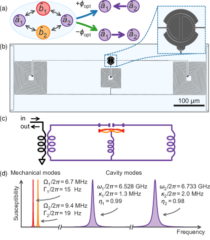
Combining two independent optomechanical frequency converters gives a natural way to achieve the interference needed for nonreciprocity. Here we realize this interference by simultaneously coupling two electromagnetic cavity modes to two distinct vibrational modes of a mechanical membrane. We illustrate this concept for achieving nonreciprocal frequency conversion between the two cavities in Fig. 1(a).
To understand the optomechanical isolator, we begin with the fundamental parametric interaction between an electromagnetic cavity and a mechanical oscillator AspelmeyerKippenbergMarquardt2014 . A general multimode cavity optomechanical system consists of a set of cavity resonances and mechanical modes. Consider a given cavity mode with resonant frequency and linewidth and a given mechanical mode with frequency and intrinsic linewidth , obeying . The position of the mechanical oscillator tunes the cavity frequency, providing the mechanism of coupling. Analysis of the equations of motion for the cavity and mechanical mode annihilation operators, and , shows that a strong electromagnetic field (the drive) applied at a frequency near the red sideband (defined by ) induces an effective beam-splitter interaction. The interaction Hamiltonian is , where is the reduced Planck constant, and the coupling rate is a complex number with phase and amplitude set by the drive. We parameterize the coupling strength in terms of the cooperativity .
Our optomechanical isolator is fully described by the general theory of linear coupled-mode systems Louisell1960 ; Ranzani2015 ; LecocqRanzani2017 . In the quantum input-output formalism Gardiner1985 , each mode couples to its environmental input and output operators and through the standard input-output boundary conditions. The scattering matrix elements are defined as the ratios of output to input field amplitudes, , where indicates expectation value. Demonstrating an efficient isolator requires maximizing the forward transmission while minimizing the reverse transmission .
We experimentally create a system consisting of two cavity modes and two mechanical modes by designing and fabricating a superconducting circuit of aluminum on a sapphire substrate CicakLiStrongEtAl2010 ; TeufelLiAllmanEtAl2011 ; LecocqTeufelAumentadoEtAl2015 , as shown and characterized in Fig. 1(b–d). A vacuum-gap capacitor combined with an inductive network defines two microwave cavities with resonant frequencies GHz and GHz and linewidths MHz and MHz. We design the cavities to be highly overcoupled so that the intentional inductive coupling rate to the measurement line, , dominates the total dissipation rate of each cavity, . The coupling efficiencies for each cavity, defined as , are measured to be and . The vacuum-gap capacitor has a mechanically compliant top plate that vibrates with several spectrally distinct mode frequencies. In this experiment, we use the two lowest-frequency vibrational modes at MHz and MHz with intrinsic linewidths Hz and Hz, as determined by independent measurements of the energy dissipation rate. We place the device in a dilution cryostat with a base temperature of 19 mK and interrogate the circuit with signals routed from microwave generators and a vector network analyzer. From room temperature components, input signals pass through attenuators, reflect off the device at a circulator, and pass through a cryogenic high-electron-mobility transistor amplifier, with more amplification at room temperature. We operate the device as a single physical port measured in reflection; ports 1 and 2 used hereafter refer to input or output signals near the resonant frequencies of cavities 1 and 2.
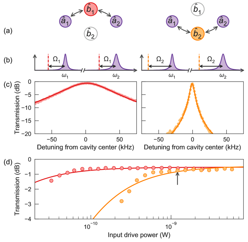
As reciprocal frequency conversion forms the basis for the optomechanical isolator, we first demonstrate this process through each mechanical mode (Fig. 2). In this scheme, one microwave drive is applied at each cavity’s red sideband with respect to a single mechanical mode; a signal entering one cavity down-converts to the mechanical mode and then up-converts to the other cavity (Fig. 2a,b).
In Fig. 2(c) we show the reciprocal transmission from one cavity to the other as a function of detuning from the cavity center frequencies. We calibrate the scattering parameters using methods described previously AndrewsLehnert2014 ; LecocqClarkSimmondsEtAl2016 . A drive power of approximately 1 nW damps mechanical mode 1 (left) to about 70 kHz and mode 2 (right) to 7 kHz. These damping rates are comparable to those used later in the nonreciprocal scheme. We achieve transmission above dB through each mode, limited by cavity loss and pump strength imbalance. At our highest drive powers, the bandwidths of frequency conversion through the mechanical modes reach 150 kHz and 35 kHz. Our frequency converter operates in the high cooperativity limit, as evidenced by the large ratios of damped mechanical linewidths to intrinsic linewidths and the plateau in transmission versus input power, shown in Fig. 2(c).
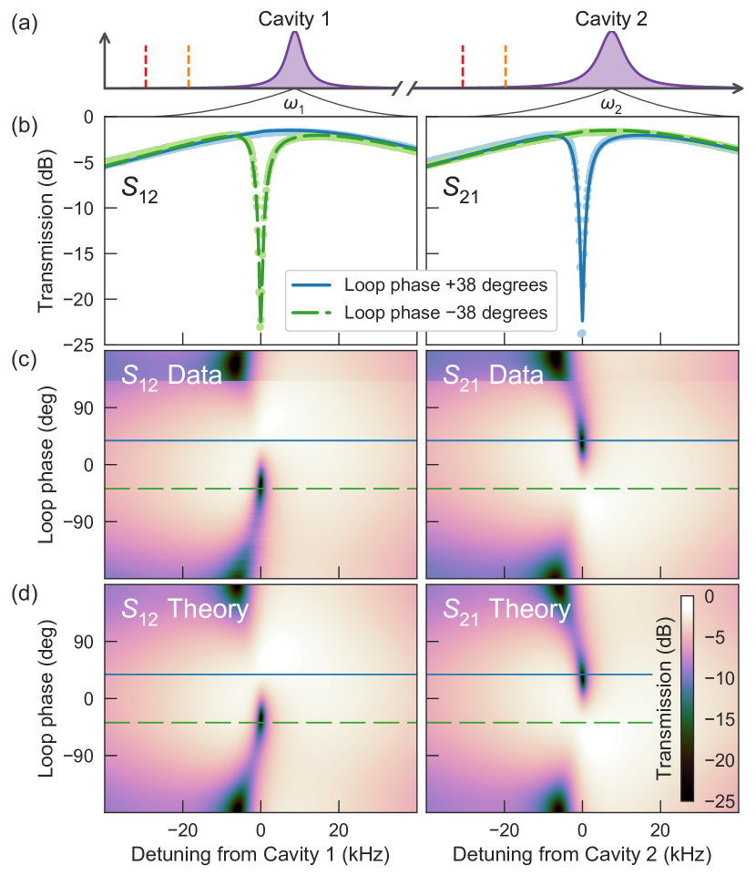
Now, to realize the optomechanical isolator, we drive two branches of mechanically-mediated frequency conversion simultaneously. Figure 3(a) shows the frequency space diagram of the experiment, with dashed lines indicating the frequencies of the four drives. Ideal isolation maximizes the magnitude of the transmission difference, defined as . Transmission difference lies between and , making it a useful metric because it simultaneously favors high reverse isolation and low insertion loss, both important for quantum signals applications.
To achieve ideal isolation at the cavity resonances, the powers, frequencies, and relative phases of the four drives must be tuned to optimal values. Assuming the cavity linewidths are much larger than the mechanical mode linewidths and the optomechanical cooperativities are large, we can derive closed-form solutions for the optimal drive parameters and the scattering matrix by analytically maximizing the function (see supplementary information). First, the drive powers should be such that the cooperativities for all four optomechanical couplings are equal (let their shared value be ). Isolation performance increases with this cooperativity as . The second condition sets the drive frequencies. One might expect that tuning the four drives to the exact red sideband frequencies would be ideal. In fact, this configuration leads to reciprocal behavior precisely at the cavity center frequencies. Permitting detuning of the drive pairs from the red sidebands allows nonreciprocal transmission to occur on resonance with the cavities. The optimal drive detunings are , where is the detuning from the red sideband of the drives that connect to the th mechanical mode. The third important condition relates to the optimal relative drive phases. A signal traversing the loop in mode space acquires a phase, called the loop phase . Because the frequency conversion processes are parametric, this phase is related to the sum of the relative phases of the four drives, making it a dynamically tunable parameter. Under the assumptions mentioned above, the optimal values of the loop phase are .
After substituting these optimized drive parameters, and further letting and taking the large limit, the full scattering matrix becomes
| (1) |
where the mode basis is ordered . We see that the upper left corner defines the ideal isolator, perfectly isolating cavity 1 from cavity 2. The other matrix elements describe scattering of signals input to the mechanical modes. At the opposite loop phase, the scattering matrix becomes the transpose of that shown above, isolating cavity 2 from cavity 1.
In contrast to reciprocal frequency conversion, the mechanical dissipation plays a key role in the nonreciprocal behavior of the device. This is a consequence of power conservation; isolation can only occur if power entering a cavity mode can be completely routed into the mechanical environments. The mechanical modes are coupled to their environment with fixed rates . So, while the bandwidth of reciprocal mechanically-mediated frequency conversion increases with cooperativity as LecocqClarkSimmondsEtAl2016 , the nonreciprocal bandwidth for the isolating system in the high-cooperativity limit is , involving only the intrinsic mechanical linewidths, independent of cooperativity. As we explore below, damping processes that occur outside the nonreciprocal loop produce effective mechanical linewidths and therefore allow the nonreciprocal bandwidth to increase.
Before describing the data, it is necessary to include an important deviation of our device from the simple system of four modes described thus far. Ideally, a given parametric drive couples a single mechanical mode to a single cavity mode. In practice, however, this drive also couples the other mechanical mode to the cavity off-resonantly. This residual coupling damps and cools the mechanical modes. These effects can be rigorously accounted for in the coupled equations of motion by expanding the mode basis to include all interactions (see supplementary information). Modeling these processes as additional modes allows us to accurately map the experimental system to the simpler system of four modes with effective mechanical linewidths and effective cooperativities. By damping the mechanical modes to widths much larger than the intrinsic mechanical linewidths, these off-resonant terms greatly enhance the bandwidth and noise performance of the isolator, but they also reduce the effective cooperativities attainable. Modeling the extra damping terms gives us a predictive theory with which to tune the device and arrive at ideal performance parameters.
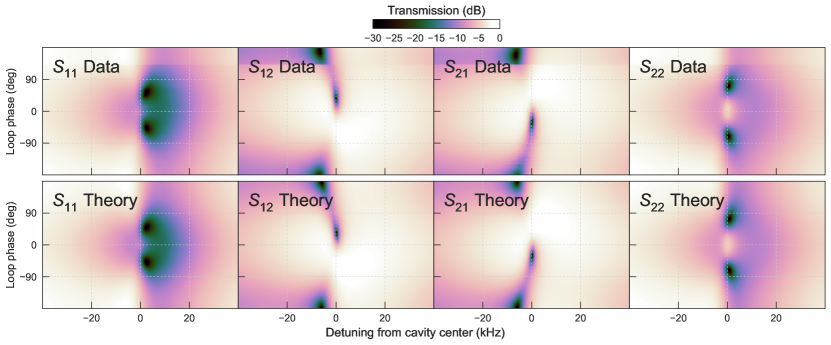
Figure 3(b) shows the measured transmission from cavity 2 to cavity 1 (left) and from 1 to 2 (right) at two loop phases for a particular drive configuration found from the tuning process. On cavity resonance at degrees (solid blue), we see high transmission (insertion loss of dB) from cavity 2 to cavity 1 but low transmission (isolation of dB) from cavity 1 to 2 over a frequency band of kHz. At degrees (dashed green), the behavior reverses. We collect data at many loop phases, shown in Fig. 3(c) with horizontal lines indicating the cuts shown in Fig. 3(b). We fit the data to the expanded coupled-mode model using a two-dimensional nonlinear least-squares fit, the result of which is shown in Fig. 3(d), demonstrating excellent agreement with the data. Mapping our expanded model onto the four-mode system gives the effective system parameters. The effective mechanical linewidths are kHz and kHz, in agreement with the nonreciprocal bandwidth of 5 kHz. The four effective cooperativities are , where the notation indicates the cooperativity coupling cavity to effective mechanical mode .
While the loop phase of degrees gives good balance between the goals of high reverse isolation and low insertion loss, other loop phases can be maximize these metrics individually. For the drive configuration shown here, the insertion loss can be as low as 1.16 dB ( efficiency) at degrees at the expense of reducing reverse isolation to 9.2 dB. Alternatively, the reverse isolation can be tuned arbitrarily high near degrees at the expense of slightly increasing the insertion loss. In our system, we observe isolation at a single frequency as high 49 dB with corresponding insertion loss of 1.9 dB.
An ideal isolator for applications to signal processing and quantum information would be both efficient and noiseless. To characterize the noise properties of the device while the four drives are on, we measure the noise spectrum at the cavity outputs. In Fig. 4(a), we show the signal flow diagrams corresponding to the ideal scattering matrix (Eq. 1) at the two optimal loop phases. Importantly, the power input to the mechanical modes (namely, thermal noise) should appear at the isolated cavity but not the other cavity. The measured noise spectra shown in Fig. 4(b) demonstrate this behavior. At the loop phase that isolates cavity 1 from cavity 2 (near degrees in green), a noise peak of about 7 photons appears at cavity 1. The behavior reverses at the opposite loop phase. Data as a function of frequency and loop phase are shown in Fig. 4(c), with horizontal lines indicating the cuts used in Fig. 4(b).
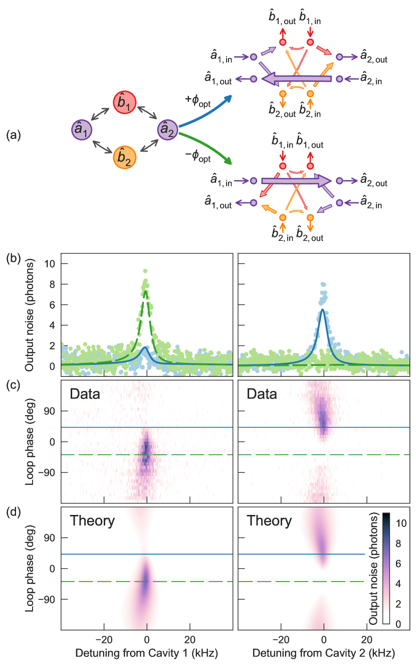
We fit the noise spectra to our expanded model using the parameters determined from the driven response fit as fixed inputs (Fig. 4d). The only remaining free parameters are the thermal occupation numbers of the two mechanical environments, and . Equation (1) predicts the output noise of the isolated port to be the average of these two occupation numbers. In our system, off-resonant interactions naturally damp and cool the mechanical modes, yielding lower effective occupation numbers of the environment , measured to be and . The occupancies of the mechanical modes themselves depend on the loop phase, with their maxima and minima occurring at and degrees, respectively. From the fit to the data in Fig. 4, we infer that these mechanical occupancies range from 0.13 to 0.60 phonons in mode one and from 1.5 to 3.7 phonons in mode two. Future implementations of the optomechanical isolator could reduce the output noise by starting with lower effective mechanical environment occupation numbers, for example by introducing additional beam-splitter interactions to further damp and cool the mechanical modes outside the nonreciprocal loop.
The device reported here represents a significant advancement of nonreciprocal technology using optomechanical resources. We have derived closed-form expressions for the optimal drive conditions required for ideal isolation and have experimentally implemented them in a microwave optomechanical circuit. We have fully characterized the nonreciprocal performance of the device, both in the scattering parameters and the output noise. The ability to reach high optomechanical cooperativity combined with the use of an expanded coupled-mode model to fit the data and tune parameters has allowed us to improve upon crucial metrics of isolation, approaching the stringent requirements of quantum information processing. In addition, the quantitative agreement between data and theory shown here will be crucial for further optimizing performance within experimental constraints as well as developing more complex multimode systems.
Looking forward, the scheme we have employed can be straightforwardly applied to other optomechanical systems, including those at optical frequencies. The addition of optomechanical systems to the nonreciprocal parametric toolbox offers the new possibility to directionally route acoustic signals, and could enable nonreciprocal microwave-to-optical transduction. Because the theory of the device applies generally beyond optomechanical systems, the nonreciprocal behavior described here could also be explored in other parametric systems including microwave resonators coupled through Josephson junctions. Parametric nonreciprocity is a promising and quickly developing field, which may soon enable previously unattainable efficiencies for both measurement and control of classical and quantum systems.
Note
While preparing this manuscript, we became aware of another work using a similar method to demonstrate optomechanical nonreciprocity BernierTothKoottandavidaEtAl2016 .
Official contribution of the National Institute of Standards and Technology; not subject to copyright in the United States.
I Supplementary Information
I.1 General theory of a four-mode isolator
We will use the language and notation established in Ref. LecocqRanzani2017 to analyze a four-mode isolator. We characterize each mode, regardless of its physical manifestation, by a natural frequency , a linewidth , and a signal frequency set by the drive frequencies and weak probe input frequency. Modes and can be coupled with a complex coupling rate . We describe the four-mode loop configuration by a mode-coupling matrix,
| (2) |
where is the normalized complex detuning of mode , and is the normalized complex coupling strength between modes and .111Note that the definition of differs from that in Ref. LecocqRanzani2017 by a factor of two to coincide with the conventional definition of in the optomechanics literature. In our system, modes 1 and 2 are microwave cavities and modes 3 and 4 are mechanical. The normalized magnitude of susceptibility for mode plotted in Fig. 1 is . To clarify the analytic results, we assume and ; that is, each mechanical mode is equally coupled to both cavity modes. We also put an explicit on for the loop phase, so that the mode-coupling matrix becomes
| (3) |
The scattering matrix is found from , where . We require nonreciprocity to occur at the cavity resonance frequencies. This demand lets us set . On resonance, the real parts of the mechanical detunings are equal to the detunings of the drives from the red sidebands: , where is a normalized detuning such that the drive frequency is for and .
We first require the device impedance matching () on resonance. In the high-cooperativity and limits, impedance matching results in the condition and gives the optimal detuning as
| (4) |
where is the cooperativity associated with the optomechanical interaction involving mode .
We parameterize isolation in the system by the transmission difference . At the optimal drive detuning,
| (5) |
Maximizing transmission difference over phase, we find the optimal loop phase , with which the transmission difference becomes
| (6) |
At high cooperativity, maximizing this function yields with corrections at order , simplifying the transmission difference to . With these conditions applied, the scattering matrix at high cooperativity and becomes
| (7) |
Choosing the opposite phase transposes the above matrix. Note that, while the qualitative behavior remains the same, at low cooperativities the optimizations discussed above are not exact. In analyzing the experimental data, we therefore use numerical maximization of the exact difference function to decide how to update the drive parameters.
To find the bandwidth of nonreciprocity, we calculate the transmission difference as a function of the detuning from the cavity centers with the approximation that the cavity widths are much larger than the mechanical widths. With the above optimizations for drive detunings, loop phase, and cooperativities, the result is
| (8) |
where . The above shows that in the high cooperativity limit the bandwidth of nonreciprocity is independent of cooperativity and equal to
| (9) |
I.2 Off-resonant damping and expanded coupled-mode theory
Due to the off-resonant coupling terms discussed in the text, each mechanical mode can respond to all four drives. To be able to predict the effect of changing the drive powers and frequencies, these extra interactions must be included in the model. Expanding our mode basis allows us to fit the experimental data using the intrinsic mechanical properties and also predict the needed drive parameters to obtain optimal performance.
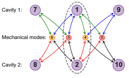
The expanded mode basis needed, diagrammed in Fig. 5, comes directly from the coupled equations of motion. In the diagram, like-colored arrows indicate interactions driven by the same microwave drive. Modes 1 through 4 are the four modes appearing in the simplified four-mode model discussed above. Modes 5 through 10 are auxiliary modes evaluated at the relevant off-resonant frequencies determined by the drives. For example, the signal frequency of mode 7 is , while that of mode 8 is . As our analysis takes place in the Fourier domain, each of these distinct coupled frequencies acts as another mode, even if it resides in the same physical oscillator as another mode. For this reason, modes 1, 7, and 9 share the resonance frequency and linewidth of cavity 1. Likewise for modes 2, 8, and 10 in cavity 2, and for the mechanical mode pairs {3, 5} and {4, 6}.
A note is needed to justify the presence of the off-resonant mechanical modes 5 and 6. In general, these extra modes are needed to maintain common linewidths and frequencies of all the auxiliary cavity modes. This effect is typically negligible in optomechanics because the cavities are so much wider than the mechanical modes. Another reason for including modes 5 and 6, however, is to be able to model the scattering parameters over wide spans that include both resonant and off-resonant structure. We therefore include the off-resonant mechanical terms to able to fit wide scans of scattering parameters.
In total, these considerations lead to our system of ten modes that quantitatively accounts for the off-resonant damping. Notably, we ignore all amplification processes occurring at the blue sidebands. This is a reasonable approximation because the damping effects from these terms are smaller by a factor of .
We have justified the need for an expanded model and shown how to find the signal frequencies of the modes. The last part needed before calculating the scattering matrix are the couplings involving the auxiliary modes. These are found by relating all 16 couplings to the 4 original couplings by multiplying by ratios of vacuum optomechanical coupling rates and intrinsic mechanical linewidths.
With the mode-coupling matrix fully determined, we proceed to calculate the scattering matrix as above. We use this expanded model for the scattering parameters to fit the data shown in the text and to predict the needed drive parameters to maximize the transmission difference function. Figure 6 shows the full fit including the reflection coefficients.
The ten-mode graph can be reduced to obtain an effective four-mode graph. By allowing the inputs for the auxiliary modes to be exactly zero, one can derive the effective mode-coupling matrix describing the reduced system. This reduction procedure is a classical approximation, so care must taken in its application to quantum noise calculations. In general, to reduce mode from the matrix , we perform the transformation
| (10) |
which results in a new matrix with one less dimension. Reducing each auxiliary mode in turn results in the effective four-mode model. Incidentally, the mode reduction formula encodes the meaning of the rotating wave approximation in Fourier space; if the correction to element is negligible for all signal frequencies of interest, the dynamics of mode can be safely ignored.
I.3 Calculation and calibration of output noise
Here we calculate a model for the output noise given the () scatting matrix calculated above. We start with the system output amplitude, then model the amplifier chain and the spectrum analyzer.
The output amplitude for mode in terms of the input amplitudes is
| (11) |
The output amplitude is then amplified, which we model as a transformation to another mode operator, , by
| (12) |
where is the gain at port , and is an input creation operator used to model the amplifier’s added noise. When the mode is fed into the spectrum analyzer, the measured noise power spectrum is ClerkDevoretGirvinEtAl2010
| (13) |
Taking the large gain limit (so that ), and using input correlators for a thermal state with occupancy , we find
| (14) |
where is the noise from the amplifier, and is the thermal occupation number for the input field at port . We measure in units of W Hz-1. Knowing the system gain and added noise allows us to convert the spectrum to units of output photons from the device. When the set of (and possibly the ) are the only fit parameters, the model is linear and can therefore be fit to the data using linear least-squares fitting methods. The third term in the above equation is what we refer to as the output noise of the device. We measure the amplification noise at the two cavity frequencies to be and .
We calibrate the output noise by heating the cryostat to 100 mK and measuring single drive optomechanical spectra TeufelDonnerLiEtAl2011 . This process yields the system gain, system added noise, and the four vacuum optomechanical coupling rates, which are found for each cavity-mechanical mode pair to be Hz, where is the vacuum coupling rate for the th cavity and the th mechanical mode.
References
- (1) D. Jalas, A. Petrov, M. Eich, W. Freude, S. Fan, Z. Yu, R. Baets, M. Popović, A. Melloni, J. D. Joannopoulos, M. Vanwolleghem, C. R. Doerr, and H. Renner. What is — and what is not — an optical isolator. Nat. Photonics, 7(8):579–582, 2013.
- (2) H. J. Kimble. The quantum internet. Nature, 453(7198):1023–1030, 2008.
- (3) D. Polder. On the theory of ferromagnetic resonance. Physica, 15(1-2):253–255, 1949.
- (4) C. L. Hogan. The ferromagnetic Faraday effect at microwave frequencies and its applications. Bell Sys. Tech. J., 31(1):1–31, 1952.
- (5) L. J. Aplet and J. W. Carson. A Faraday effect optical isolator. Appl. Opt., 3(4):544, 1964.
- (6) N. Roch, E. Flurin, F. Nguyen, P. Morfin, P. Campagne-Ibarcq, M. H. Devoret, and B. Huard. Widely tunable, nondegenerate three-wave mixing microwave device operating near the quantum limit. Phys. Rev. Lett., 108(14), 2012.
- (7) W. F. Kindel, M. D. Schroer, and K. W. Lehnert. Generation and efficient measurement of single photons from fixed-frequency superconducting qubits. Phys. Rev. A, 93(3), 2016.
- (8) J. B. Clark, F. Lecocq, R. W. Simmonds, J. Aumentado, and J. D. Teufel. Observation of strong radiation pressure forces from squeezed light on a mechanical oscillator. Nat. Phys., 12(7):683–687, 2016.
- (9) N. A. Estep, D. L. Sounas, J. Soric, and A. Alù. Magnetic-free non-reciprocity and isolation based on parametrically modulated coupled-resonator loops. Nat. Phys., 10(12):923–927, 2014.
- (10) A. Kamal, A. Roy, J. Clarke, and M. H. Devoret. Asymmetric frequency conversion in nonlinear systems driven by a biharmonic pump. Phys. Rev. Lett., 113(24), 2014.
- (11) B. Abdo, K. Sliwa, S. Shankar, M. Hatridge, L. Frunzio, R. Schoelkopf, and M. Devoret. Josephson directional amplifier for quantum measurement of superconducting circuits. Phys. Rev. Lett., 112(16), 2014.
- (12) J. Kerckhoff, K. Lalumière, B. J. Chapman, A. Blais, and K. W. Lehnert. On-chip superconducting microwave circulator from synthetic rotation. Phys. Rev. Appl, 4(3), 2015.
- (13) K. M. Sliwa, M. Hatridge, A. Narla, S. Shankar, L. Frunzio, R. J. Schoelkopf, and M. H. Devoret. Reconfigurable Josephson circulator/directional amplifier. Phys. Rev. X, 5(4), 2015.
- (14) C. Macklin, K. O'Brien, D. Hover, M. E. Schwartz, V. Bolkhovsky, X. Zhang, W. D. Oliver, and I. Siddiqi. A near-quantum-limited Josephson traveling-wave parametric amplifier. Science, 350(6258):307–310, 2015.
- (15) A. Metelmann and A. A. Clerk. Nonreciprocal photon transmission and amplification via reservoir engineering. Phys. Rev. X, 5(2), 2015.
- (16) M. S. Kang, A. Butsch, and P. St. J. Russell. Reconfigurable light-driven opto-acoustic isolators in photonic crystal fibre. Nat. Photonics, 5(9):549–553, 2011.
- (17) L. Ranzani and J. Aumentado. Graph-based analysis of nonreciprocity in coupled-mode systems. New J. Phys., 17, 2015.
- (18) B. Abdo, K. Sliwa, L. Frunzio, and M. Devoret. Directional amplification with a Josephson circuit. Phys. Rev. X, 3(3), 2013.
- (19) A. Kamal, J. Clarke, and M. H. Devoret. Noiseless non-reciprocity in a parametric active device. Nat. Phys., 7(4):311–315, 2011.
- (20) F. Lecocq, L. Ranzani, G. A. Peterson, K. Cicak, R. W. Simmonds, J. D. Teufel, and J. Aumentado. Nonreciprocal microwave signal processing with a field-programmable Josephson amplifier. Phys. Rev. Appl, 7(024028), 2017.
- (21) M. Hafezi and P. Rabl. Optomechanically induced non-reciprocity in microring resonators. Opt. Express, 20(7):7672, 2012.
- (22) X.-W. Xu, Y. Li, A.-X. Chen, and Y.-X. Liu. Nonreciprocal conversion between microwave and optical photons in electro-optomechanical systems. Phys. Rev. A, 93(2), 2016.
- (23) Z. Shen, Y.-L. Zhang, Y. Chen, C.-L. Zou, Y.-F. Xiao, X.-B. Zou, F.-W. Sun, G.-C. Guo, and C.-H. Dong. Experimental realization of optomechanically induced non-reciprocity. Nature Photonics, 10(10):657–661, 2016.
- (24) F. Ruesink, M. Miri, A. Alù, and E. Verhagen. Nonreciprocity and magnetic-free isolation based on optomechanical interactions. Nat. Commun., 7:13662, 2016.
- (25) K. Fang, J. Luo, A. Metelmann, M. H. Matheny, F. Marquardt, A. A. Clerk, and O. Painter. Generalized non-reciprocity in an optomechanical circuit via synthetic magnetism and reservoir engineering. Nat. Phys., 2017.
- (26) F. Lecocq, J. B. Clark, R. W. Simmonds, J. Aumentado, and J. D. Teufel. Mechanically mediated microwave frequency conversion in the quantum regime. Phys. Rev. Lett., 116(4), 2016.
- (27) Y. Liu, M. Davanço, V. Aksyuk, and K. Srinivasan. Electromagnetically induced transparency and wideband wavelength conversion in silicon nitride microdisk optomechanical resonators. Phys. Rev. Lett., 110(22), 2013.
- (28) Q. Li, M. Davanço, and K. Srinivasan. Efficient and low-noise single-photon-level frequency conversion interfaces using silicon nanophotonics. Nat. Photonics, 10(6):406–414, 2016.
- (29) R. W. Andrews, R. W. Peterson, T. P. Purdy, K. Cicak, R. W. Simmonds, C. A. Regal, and K. W. Lehnert. Bidirectional and efficient conversion between microwave and optical light. Nat. Phys., 10:321–326, 2014.
- (30) M. Aspelmeyer, T. J. Kippenberg, and F. Marquardt. Cavity optomechanics. Rev. Mod. Phys., 86(4):1391–1452, 2014.
- (31) W. H. Louisell. Coupled mode and parametric electronics. Wiley, New York, 1960.
- (32) C. W. Gardiner and M. J. Collett. Input and output in damped quantum system: Quantum stochastic differential equations and the master equation. Phys. Rev. A, 31(6), 1985.
- (33) K. Cicak, D. Li, J. A. Strong, M. S. Allman, F. Altomare, A. J. Sirois, J. D. Whittaker, J. D. Teufel, and R. W. Simmonds. Low-loss superconducting resonant circuits using vacuum-gap-based microwave components. Appl. Phys. Lett., 96(9):093502, 2010.
- (34) J. D. Teufel, Dale Li, M. S. Allman, K. Cicak, A. J. Sirois, J. D. Whittaker, and R. W. Simmonds. Circuit cavity electromechanics in the strong-coupling regime. Nature, 471(7337):204–208, 2011.
- (35) F. Lecocq, J. D. Teufel, J. Aumentado, and R. W. Simmonds. Resolving the vacuum fluctuations of an optomechanical system using an artificial atom. Nat. Phys., 11(8):635–639, 2015.
- (36) N. R. Bernier, L. D. Tóth, A. Koottandavida, A. Nunnenkamp, A. K. Feofanov, and T. J. Kippenberg. Nonreciprocal reconfigurable microwave optomechanical circuit, 2016, arXiv:1612.08223.
- (37) A. A. Clerk, M. H. Devoret, S. M. Girvin, F. Marquardt, and R. J. Schoelkopf. Introduction to quantum noise, measurement, and amplification. Rev. Mod. Phys., 82(2):1155–1208, 2010.
- (38) J. D. Teufel, T. Donner, D. Li, J. W. Harlow, M. S. Allman, K. Cicak, A. J. Sirois, J. D. Whittaker, K. W. Lehnert, and R. W. Simmonds. Sideband cooling of micromechanical motion to the quantum ground state. Nature, 475(7356):359–363, 2011.