Design, fabrication and high-gradient tests of X-band choke-mode structures ††thanks: Work supported by the National Natural Science Foundation of China (Grant No. 11135004).
Abstract
Two standing-wave single-cell choke-mode damped structures with different choke dimensions which worked at 11.424 GHz were designed, manufactured and tuned by accelerator group in Tsinghua University. High power test was carried out to study choke-mode structure’s properties in high gradient and related breakdown phenomenon. A single-cell structure without choke which almost has the same inner dimension as choke-mode structure was also tested as a comparison to study how the choke affects high-gradient properties. In this paper, we report on the latest status of the high power test, including various observations and the experimental results.
1 INTRODUCTION
As an alternative design for CLIC main accelerating structures, X-band choke-mode structures had been studied under the collaboration between Tsinghua University, CERN and KEK [1, 2, 3, 4]. Three X-band single-cell standing-wave structures including two choke-mode structures and one reference structure without choke were designed, fabricated, assembled, and tuned by Tsinghua University. The high power test, aiming at studying the high-gradient properties of X-band choke-mode structure, were carried out at Nextef [5] facility in KEK. One of the choke-mode structures was cut into three pieces for inner surface observation after the high power test. Below we report the main results of the test. Observations from post-mortem are also presented.
2 overview OF THE SINGLE-CELL STRUCTURES
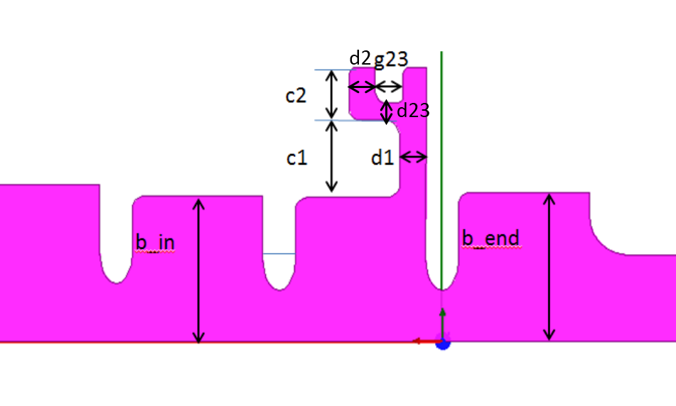
The single-cell standing-wave structure consists of three parts: the input coupler cell, the high-gradient middle cell(s), and the end cell [6]. Three single-cell standing-wave structures including two choke-mode designs and one reference design were proposed by Tsinghua University. Geometry of the choke-mode structure is shown in Fig. 1. The names of the single-cell structures are derived from the manufacturer’s name plus structure’s type and key geometry. An example of a single-cell structure name is: THU-CHK-D1.26-G1.68. Here THU is the manufacturer and CHK is the structure’s type. D1.26 is the d23 dimension in mm and G1.68 is the d1 dimension in mm, as shown in Fig. 1. The single-cell structures we designed and tested are: THU-CHK-D1.26-G1.68, THU-CHK-D1.26-G2.1 and THU-REF111Note the nomenclature here is different from that in [4]. Dimension of d23 shown in Fig. 1 is added in the structure’s name.. The details of RF design can be found in [4].
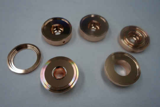
The mechanical design of single-cell choke-mode structure was made of 6 disks, as shown in Fig. 2. The middle cell with choke was achieved by two disks together. All of these disks were manufactured by turning because of the symmetrical design of choke-mode structure.
The disks were first cleaned and etched by the internal procedures based on GLC fabricating technology and then bonded. The contact areas of each choke-mode structure disks are not consistent vertically. This may cause deformations during the bonding. A choke-mode structure prototype was fabricated for diffusion bonding test to check the bonding quality. During the bonding test, the prototype was cut into halves for bonding contact area check. After completion of the successful bonding test, the individual parts of the single-cell structures were diffusion bonded in a hydrogen furnace at Tsinghua University. Operating frequency was tuned to 11.424 GHz at the working temperature of 30 ∘C which is the standard cooling water temperature at Nextef. The structures were vacuum baked at 500 ∘C for 5 days. The structures were kept under vacuum after baking by sealing with a valve and then shipped to KEK also under vacuum. Rf measurement results at KEK kept consistent with that tested in Tsinghua University.
3 High power test
High power test was carried out after the structure was installed in Shield-B [5] of Nextef at KEK. THU-CHK-D1.26-G1.68 was first tested followed by THU-CHK-D1.26-G2.1 and THU-REF. Nextef, which stands for New X-band Test Facility of KEK, was founded in 2006 as a reassembled facility of GLCTA [7, 8] as a 100 MW high power station for X-band accelerating structure study. Shield-B is aiming at basic high-gradient study by testing single-cell structures [9].
3.1 Test stand
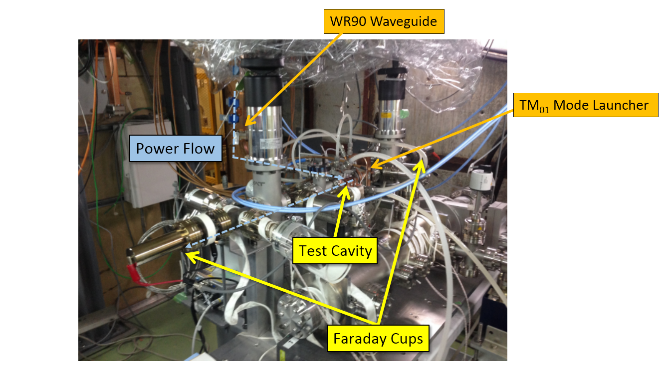
The experimental setup for high-gradient tests is shown in Fig. 3. RF power was transferred to Shield-B via WR90 waveguide and circular low-loss wave guide and then fed into the cavity from the TM01 mode launcher seen in the right side. The reflection rf signal and the dark current signals were monitored pulse-by-pulse during the operation for breakdown detection. Once breakdown occurred, we stopped the next rf pulse and waited for several tens of seconds before the next rf pulse. Typically, the operation would reduce the rf power by about 5% and ramp the power again by increasing 0.2 MW in 20 seconds.
3.2 RF waveforms
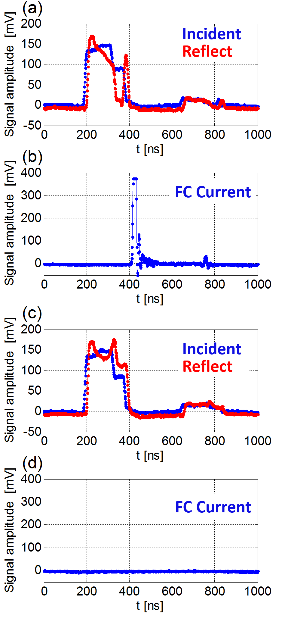
In order to have a constant high field in the test cell as long as possible, we shaped the rf pulse into double steps as shown in Fig. 4(a). In the first step for 100 ns, we charged RF energy in the test cavity (charging step). In the second step for 100 to 300 ns (maintaining step), the rf power was decreased to approximately 36% of that in the charging step [9]. The width of maintaining step was changed in different pulse width operations. The current signal collected by the Faraday cup is shown in Fig. 4(b).

3.3 Experimental results
The summary of the conditioning history of THU-CHK-D1.26-G1.68 is shown in Fig. 5. The blue, green and red points represent the Eacc, the pulse width of rf power and the accumulated number of breakdowns, as a function of elapsed hours respectively. The Eacc value was recorded at every interlock event. The dots which fall below the envelope of Eacc correspond to interlocks in the power ramping stage after previous breakdown. Rf power could not be further increased after 100 hours in 100 ns pulse width operation due to continuous breakdowns. Same phenomenon happened at longer pulse width operation. The maximum gradient obtained in the test was 75 MV/m as shown in Fig. 5.

Two types of breakdowns, which were accompanied with and without current flash, were observed in the high power test. Waveforms of these two breakdowns are shown in Fig. 6. Breakdowns were accompanied with the current flash into the Faraday cup during the initial ramping stage. After initial ramping, few current flash breakdowns were observed in the detected events. As the Faraday cups were located at the end of the pipe axis, the electrons emitted from the choke breakdown area were not easily collected. It was speculated that breakdowns with current flash happened in the cylinder cavity while breakdowns without current flash happened in the choke. Frequent breakdowns in the choke during the high-gradient test were assumed to be the main limitation of obtaining higher gradient as shown in Fig. 5. This speculation was verified in the post-mortem observation. This will be discussed in the next section.
4 Post-mortem observation
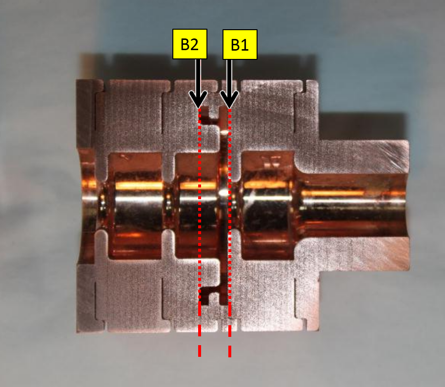
THU-CHK-D1.26-G1.68 was cut after the high-gradient test was finished. The structure was cut along radial direction twice as shown in Fig. 7. Cutting along radial direction allowed microscopy imaging of the choke surfuce which was speculated as frequent breakdown sites. The surfaces of the irises and cylinder cavity are very clean while the surfaces of the choke groove are very rough with naked eye observation. The structure was then examined with a microscope. The microscopy’s model is KEYENCE VE-8800.
Ten points were chosen for inner surface inspections as show in Fig. 8.
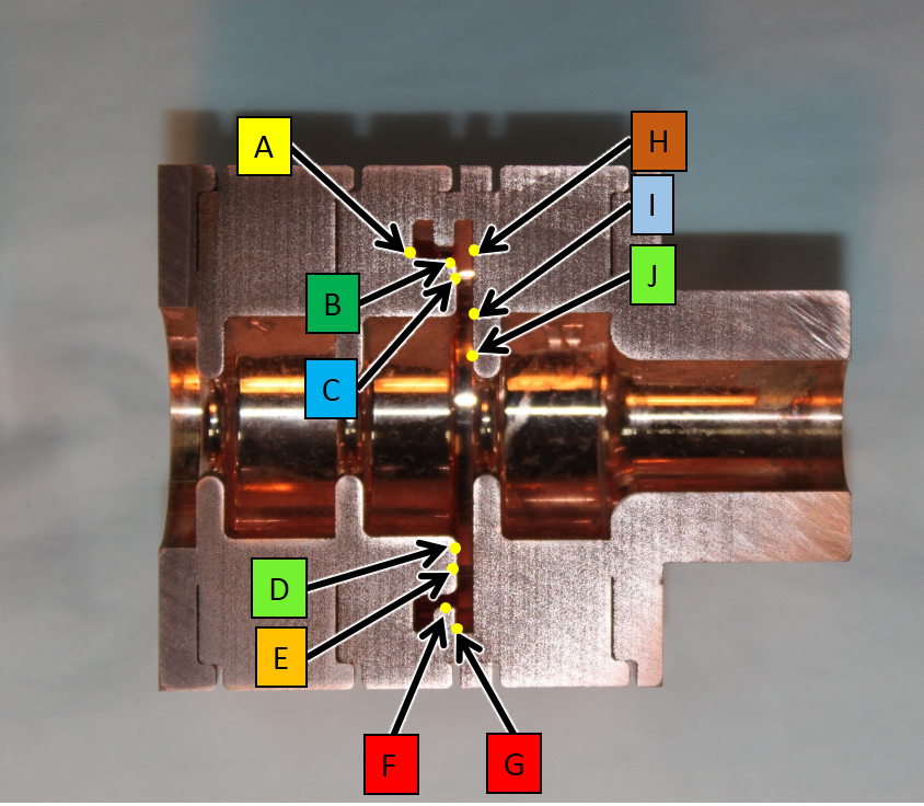
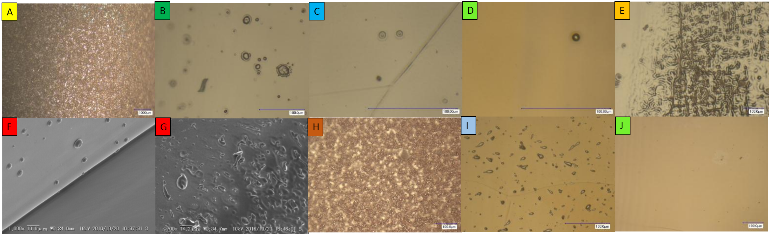
The inner surface observation results are shown in Fig. 9. The areas of cylinder cavity and irises are clean as shown in point D and J. This indicates that few breakdowns occurred in these areas. Microscopy imaging of piont B, E, F, G, H and I showed damage such as "craters", small "protrusions" and "speckles". Point B and F showed significantly more damage than the other points. The damage at point E, G, H and I is speculated as melting copper sputtered from the choke area. Therefore, d2 area shown in Fig. 1 has a high breakdown rate.
5 status and plan
The high-gradient tests of three structures have been finished in 2017.1. However, the data of the rest two structures are still under analyzing. In order to achieve higher gradient in choke-mode structure, we have designed new single-cell choke-mode structures with larger d2. New structures are under fabrication for the high-gradient test.
6 Conclusion
Two standing-wave single-cell choke-mode damped structures as well as one reference structure have been successfully designed and fabricated at Tsinghua University. High power tests were carried out at the Nextef facility in KEK and the test demonstrated that the present choke-mode structure can operate at a highest gradient of 75 MV/m. Two types of breakdowns, which were accompanied with and without current flash, were observed in the test. The former one was speculated to be the breakdown occurred in the iris and cylinder cavity area while the latter one was speculated to be located in the choke. Post-mortem of THU-CHK-D1.26-G1.68 verified this speculation and indicated that d2 area of the choke is the critical limitation of obtaining higher gradient. The present d2 with dimension of 1.26 mm will cause continuous breakdowns around 75 MV/m.
7 acknowledgement
This work was supported by the National Natural Science Foundation of China (Grant No. 11135004). The experimental program had also been supported as one of the collaborations of the CLIC under the agreement between Tsinghua University and CLIC and that, ICA-JP-0103, between KEK and CERN. The authors thank those of KEK electron-positron injector group for supporting the long-term operation.
References
- [1] A. Grudiev and W. Wuensch, “Design of the CLIC main linac accelerating structure for CLIC conceptual design report”, in Proc. LINAC2010, Kyoto, Japan, 2010, pp. 211–213.
- [2] T. Shintake, “The choke mode cavity”, Jpn. J. Appl. Phys., vol. 31, L1567, 1992.
- [3] H. Zha et al., “Choke-mode damped structure design for the compact linear collider main linac”, Phys. Rev. ST Accel. Beams, vol. 15, p. 122003, 2012.
- [4] X. W. Wu, J. Shi, H. Zha, H. Chen et al., “High power test of X-band single cell HOM-free choke-mode damped accelerating structure made by Tsinghua University”, in Proc. IPAC’16, Busan, Korea, 2016, pp. 3881–3883.
- [5] S. Matsumoto, T. Abe, Y. Higashi, T. Higo, and Y. Du et al., “High gradient test at Nextef and high-power long-term operation of devices”, Nucl. Instr. Meth., vol. 657, pp. 160–167, 2011.
- [6] V. A. Dolgashev et al., “Status of high power tests of normal conducting single-cell structures”, in Proc. PAC’05, Genoa, Italy, 2005, pp. 595–599.
- [7] S. Matsumoto, M. Akemoto, S. Fukuda, T. Higo et al., "Nextef : 100MW X-band test facility in KEK", in Proc. EPAC’08, Genoa, Italy, 2008, pp. 2740–2742.
- [8] S. Fukuda et al., "R & D plan of rf source in KEK GLCTA", in Proc. PASJ2004, Funabashi, Japan, 2004, pp. 75–77 (in japanese).
- [9] T. Abe, Y. Arakida, T. Higo, S. Matsumoto, T. Takatomi, X. W. Wu, J. Shi et al., "High-gradient testing of single-cell test cavities at KEK/ Nextef", in Proc. PASJ2016, Chiba, Japan, 20016, pp. 348–352.