Terahertz detection using mechanical resonators based on 2D materials
Abstract
We have investigated a THz detection scheme based on mixing of electrical signals in a voltage-dependent capacitance made out of suspended graphene. We have analyzed both coherent and incoherent detection regimes and compared their performance with the state of the art. Using a high-amplitude local oscillator, we anticipate potential for quantum limited detection in the coherent mode. The sensitivity stems from the extraordinary mechanical and electrical properties of atomically thin graphene or graphene-related 2D materials.
pacs:
PACS numbers:I Introduction
Interest in THz detection and imaging technologies is traditionally motivated by astronomy and more recently also by a growing demand for new solutions for enhancing public security. Passive THz imaging using cryogenic sensor arrays has been successful in fulfilling this demand. At present, incoherent detectors based on transition edge sensors and coherent detectors typically based on SIS mixers have applications in astronomical imaging Holland et al. (2013); Baryshev et al. (2015). Security applications using a few different approaches have been demonstrated as well Grossman et al. (2010); Heinz et al. (2011); Luukanen et al. (2012). New solutions with enhanced sensitivity, increased operating temperature, or an increased level of integration are being developed constantly Timofeev et al. (2017). Additional possibilities to such quest are provided by THz detectors based on micro- (MEMS) or nanoelectromechanical (NEMS) systems, especially those employing novel 2D materials Ferrari et al. (2015) such as graphene. Due to the extraordinary mechanical properties, atomically thin NEMS might yield a significant sensitivity improvement in the operation of mechanical radiation detection devices.
THz detection using graphene has aroused considerable interest Vicarelli et al. (2012); Sensale-Rodriguez et al. (2012); Mittendorff et al. (2013); Muraviev et al. (2013); Cai et al. (2014); Wang et al. (2014). Previous work has taken advantage of graphene’s linear band structure and the low heat capacity of single-layer graphene. THz detection has been done via a plasmonic mechanism Muraviev et al. (2013), by bolometric detection Mittendorff et al. (2013), and by noise thermometry Wang et al. (2014). A recent experiment Cai et al. (2014) with graphene FET with dissimilar contact metals reached noise equivalent power (NEP) around 20 pW/Hz1/2 operating at room temperature. Svintsov et. al. Svintsov et al. (2014) have proposed a scheme with suspended graphene FET, where they take advantage of the plasma resonance that naturally occurs at THz frequencies for short graphene devices. The results so far have remained inferior to the current state-of-the-art bolometers based on superconducting detectors, which reach noise equivalent powers (NEP) around 10 fW/Hz1/2 in the 0.2 – 1.0 THz band at K Penttilä et al. (2006) and below 1 aW/Hz1/2 at 20 mK de Visser et al. (2014). For coherent detectors the relevant figure of merit is the receiver noise temperature . For SIS mixer receiver noise temperatures a few times above the quantum limit (with and denoting the Planck constant and the Boltzmann constant, respectively) have been reported Baryshev et al. (2015). Ultra-low-noise. coherent receiver operation of graphene at THz is largely unexplored, albeit graphene based integrated subharmonic mixer circuits have been demonstrated at 200-300 GHz frequencies Antuña et al. (2015); Zhang et al. (2016).
Here we propose an original scheme of detecting THz radiation using antenna-coupled mechanical resonators based on atomically thin two-dimensional materials. As the performance of this scheme relies heavily on the properties of the mechanical detector element, we have chosen to employ graphene in our device. Graphene shows great promise for superior sensitivity owing to its high Young’s modulus TPa and extremely light weight. For optimized radiation detection, the mechanical capacitance has to be matched to a measurement system which is done by employing an electromagnetic cavity (or lumped element circuit). Consequently, our mechanical THz detection setting resembles an optomechanical system, but has a different type of coupling between electrical signals and the mechanical motion. As in microwave optomechanics, our setup requires superconducting elements to deliver sufficiently large quality factors, which facilitate our detectors to reach the quantum limit of sensitivity.

II Power resolution
We analyze a system where a mechanical resonator is coupled to a THz regime antenna. The signal picked up by the antenna drives the mechanical resonator, and the resulting mechanical vibrations are detected. In our analysis, we don’t consider the detection of mechanical motion - we just assume that it can be done down to the oscillation amplitude limit set by thermal excitation. Demonstration of detection of such thermally driven motion down to 50 mK has been presented, for example, in Ref. Song et al. (2014) in a bilayer graphene NEMS resonator using cavity optomechanics.
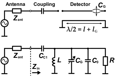
Dipole or log spiral antennas can be designed with real impedance of several tens of ohms, the value of which can be matched to a transmission line resonator with a capacitance Cc by requiring Zin = Zant (Fig. 1). In the transmission line case, the input impedance is given by
| (1) |
where Qe and Z0 are the quality factor of the resonator and the characteristic impedance, respectively, and is the angular frequency of the electromagnetic radiation. In Fig. 1a the geometry is such that the mechanical resonator covers only a fraction of the cavity length at the end of the microwave (THz) resonator. However, it is also possible in principle that the well-conducting mechanical resonator material forms the electrical cavity by itself. Such a geometry would be optimal for detection sensitivity (see below).
The antenna can also be matched to a mechanical resonator whose dimensions are smaller than the wavelength, in which case the matching is done by a separate, lumped element LC structure with equivalent performance. In the lumped element case, the matching is done by setting equal to the antenna impedance, i.e. acts as the characteristic impedance of a corresponding distributed resonator.
The voltage amplitude of the standing wave induced by a signal can be expressed as
| (2) |
where the capacitance includes the sensor capacitance and the equivalent capacitance of the strip line (or coplanar line) of the electrical resonator. The mechanical resonator then feels an eletrostatic force according to , where d is the vacuum gap between the graphene element and its counterelectrode (ground). Using the two equations above, the force responsivity F/Psig becomes
| (3) |
In the ideal case, when electrical cavity is formed by the mechanical resonator, the capacitive shunting factor reducing the sensitivity becomes equal to one, while for the setting in Fig. 1a it equals to ().
The power resolution of the detector is ultimately limited by mechanical thermal noise. The mechanical noise can be expressed using the fluctuation-dissipation theorem as where T is the temperature of the detector element (phonon temperature), and denotes the damping rate of the mechanical resonator; at low temperatures electronic temperature may deviate substantially from phonon temperature due to weak electron-phonon coupling Laitinen et al. (2014). By replacing the decay rate , the force fluctuations can be written as , where is the mechanical angular frequency, m denotes the resonator mass 111We neglect here the mechanical mode shape which could lower the effective mass down to ., and Qm is the mechanical quality factor. Noise equivalent power is then given by , which leads to
| (4) |
The above equation works generally for any antenna matched MEMS system, regardless of the design details. Thus, it can be used to estimate performance of the system, if the characteristics of the electrical and mechanical resonators are known. The only requirement is that the resonator motion can be measured at the thermal motion level. Although the detector can work at room temperature, lowering the temperature directly improves sensitivity by reducing thermal noise as shown in Eq. (4), and typically the values of mechanical graphene resonators are significantly larger at cryogenic temperatures.
A substantial amount of experiments have been performed on graphene mechanical resonators Bunch et al. (2007); Chen et al. (2009); Song et al. (2012, 2014); Weber et al. (2016); Singh et al. (2014) and hence we can reliably estimate the expected performance. For a realistic case study, we adopt the experimental parameters for a bilayer graphene resonator from Ref. Song et al., 2014, i.e. m/2 = 24 MHz, vacuum gap = 70 nm, and Qm = 15 000, and = 10-17 kg. Operated at 25 mK, the NEP goes down to 1.3 fW/Hz1/2, provided that the matching circuit can reach at 500 GHz operating frequency. If the temperature is increased to 3 K, which can be reached with a pulsed cryocooler, the NEP increases to 14 fW/Hz1/2. Here we assume that the practical for a graphene mechanical resonance at 3 K is not altered significantly from 15 000. The bandwidth of the device is only around = i.e. a few gigahertz, which should be contrasted to the broadband detection = 500 GHz offered by bolometric detectors. Hence, no improvement compared with present techniques is achieved by our mechanical detection scheme. This result is quite expected as the high impedance of the small sensor element allows only a narrow-band detection to be utilized.
III Coherent detection
The device analyzed above can also be used as a mixer, in which case its operation can be brought down to the ultimate sensitivity limit governed by the Heisenberg uncertainty principle. For a couple of decades, mixers based on superconductor-insulator-superconductor (SIS) junctions or superconducting hot electron bolometers (SHEB) have formed the main state-of-the-art at frequencies up to few THz. Reliable quantum-limited mixers can be achieved at frequencies below 680 GHz Tucker and Feldman (1985), a limit which is set by the superconducting gap of Nb. At frequencies , where is the Cooper pair breaking energy, significant losses are introduced in the superconductor. While this does not prohibit heterodyne mixing at larger frequencies, the noise temperature is then typically limited to few times the quantum limit Bin et al. (1996); Jackson et al. (2001, 2005); Westig et al. (2013).
A local oscillator (LO) signal VLO applied over the MEMS structure, is summed with the measured signal V, so that the RMS force acting on the resonator at frequency is given by
| (5) |
Voltage noise can be written as
| (6) |
By using Eq. (2), the noise power can be referred to the signal power by . By defining the noise temperature as ,
| (7) |
We further replace with in Eq. (2), and rewrite
| (8) |
We emphasize that the quoted noise temperature contains only the noise fluctuations stemming from the mechanical dissipation. There is another noise contribution due to electrical fluctuations which are limited to zero point fluctuations in the signal band since . The noise power per unit band for quantum fluctuations in a cavity mode at frequency corresponds to an energy of half of a photon: . Under impedance matching conditions for signal frequency, this corresponds to the single-side-band noise temperature of , i.e. the standard quantum limit. In practice, however, since separation of the image frequency is problematic in the THz regime, which leads to additional quantum noise of .
In order to reach the quantum limit in detection sensitivity, the contribution of the mechanical fluctuations needs to be brought below that of the quantum noise. Eq. (8) suggests that this is accomplished by increasing sufficiently. A fundamental limitation for arises from the linearity requirement for the mechanical resonator motion. Furthermore, practical limitations include that the LO power dissipated in a dilution refrigerator at 20 mK has to be limited to about 20 W. Using Eq. (8), and the experimental graphene resonator and matching circuit parameters quoted in Section II, we find that the LO power of about 100 nW, well in line with typical cryostat operation, is sufficient for reaching the quantum limit of 12 K at = 500 GHz. We have also checked that the excitation at via mixing (cf. drive e.g. in Ref. Song et al., 2012) and at () remain well in the linear regime of graphene mechanical motion. It is worth to note that, according to Eq. (8), the noise temperature scales down with the resonator mass provided that other parameters can be kept unchanged. Hence, narrow ribbons are expected to yield the optimum, but the optimal width will depend strongly on other constraints like the capacitive participation ratio .
There are two critical issues concerning practical applications: 1) Dissipation in electrical cavity at THz frequency, i.e. the value of , and 2) Participation ratio of the graphene sensor capacitance. High -values have been reported to whispering gallery modes at THz frequencies Campa et al. (2015). If large-gap superconducting materials can be employed for on lithographic chip circuits, there are no principal obstacles in obtaining up to 1 THz or 2.5 THz using NbTiN or MgB2, respectively Brandstetter et al. (2012). Such a -factor combined with a graphene participation ratio a few per cent would bring the thermal noise contribution well below the quantum noise. The performance would improve even further if can be employed as targeted for graphene touch screen displays Wassei and Kaner (2010).
Our analysis has not discussed practical problems in the detection of the vibration of the graphene membrane. As the participation ratio of the graphene capacitance becomes larger, heating by Joule dissipation becomes stronger. However, the electron-phonon coupling at mK temperatures is weak and the environmental temperature of the first fundamental mode grows up moderately with heating of the electrons, provided the Kapitza resistance between graphene and its support structure is optimized Song et al. (2014). Hence, operation at the necessary high drive powers is feasible in our detector configuration without losing sensitivity to imposed radiation.
Acknowledgements
This work was supported by the Academy of Finland (grant no. 286098 and 284594, LTQ CoE), and FP7 FET OPEN project iQUOEMS. This research made use of the OtaNano Low Temperature Laboratory infrastructure of Aalto University, that is part of the European Microkelvin Platform.
References
- Holland et al. (2013) W. S. Holland, D. Bintley, E. L. Chapin, A. Chrysostomou, G. R. Davis, J. T. Dempsey, W. D. Duncan, M. Fich, P. Friberg, M. Halpern, K. D. Irwin, T. Jenness, B. D. Kelly, M. J. MacIntosh, E. I. Robson, D. Scott, P. A. R. Ade, E. Atad-Ettedgui, D. S. Berry, S. C. Craig, X. Gao, A. G. Gibb, G. C. Hilton, M. I. Hollister, J. B. Kycia, D. W. Lunney, H. McGregor, D. Montgomery, W. Parkes, R. P. J. Tilanus, J. N. Ullom, C. A. Walther, A. J. Walton, A. L. Woodcraft, M. Amiri, D. Atkinson, B. Burger, T. Chuter, I. M. Coulson, W. B. Doriese, C. Dunare, F. Economou, M. D. Niemack, H. A. L. Parsons, C. D. Reintsema, B. Sibthorpe, I. Smail, R. Sudiwala, and H. S. Thomas, Mon. Not. R. Astron. Soc. 430, 2513 (2013).
- Baryshev et al. (2015) A. M. Baryshev, R. Hesper, F. P. Mena, T. M. Klapwijk, T. A. van Kempen, M. R. Hogerheijde, B. D. Jackson, J. Adema, G. J. Gerlofsma, M. E. Bekema, J. Barkhof, L. H. R. de Haan-Stijkel, M. van den Bemt, A. Koops, K. Keizer, C. Pieters, J. Koops van het Jagt, H. H. A. Schaeffer, T. Zijlstra, M. Kroug, C. F. J. Lodewijk, K. Wielinga, W. Boland, E. F. van Dishoeck, H. Jager, and W. Wild, Astron. Astrophys. 577, 1 (2015).
- Grossman et al. (2010) E. Grossman, C. Dietlein, J. Ala-Laurinaho, M. Leivo, L. Gronberg, M. Gronholm, P. Lappalainen, A. Rautiainen, A. Tamminen, and A. Luukanen, Appl. Opt. 49, E106 (2010).
- Heinz et al. (2011) E. Heinz, T. May, D. Born, G. Zieger, G. Thorwirth, S. Anders, V. Zakosarenko, T. Krause, A. Krüger, M. Schulz, H.-G. Meyer, M. Schubert, and M. Starkloff, Opt. Eng. 50, 113204 (2011).
- Luukanen et al. (2012) A. Luukanen, M. Grönholm, M. M. Leivo, H. Toivanen, A. Rautiainen, and J. Varis, Proc. SPIE 8362, 836209 (2012).
- Timofeev et al. (2017) A. Timofeev, J. Luomahaara, L. Grönberg, A. Mäyrä, H. Sipola, M. Aikio, M. Metso, V. Vesterinen, K. Tappura, J. Ala-Laurinaho, A. Luukanen, and J. Hassel, IEEE Trans. Terahertz Sci. Technol. PP, 1 (2017).
- Ferrari et al. (2015) A. Ferrari, F. Bonaccorso, V. Fal’ko, K. Novoselov, S. Roche, P. Bøggild, S. Borini, F. Koppens, V. Palermo, N. Pugno, J. Garrido, R. Sordan, A. Bianco, L. Ballerini, M. Prato, E. Lidorikis, J. Kivioja, C. Marinelli, T. Ryhänen, A. Morpurgo, J. Coleman, V. Nicolosi, L. Colombo, A. Fert, M. Garcia-Hernandez, A. Bachtold, G. Schneider, F. Guinea, C. Dekker, M. Barbone, Z. Sun, C. Galiotis, A. Grigorenko, G. Konstantatos, A. Kis, M. Katsnelson, L. Vandersypen, A. Loiseau, V. Morandi, D. Neumaier, E. Treossi, V. Pellegrini, M. Polini, A. Tredicucci, G. Williams, B. Hee Hong, J.-H. Ahn, J. Min Kim, H. Zirath, B. Van Wees, H. Van Der Zant, L. Occhipinti, A. Di Matteo, I. Kinloch, T. Seyller, E. Quesnel, X. Feng, K. Teo, N. Rupesinghe, P. Hakonen, S. Neil, Q. Tannock, T. Löfwander, and J. Kinaret, Nanoscale 7, 4598 (2015).
- Vicarelli et al. (2012) L. Vicarelli, M. S. Vitiello, D. Coquillat, A. Lombardo, A. C. Ferrari, W. Knap, M. Polini, V. Pellegrini, and A. Tredicucci, Nat. Mater. 11, 865 (2012).
- Sensale-Rodriguez et al. (2012) B. Sensale-Rodriguez, R. Yan, M. M. Kelly, T. Fang, K. Tahy, W. S. Hwang, D. Jena, L. Liu, and H. G. Xing, Nat. Commun. 3, 780 (2012).
- Mittendorff et al. (2013) M. Mittendorff, S. Winnerl, J. Kamann, J. Eroms, D. Weiss, H. Schneider, and M. Helm, Appl. Phys. Lett. 103, 21113 (2013).
- Muraviev et al. (2013) A. V. Muraviev, S. L. Rumyantsev, G. Liu, A. A. Balandin, W. Knap, and M. S. Shur, Appl. Phys. Lett. 103, 181114 (2013).
- Cai et al. (2014) X. Cai, A. B. Sushkov, R. J. Suess, M. M. Jadidi, G. S. Jenkins, L. O. Nyakiti, R. L. Myers-Ward, S. Li, J. Yan, D. K. Gaskill, T. E. Murphy, H. D. Drew, and M. S. Fuhrer, Nat. Nanotechnol. 9, 814 (2014).
- Wang et al. (2014) M.-J. Wang, J.-W. Wang, C.-L. Wang, Y.-Y. Chiang, and H.-H. Chang, Appl. Phys. Lett. 104, 33502 (2014).
- Svintsov et al. (2014) D. Svintsov, V. G. Leiman, V. Ryzhii, T. Otsuji, and M. S. Shur, J. Phys. D. Appl. Phys. 47, 505105 (2014).
- Penttilä et al. (2006) J. S. Penttilä, H. Sipola, P. Helistö, and H. Seppä, Supercond. Sci. Technol. 19, 319 (2006).
- de Visser et al. (2014) P. J. de Visser, J. J. A. Baselmans, J. Bueno, N. Llombart, T. M. Klapwijk, P. K. Day, H. G. LeDuc, B. A. Mazin, A. Vayonakis, J. Zmuidzinas, D. C. Mattis, J. Bardeen, S. B. Kaplan, S. J. C. Yates, J. Zmuidzinas, J. Gao, J. Zmuidzinas, B. A. Mazin, H. G. LeDuc, P. K. Day, J. Gao, R. Barends, R. Barends, C. M. Wilson, L. Frunzio, D. E. Prober, P. J. de Visser, J. M. Martinis, M. Ansmann, J. Aumentado, G. Catelani, M. Lenander, M. Zgirski, R. Barends, O.-P. Saira, A. Kemppinen, V. F. Maisi, J. P. Pekola, D. Ristè, P. J. de Visser, D. J. Goldie, S. Withington, A. Iacono, A. Freni, A. Neto, G. Gerini, J. Baselmans, S. Yates, P. Diener, P. de Visser, R. W. Boyd, C. M. Wilson, D. E. Prober, A. G. Kozorezov, J. Gao, R. Barends, P. J. de Visser, B. S. Karasik, R. Cantor, M. D. Audley, K. J. Stone, B. H. Eom, P. K. Day, H. G. LeDuc, J. Zmuidzinas, C. L. Holloway, E. F. Kuester, D. Filipovic, S. Gearhart, and G. Rebeiz, Nat. Commun. 5, 817 (2014).
- Antuña et al. (2015) C. V. Antuña, A. I. Hadarig, S. V. Hoeye, M. F. García, R. C. Díaz, G. R. Hotopan, and F. L. H. Andrés, IEEE Transactions on Microwave Theory and Techniques 63, 1361 (2015).
- Zhang et al. (2016) Y. Zhang, M. A. Andersson, and J. Stake, in 2016 IEEE MTT-S International Microwave Symposium (IMS) (2016) pp. 1–4.
- Song et al. (2014) X. Song, M. Oksanen, J. Li, P. J. Hakonen, and M. A. Sillanpää, Phys. Rev. Lett. 113, 27404 (2014).
- Laitinen et al. (2014) A. Laitinen, M. Oksanen, A. Fay, D. Cox, M. Tomi, P. Virtanen, and P. J. Hakonen, Nano Lett. 14, 3009 (2014).
- Note (1) We neglect here the mechanical mode shape which could lower the effective mass down to .
- Bunch et al. (2007) J. S. Bunch, A. M. van der Zande, S. S. Verbridge, I. W. Frank, D. M. Tanenbaum, J. M. Parpia, H. G. Craighead, and P. L. McEuen, Science 315, 490 (2007).
- Chen et al. (2009) C. Chen, S. Rosenblatt, K. I. Bolotin, W. Kalb, P. Kim, I. Kymissis, H. L. Stormer, T. F. Heinz, and J. Hone, Nat. Nanotechnol. 4, 861 (2009).
- Song et al. (2012) X. Song, M. Oksanen, M. A. Sillanpää, H. G. Craighead, J. M. Parpia, and P. J. Hakonen, Nano Lett. 12, 198 (2012).
- Weber et al. (2016) P. Weber, J. Güttinger, I. Tsioutsios, D. E. Chang, and A. Bachtold, Nat. Nanotechnol. 11, 747 (2016).
- Singh et al. (2014) V. Singh, S. J. Bosman, B. H. Schneider, Y. M. Blanter, A. Castellanos-Gomez, and G. A. Steele, Nat. Nanotechnol. 9, 820 (2014).
- Tucker and Feldman (1985) J. R. Tucker and M. J. Feldman, Rev. Mod. Phys. 57, 1055 (1985).
- Bin et al. (1996) M. Bin, M. C. Gaidis, J. Zmuidzinas, T. G. Phillips, and H. G. LeDuc, Appl. Phys. Lett. 68, 1714 (1996).
- Jackson et al. (2001) B. D. Jackson, A. M. Baryshev, G. de Lange, J.-R. Gao, S. V. Shitov, N. N. Iosad, and T. M. Klapwijk, Appl. Phys. Lett. 79, 436 (2001).
- Jackson et al. (2005) B. D. Jackson, G. de Lange, T. Zijlstra, M. Kroug, T. M. Klapwijk, and J. A. Stern, J. Appl. Phys. 97, 113904 (2005).
- Westig et al. (2013) M. P. Westig, S. Selig, K. Jacobs, T. M. Klapwijk, and C. E. Honingh, J. Appl. Phys. 114, 124504 (2013).
- Campa et al. (2015) A. Campa, L. Consolino, M. Ravaro, D. Mazzotti, M. S. Vitiello, S. Bartalini, and P. D. Natale, Opt. Express 23, 3751 (2015).
- Brandstetter et al. (2012) M. Brandstetter, A. Benz, C. Deutsch, H. Detz, P. Klang, A. M. Andrews, W. Schrenk, G. Strasser, and K. Unterrainer, IEEE Trans. Terahertz Sci. Technol. 2, 550 (2012).
- Wassei and Kaner (2010) J. K. Wassei and R. B. Kaner, Mater. Today 13, 52 (2010).