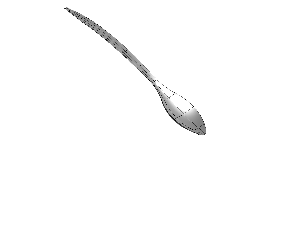
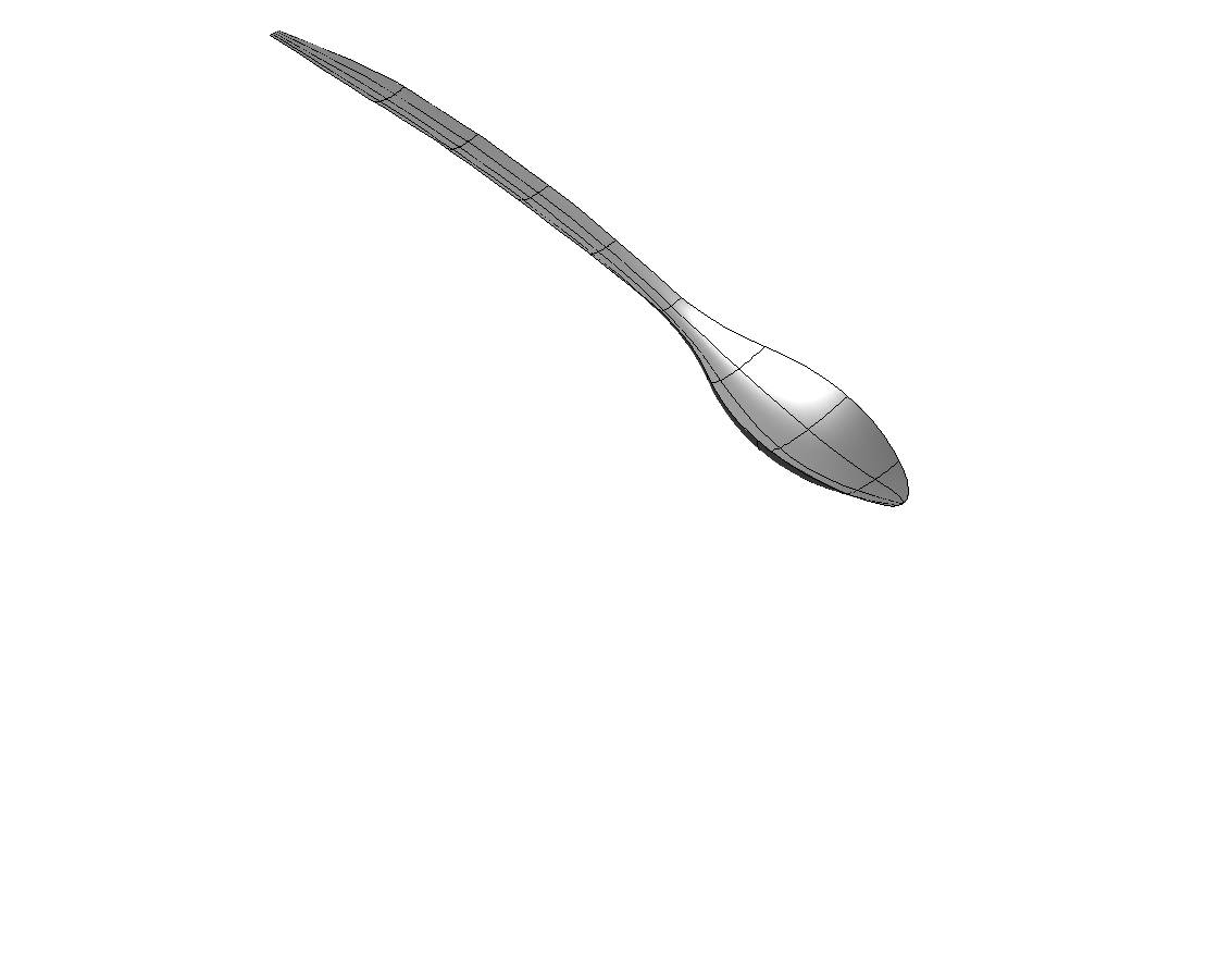
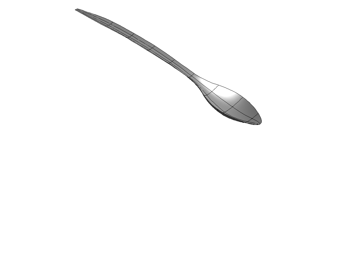
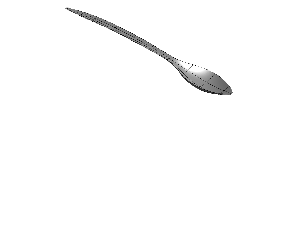
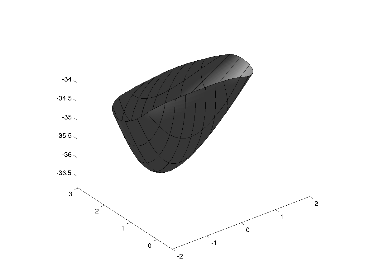
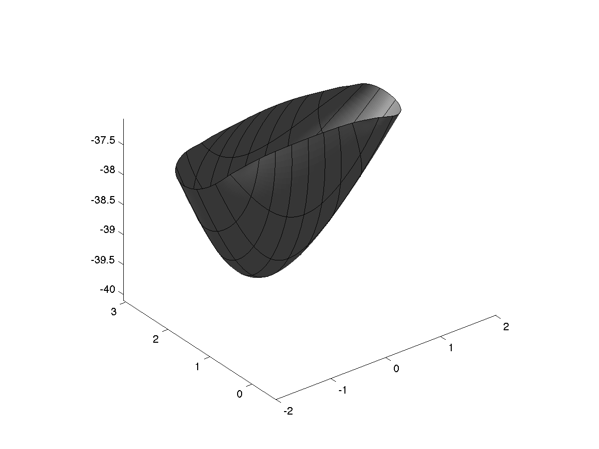
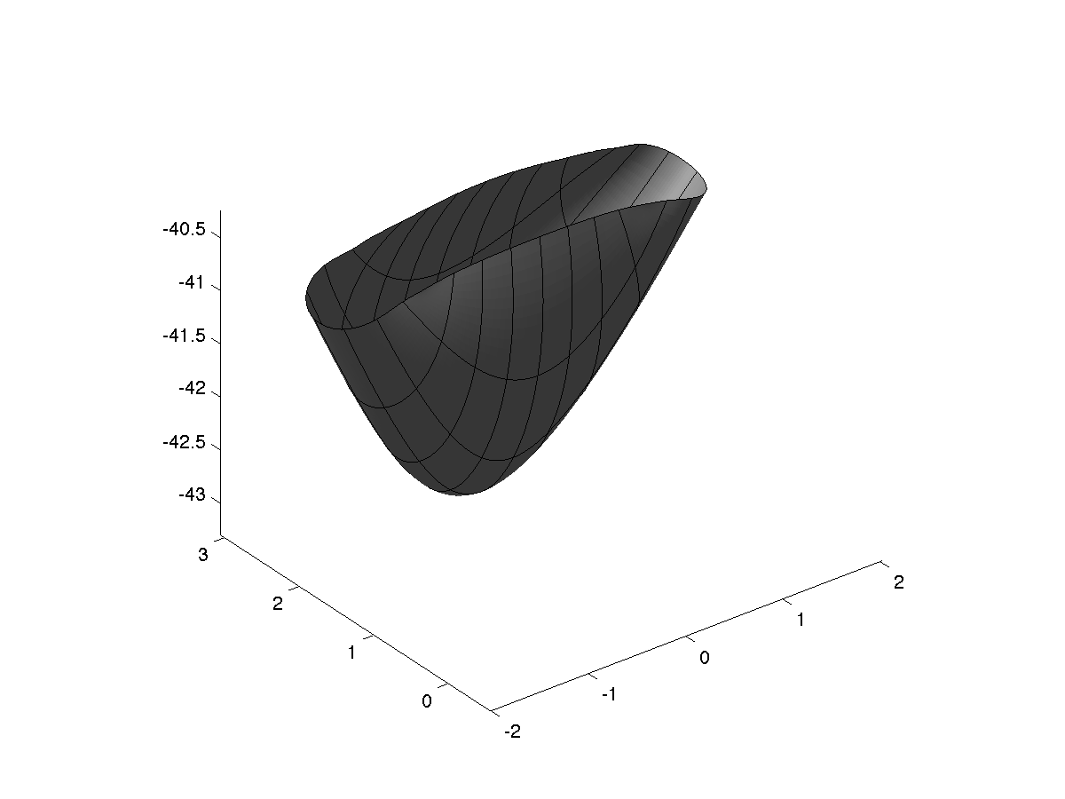
A natural framework for isogeometric fluid-structure interaction based on BEM-shell coupling

Luca Heltai\cofirst luca.heltai@sissa.it    Josef Kiendl\cofirst j.kiendl@tu-braunschweig.de    Antonio DeSimone antonio.desimone@sissa.it    Alessandro Reali alereali@unipv.it SISSA-International School for Advanced Studies
via Bonomea 265, 34136 Trieste - Italy
Institute for Applied Mechanics, Technische Universität Braunschweig
Bienroder Weg 87, 38106 Braunschweig Germany
Department of Civil Engineering and Architecture, University of Pavia
via Ferrata 3, 27100 Pavia - Italy
Institute for Advanced Study, Technische Universität München
Lichtenbergstraße 2a, 85748 Garching - Germany
Abstract

The interaction between thin structures and incompressible Newtonian fluids is ubiquitous both in nature and in industrial applications. In this paper we present an isogeometric formulation of such problems which exploits a boundary integral formulation of Stokes equations to model the surrounding flow, and a non linear Kirchhoff-Love shell theory to model the elastic behaviour of the structure. We propose three different coupling strategies: a monolithic, fully implicit coupling, a staggered, elasticity driven coupling, and a novel semi-implicit coupling, where the effect of the surrounding flow is incorporated in the non-linear terms of the solid solver through its damping characteristics. The novel semi-implicit approach is then used to demonstrate the power and robustness of our method, which fits ideally in the isogeometric paradigm, by exploiting only the boundary representation (B-Rep) of the thin structure middle surface.

keywords:
Isogeometric Analysis \sepBoundary Element Method \sepKirchhoff-Love theory \sepFluid-Structure Interaction \sepIncompressible Flows \sepShell-BEM coupling
journal: Computer Methods in Applied Mechanics and Engineering
\DeclareFixedFootnote\cofirst

Co-first authors. These authors contributed equally to the article.

\cortext

[cor]Corresponding author. Tel.: +49 0531 39194360

1 Introduction

One of the most attractive features of isogeometric analysis (IGA) HughesCottrellBazilevs-2005-a; CottrellHughesBazilevs-2009-a is the ability to bypass mesh generation and to perform direct design-to-analysis simulations, by employing the same class of functions used for geometry parameterization in CAGD packages during the analysis process.

Most modern CAD tools, however, are based on boundary representation (B-Rep) objects, making the use of volume-based finite element isogeometric analysis tools (FE-IGA) less attractive, since they require the extension of the computational domain inside (or outside) the enclosing (or enclosed) CAGD surface.

For thin structures, isogeometric shell models circumvent this issue since they only need a surface description of the structure. For fluid dynamics, isogeometric boundary element methods (IGA-BEM) also circumvent the issue mentioned above by reformulating the volumetric flow problem in boundary integral form. Such dimensionality reduction makes the coupling between boundary integral formulations and shell theory an ideal combination for a large class of fluid-structure interaction (FSI) problems, where thin structures interact with Newtonian incompressible flows, and it fits ideally in the IGA paradigm, by only requiring surface representations for both fluid and structural analyses.

FSI problems have been tackled with many different techniques, ranging from interface tracking, based on Arbitrary Lagrangian Eulerian (ALE) Bazilevs2008; Bazilevs201228; Dettmer20065754; DONEA1982689; Farhat199895; HUGHES1981329 or space–time methods Hansbo20044195; Hobner20042087; Takizawa2011; TEZDUYAR1992339; Tezduyar1992353; Tezduyar20062002, to interface capturing RotundoKimJiang-2015-a or immersed boundary (IBM) BoffiGastaldiHeltaiPeskin-2008-a; Heltai-2008-a; Heltai2012b; Hesch201251; Zhang20042051, or immersogeometric methods hsu_dynamic_2015; Kamensky2014. Most of the FSI applications in the isogeometric community rely on a FE-IGA approximation of the flow equations.

Some early attempts to model FSI problems using only B-Rep representations were common in biological applications AlougesDeSimoneHeltai-2011-a; ArroyoDeSimoneHeltai-2010-a; Arroyo30102012 and have been recently extended to a purely B-Rep isogeometric paradigm for the simulation of inflatable structures Opstal2012; VanOpstal2013; VanOpstal2015.

IGA-BEM and shell techniques have grown separately to mature and efficient simulation techniques. On the IGA-BEM side, a considerable effort has been put in the treatment of singular integration Heltai2014; Farutin2014, adaptivity Feischl2015; Feischl2015a, multipatch and trimmed surfaces Wang2015a; Wang2015b, efficient solvers TakahashiMatsumoto-2012-a; Marussig2015a, fracture simulations Peng; Peng2014, and acoustic wave problems Peake2015. Flow solvers using IGA-BEM proved to be very effective in the study of vesicles and membranes ArroyoDeSimoneHeltai-2010-a; Arroyo30102012; Joneidi2015, ship hydrodynamics KimLeeKerwin-2007-a; PolitisGinnisKaklis-2009-a; BelibassakisGerostathisKostas-2011-a; Belibassakis2013, and rigid wings and sails Manzoni2015, among many others.

For shell analysis, it can be said that IGA has initiated a renaissance in rotation-free thin shell models motivated by the high continuity of the NURBS discretization, which permits a direct implementation of such models. The first isogeometric formulation for geometrically nonlinear Kirchhoff–Love shells was introduced in kiendl_isogeometric_2009. A similar high continuity approach was presented in the pioneering works cirak_subdivision_2000; cirak_fully_2001. These formulations have then been employed for various applications such as wind turbine modeling BazHsu11a; BazHsu12b; HsuBaz12a; Korobenko:2013gw, cloth draping simulations lu_dynamic_2014, explicit finite strain analysis of membranes chen_explicit_2014, PHT-spline shell analysis nguyen-thanh_rotation_2011, and fracture modeling within an extended IGA approach nguyen_extended_2015. Recently, this formulation was extended to arbitrary hyperelastic materials in kiendl_isogeometric_2015. In the case of multipatch structures, the lack of rotational degrees of freedom requires additional treatment at patch connections in order to ensure the necessary C1superscript𝐶1C^{1}-continuity across patch interfaces. Different methods have been proposed, such as the bending strip method Kiendl_bending_2010, penalty formulations as in apostolatos_nitsche-type_2013; breitenberger_analysis_2015 or a Nitsche formulation as in guo_nitsche_2015. IGA has created a lot of interest and developments not only for thin shell models but also for Reissner-Mindlin shells benson_isogeometric_2010; dornisch_isogeometric_2013; dornisch_treatment_2014; uhm_tspline_2009. Morevoer, a hierarchic family of shells was presented in echter_hierarchic_2013 which includes Kirchhoff-Love, Reissner-Mindlin, and higher order shells. In benson_blended_2013, a blended shell formulation was presented, which is a combination of rotation-free shells benson_large_2011 in the patch interior and Reissner-Mindlin shells benson_isogeometric_2010 at the boundary. Furthermore, many developments have been done as well on isogeometric solid shells bouclier_efficient_2013; caseiro_on_2014; caseiro_assumed_2015; hosseini_isogeometric_2013; hosseini_isogeometric_2014. Thin shell models, as those presented in kiendl_isogeometric_2009; kiendl_isogeometric_2015, are purely surface-based, in a sense that the shell is completely defined by its middle surface and the shell kinematics are completely described by the middle surface metric and curvature properties. This allows for a direct integration of IGA into CAD systems breitenberger_analysis_2015; schmidt_realization_2010, it facilitates the coupling of shell structures and fluids in fluid-structure interaction (FSI) applications due to the lack of rotational degrees of freedom bazilevs_3d_2011; BazHsu12b; HsuBaz12a, and it is perfectly suited for the coupling with an IGA-BEM fluid solver as we propose in this paper.

The rest of this paper is organized as follows. In section 2 we present a brief overview of isogeometric NURBS spaces. The continuous FSI problem we want to tackle is introduced in section 3, and an analysis of the coupling strategies is presented in section 4. Sections 5 and 6 present respectively the numerical treatment of the BEM and Shell parts, while in sections 7 and 8 we present some numerical examples and draw some conclusions.

2 Overview of isogeometric NURBS spaces

Given a nondecreasing knot vector Θ={k0,k1,,kn+p}Θsubscript𝑘0subscript𝑘0subscript𝑘0\Theta=\{k_{0},k_{1},...,k_{n+p}\}, the n𝑛n B-splines of degree p𝑝p are defined by the recurrence relation

B(i,0)(s)={1, if kis<ki+10, otherwise,superscript𝐵𝑖0𝑠cases1 if subscript𝑘𝑖𝑠subscript𝑘𝑖10 otherwiseB^{(i,0)}(s)=\begin{cases}1,&\mbox{ if }k_{i}\leq s<k_{i+1}\\ 0,&\mbox{ otherwise},\end{cases} (1)

for p=0𝑝0p=0, while for p>0𝑝0p>0 we have

B(i,p)(s)=τ(i,p)(s)B(i,p1)(s)τ(i+1,p)(s)B(i+1,p1)(s),superscript𝐵𝑖𝑝𝑠superscript𝜏𝑖𝑝𝑠superscript𝐵𝑖𝑝1𝑠superscript𝜏𝑖1𝑝𝑠superscript𝐵𝑖1𝑖1𝑠B^{(i,p)}(s)=\tau^{(i,p)}(s)B^{(i,p-1)}(s)-\tau^{(i+1,p)}(s)B^{(i+1,p-1)}(s), (2)

for i=0,,n1𝑖0𝑛1i=0,...,n-1, where

τ(i,p)(s):={skiki+pki if ki+pki0, otherwise.assignsuperscript𝜏𝑖𝑝𝑠cases𝑠superscript𝑘𝑖superscript𝑘𝑖𝑝superscript𝑘𝑖 if superscript𝑘𝑖𝑝superscript𝑘𝑖0 otherwise\tau^{(i,p)}(s):=\begin{cases}\displaystyle\frac{s-k^{i}}{k^{i+p}-k^{i}}&\mbox{ if }k^{i+p}\neq k^{i}\\ 0,&\mbox{ otherwise}.\end{cases} (3)

The above recurrence relation can be evaluated in a numerically stable way by the de Boor algorithm (see, for example, PieglTiller-1997-a). Between two distinct knots, a B-spline is of continuity class 𝒞superscript𝒞\mathcal{C}^{\infty}, at a single knot it is 𝒞p1superscript𝒞𝑝1\mathcal{C}^{p-1}, and, if a knot is repeated q𝑞q times, the continuity is reduced to 𝒞pqsuperscript𝒞𝑝𝑞\mathcal{C}^{p-q}. A knot can be repeated at most q=p+1𝑞𝑝1q=p+1 times resulting in a discontinuity (𝒞1superscript𝒞1\mathcal{C}^{-1}) at that location.

NURBS basis functions are readily obtained from B-Splines by assigning a positive weight wisubscript𝑤𝑖w_{i} to each basis spline function and defining the corresponding NURBS basis function as

Ni(s):=wiB(i,p)(s)j=0n1wjB(j,p)(s).assignsuperscript𝑁𝑖𝑠superscript𝑤𝑖superscript𝐵𝑖𝑝𝑠superscriptsubscript𝑗0𝑛1superscript𝑤𝑗superscript𝐵𝑗𝑝𝑠N^{i}(s):=\frac{w^{i}B^{(i,p)}(s)}{\sum_{j=0}^{n-1}w^{j}B^{(j,p)}(s)}. (4)

Notice that also the NURBS basis have the partition of unity property, and B-Splines can be considered a special case of NURBS by taking all weights to be identical. Taking two knot vectors ΘisubscriptΘ𝑖\Theta_{i}, with i=0,1𝑖01i=0,1, one can construct the NURBS basis functions for two-dimensional surfaces embedded in three dimensional space by tensor products. Indicating with 𝒔:=[s0,s1]assign𝒔subscript𝑠0subscript𝑠0\boldsymbol{s}:=[s_{0},s_{1}] a point in 2superscript2\Re^{2} and 𝒊:=(i0,i1)assign𝒊subscript𝑖0subscript𝑖0\boldsymbol{i}:=(i_{0},i_{1}) a two dimensional multi-index belonging to the set

𝒥:={𝒋=(j0,j1),0jk<nk,k=0,1},\mathcal{J}:=\{\boldsymbol{j}=(j_{0},j_{1}),\quad 0\leq j_{k}<n_{k},\quad k=0,1\}, (5)

the bi-variate B-Splines and NURBS basis functions are given by

B𝒊,𝒑(𝒔):=B(i0,p0)(s0)B(i1,p1)(s1),N𝒊(𝒔):=w𝒊B(𝒊,𝒑)(𝒔)𝒋𝒥w𝒋B(𝒋,𝒑)(𝒔),formulae-sequenceassignsuperscript𝐵𝒊𝒑𝒔superscript𝐵subscript𝑖0subscript𝑖0subscript𝑠0superscript𝐵subscript𝑖1subscript𝑖1subscript𝑠1assignsuperscript𝐵𝒊𝒑𝒔superscript𝐵subscript𝑖0subscript𝑖0subscript𝑠0superscript𝐵subscript𝑖1subscript𝑖1subscript𝑠1B^{\boldsymbol{i},\boldsymbol{p}}(\boldsymbol{s}):=B^{(i_{0},p_{0})}(s_{0})B^{(i_{1},p_{1})}(s_{1}),\qquad N^{\boldsymbol{i}}(\boldsymbol{s}):=\frac{w{\boldsymbol{i}}B^{(\boldsymbol{i},\boldsymbol{p})}(\boldsymbol{s})}{\sum_{\boldsymbol{j}\in\mathcal{J}}w^{\boldsymbol{j}}B^{(\boldsymbol{j},\boldsymbol{p})}(\boldsymbol{s})}, (6)

where 𝒊𝒊\boldsymbol{i}, 𝒑𝒑\boldsymbol{p} and 𝒋𝒋\boldsymbol{j} are all multi-indices. The multi-index 𝒑=(p0,p1)𝒑subscript𝑝0subscript𝑝0\boldsymbol{p}=(p_{0},p_{1}) is used to keep track of the degrees of the B-Splines in each direction, while 𝒏=(n0,n1)𝒏subscript𝑛0subscript𝑛0\boldsymbol{n}=(n_{0},n_{1}) is used to keep track of the number of basis functions in each direction. Notice that in Equations (4) and (6) we dropped the superscripts p𝑝p and 𝒑𝒑\boldsymbol{p} from the definition of the NURBS basis functions N𝒊superscript𝑁𝒊N^{\boldsymbol{i}}, to ease the notation in the rest of the paper.

As a generalization of the one dimensional case, if we take a collection of n:=n0n1assign𝑛subscript𝑛0subscript𝑛1n:=n_{0}n_{1} control points in 3superscript3\Re^{3}, we can represent a two dimensional manifold in a three dimensional space as the image of the map

3𝒙(𝒔):=𝒊𝒥𝑷𝒊N𝒊(𝒔)𝒔2.formulae-sequencesuperset-ofsuperscript3𝒙𝒔assignsubscript𝒊𝒥superscript𝑷𝒊superscript𝑁𝒊𝒔superset-ofsuperscript3𝒙𝒔assignsubscript𝒊𝒥superscript𝑷𝒊superscript𝑁𝒊𝒔\Re^{3}\supset{\boldsymbol{x}}(\boldsymbol{s}):=\sum_{\boldsymbol{i}\in\mathcal{J}}\boldsymbol{P}^{\boldsymbol{i}}N^{\boldsymbol{i}}(\boldsymbol{s})\qquad\boldsymbol{s}\in\Re^{2}. (7)

The set of control points 𝑷𝒊superscript𝑷𝒊\boldsymbol{P}^{\boldsymbol{i}} with 𝒊𝒥𝒊𝒥\boldsymbol{i}\in\mathcal{J} is usually referred to as control net. The domain of the map 𝒙(𝒔)𝒙𝒔{\boldsymbol{x}}(\boldsymbol{s}) is the set

B2:=[k00,kn0+p00]×[k01,kn1+p11]2,assignsuperscript𝐵2subscriptsuperscript𝑘00subscriptsuperscript𝑘00subscriptsuperscript𝑘10subscriptsuperscript𝑘10superscript2B^{2}:=[k^{0}_{0},k^{0}_{n_{0}+p_{0}}]\times[k^{1}_{0},k^{1}_{n_{1}+p_{1}}]\subset\Re^{2}, (8)

where kjisubscriptsuperscript𝑘𝑖𝑗k^{i}_{j} is the j𝑗j-th knot in the i𝑖i-th knot vector ΘisubscriptΘ𝑖\Theta_{i}.

In what follows, we will use greek indices α,β𝛼𝛽\alpha,\beta to indicate components in the two dimensional manifold (i.e., from zero to one) and latin indices to indicate components in the three dimensional embedding manifold.

The tangential vectors on a point on the surface are given by the covariant base vectors 𝒈αsubscript𝒈𝛼\boldsymbol{g}_{\alpha}:

𝒈α(𝒔)=𝒙(𝒔)sα=𝒙,α(𝒔)\displaystyle\boldsymbol{g}_{\alpha}(\boldsymbol{s})=\frac{\partial\boldsymbol{x}(\boldsymbol{s})}{\partial s^{\alpha}}=\boldsymbol{x}_{,\alpha}(\boldsymbol{s}) (9)

Contravariant base vectors 𝒈α(𝒔)superscript𝒈𝛼𝒔\boldsymbol{g}^{\alpha}(\boldsymbol{s}) are obtained through the relation 𝒈α𝒈β=δβαsuperscript𝒈𝛼subscript𝒈𝛽subscriptsuperscript𝛿𝛼𝛽\boldsymbol{g}^{\alpha}\cdot\boldsymbol{g}_{\beta}=\delta^{\alpha}_{\beta}, where δβαsubscriptsuperscript𝛿𝛼𝛽\delta^{\alpha}_{\beta} is the Kronecker delta. Furthermore, we introduce the unit normal vector 𝒈3subscript𝒈3\boldsymbol{g}_{3}:

𝒈3(𝒔)subscript𝒈3𝒔\displaystyle\boldsymbol{g}_{3}(\boldsymbol{s}) =𝒈α(𝒔)×𝒈β(𝒔)|𝒈α(𝒔)×𝒈β(𝒔)|.absentsubscript𝒈𝛼𝒔subscript𝒈𝛽𝒔subscript𝒈𝛼𝒔subscript𝒈𝛽𝒔\displaystyle=\frac{\boldsymbol{g}_{\alpha}(\boldsymbol{s})\times\boldsymbol{g}_{\beta}(\boldsymbol{s})}{|\boldsymbol{g}_{\alpha}(\boldsymbol{s})\times\boldsymbol{g}_{\beta}(\boldsymbol{s})|}. (10)

With the tangential and normal vectors, we can write the first and second fundamental forms of the surface, respectively:

gαβ(𝒔)subscript𝑔𝛼𝛽𝒔\displaystyle g_{\alpha\beta}(\boldsymbol{s}) =𝒈α(𝒔)𝒈β(𝒔)absentsubscript𝒈𝛼𝒔subscript𝒈𝛽𝒔\displaystyle=\boldsymbol{g}_{\alpha}(\boldsymbol{s})\cdot\boldsymbol{g}_{\beta}(\boldsymbol{s}) (11)
bαβ(𝒔)subscript𝑏𝛼𝛽𝒔\displaystyle b_{\alpha\beta}(\boldsymbol{s}) =𝒈α,β(𝒔)𝒈3(𝒔)absentsubscript𝒈𝛼𝛽𝒔subscript𝒈3𝒔\displaystyle=\boldsymbol{g}_{\alpha,\beta}(\boldsymbol{s})\cdot\boldsymbol{g}_{3}(\boldsymbol{s}) (12)

where gαβsubscript𝑔𝛼𝛽g_{\alpha\beta} and bαβsubscript𝑏𝛼𝛽b_{\alpha\beta} represent the metric and curvature coefficients of the surface.

Integrals on the two-dimensional manifold 𝒙(B2)𝒙superscript𝐵2\boldsymbol{x}(B^{2}) can be pulled back to the domain B2superscript𝐵2B^{2} using the standard transformation rule

𝒙(B2)f(𝒙)dA=B2f(𝒙(𝒔))J(𝒔)d𝒔,subscript𝒙superscript𝐵2𝑓𝒙d𝐴subscriptsuperscript𝐵2𝑓𝒙𝒔𝐽𝒔d𝒔\int_{\boldsymbol{x}(B^{2})}f(\boldsymbol{x})\,\textrm{d}A=\int_{B^{2}}f(\boldsymbol{x}(\boldsymbol{s}))J(\boldsymbol{s})\,\textrm{d}\boldsymbol{s}, (13)

where we indicated with J(𝒔)𝐽𝒔J(\boldsymbol{s}) the square root of the determinant of the first fundamental form:

J(𝒔):=det(gαβ(𝒔)).assign𝐽𝒔subscript𝑔𝛼𝛽𝒔J(\boldsymbol{s}):=\sqrt{\det(g_{\alpha\beta}(\boldsymbol{s}))}. (14)

A standard (scalar) isogeometric finite dimensional space on a two-dimensional manifold is readily obtained by considering the span of the functions ϕ𝒊:=N𝒊𝒙1assignsuperscriptitalic-ϕ𝒊superscript𝑁𝒊superscript𝒙1\phi^{\boldsymbol{i}}:=N^{\boldsymbol{i}}\circ\boldsymbol{x}^{-1}:

Vh:=span{ϕ𝒊(𝒚)}𝒊𝒥,𝒚𝒙(B2)3,formulae-sequenceassignsubscript𝑉spansubscriptsuperscriptitalic-ϕ𝒊𝒚𝒊𝒥assignsubscript𝑉spansubscriptsuperscriptitalic-ϕ𝒊𝒚𝒊𝒥V_{h}:=\text{span}\{\phi^{\boldsymbol{i}}(\boldsymbol{y})\}_{\boldsymbol{i}\in\mathcal{J}},\qquad\boldsymbol{y}\in\boldsymbol{x}(B^{2})\subset\Re^{3}, (15)

where ϕ𝒊superscriptitalic-ϕ𝒊\phi^{\boldsymbol{i}} are such that

ϕ𝒊(𝒙(𝒔))=N𝒊(𝒔),𝒔B2.formulae-sequencesuperscriptitalic-ϕ𝒊𝒙𝒔superscript𝑁𝒊𝒔superscriptitalic-ϕ𝒊𝒙𝒔superscript𝑁𝒊𝒔\phi^{\boldsymbol{i}}(\boldsymbol{x}(\boldsymbol{s}))=N^{\boldsymbol{i}}(\boldsymbol{s}),\qquad\forall\boldsymbol{s}\in B^{2}. (16)

The dimension of the space Vhsubscript𝑉V_{h} is n=n0n1𝑛subscript𝑛0subscript𝑛1n=n_{0}n_{1} and it is equal to the number of control points that define the geometry of the problem. If we introduce the multi-index set 𝒥3superscript𝒥3\mathcal{J}^{3}, as done for scalar functions in equation (5),

𝒥3:={𝒋=(j0,j1,j2),0jk<3×nk,k=0,1,2},\mathcal{J}^{3}:=\{\boldsymbol{j}=(j_{0},j_{1},j_{2}),\quad 0\leq j_{k}<3\times n_{k},\quad k=0,1,2\}, (17)

then a finite dimensional space for vector fields of three components is obtained by considering

Vh3:=span{𝚽𝑰(𝒚)}𝑰𝒥3𝒚𝒙(B2)3,formulae-sequenceassignsubscriptsuperscript𝑉3spansubscriptsuperscript𝚽𝑰𝒚𝑰superscript𝒥3assignsubscriptsuperscript𝑉3spansubscriptsuperscript𝚽𝑰𝒚𝑰superscript𝒥3V^{3}_{h}:=\text{span}\{\boldsymbol{\Phi}^{\boldsymbol{I}}(\boldsymbol{y})\}_{\boldsymbol{I}\in\mathcal{J}^{3}}\qquad\boldsymbol{y}\in\boldsymbol{x}(B^{2})\subset\Re^{3}, (18)

where the basis functions 𝚽𝑰superscript𝚽𝑰\boldsymbol{\Phi}^{\boldsymbol{I}} are such that

𝚽𝑰(𝒚):=𝒆aϕ𝒋(𝒚),𝑰=(3j0+a,3j1+a)=3𝒋+a.formulae-sequenceassignsuperscript𝚽𝑰𝒚subscript𝒆𝑎superscriptitalic-ϕ𝒋𝒚assignsuperscript𝚽𝑰𝒚subscript𝒆𝑎superscriptitalic-ϕ𝒋𝒚\boldsymbol{\Phi}^{\boldsymbol{I}}(\boldsymbol{y}):=\boldsymbol{e}_{a}\phi^{\boldsymbol{j}}(\boldsymbol{y}),\qquad\boldsymbol{I}=(3j_{0}+a,3j_{1}+a)=3\boldsymbol{j}+a. (19)

The multi index 𝑰𝑰\boldsymbol{I} is meant to transform the multi-index 𝒋𝒥𝒋𝒥\boldsymbol{j}\in\mathcal{J} plus the component index a𝑎a into a unique global identifier for the 𝑰𝑰\boldsymbol{I}-th basis function. In what follows, we use upper case bold latin indices 𝑰,𝑱𝑰𝑱\boldsymbol{I},\boldsymbol{J} to indicate the global numbering of the basis functions defining the space Vh3subscriptsuperscript𝑉3V^{3}_{h}, lower case latin indices i,j,k𝑖𝑗𝑘i,j,k to label spacial coordinates in [0,d)0𝑑[0,d) and greek indices α,β𝛼𝛽\alpha,\beta to label parameter coordinates in [0,1]01[0,1]. Unless otherwise stated, we use Einstein summation convention. A vector function of three components 𝒇(𝒙)𝒇𝒙\boldsymbol{f}(\boldsymbol{x}) in the space Vh3superscriptsubscript𝑉3V_{h}^{3} is identified by its coefficient vector 𝒇𝒇\boldsymbol{f} such that

Vh3𝒇(𝒙):=𝒇𝑰𝚽𝑰(𝒙),containssubscriptsuperscript𝑉3𝒇𝒙assignsuperscript𝒇𝑰superscript𝚽𝑰𝒙V^{3}_{h}\ni\boldsymbol{f}(\boldsymbol{x}):=\boldsymbol{f}^{\boldsymbol{I}}\boldsymbol{\Phi}^{\boldsymbol{I}}(\boldsymbol{x}), (20)

where, with a slight abuse of notation, we denote the vector of coefficients 𝒇𝒇\boldsymbol{f} with the same symbol as the function 𝒇(𝒙)𝒇𝒙\boldsymbol{f}(\boldsymbol{x}) but without the argument “(𝒙)𝒙(\boldsymbol{x})”.

3 Fluid-Structure Interaction

We are interested in studying the interaction between a thin deformable elastic body and an incompressible fluid. We consider a model problem where the inertial terms of the fluid are negligible when compared with both the fluid viscosity and the inertial terms of the solid. We assume that the deformable body occupies at time t𝑡t the region Ωs(t)=𝒙(Ω0s)3superscriptΩs𝑡𝒙subscriptsuperscriptΩs0superscript3\Omega^{\text{s}}(t)=\boldsymbol{x}(\Omega^{\text{s}}_{0})\subset\Re^{3} and that the rest of the space is entirely occupied by an incompressible fluid whose time dependent domain is Ωf(t)=3Ωs(t)superscriptΩf𝑡superscript3superscriptΩs𝑡\Omega^{\text{f}}(t)=\Re^{3}\setminus\Omega^{\text{s}}(t).

The fluid and solid domains are coupled through non-slip conditions and through balance equations across the boundary of the solid domain Γfsi(t):=Ωs(t)assignsuperscriptΓfsi𝑡superscriptΩs𝑡\Gamma^{\text{fsi}}(t):=\partial\Omega^{\text{s}}(t). We will describe the fluid equations in Eulerian form, where the primal variables are the velocity field of the fluid 𝒗𝒗{\boldsymbol{v}} and its pressure p𝑝p at fixed points in space, while we use a Lagrangian description for the the solid, where each point 𝑿𝑿\boldsymbol{X} represents a fixed material point in Ω0ssubscriptsuperscriptΩs0\Omega^{\text{s}}_{0} mapped by the transformation 𝒙:Ω0×[0,T]d:𝒙maps-tosubscriptΩ00𝑇superscript𝑑\boldsymbol{x}:\Omega_{0}\times[0,T]\mapsto\Re^{d} to its current location 𝒙(𝑿,t)𝒙𝑿𝑡\boldsymbol{x}(\boldsymbol{X},t) at time t𝑡t.

For convenience, we introduce the deformation field 𝒖(𝑿,t)𝒖𝑿𝑡\boldsymbol{u}(\boldsymbol{X},t), such that 𝒖(𝑿,t)=𝒙(𝑿,t)𝑿𝒖𝑿𝑡𝒙𝑿𝑡𝑿\boldsymbol{u}(\boldsymbol{X},t)=\boldsymbol{x}(\boldsymbol{X},t)-\boldsymbol{X}. The transformation map 𝒙(,t):Ω0sΩs(t):𝒙𝑡maps-tosubscriptsuperscriptΩs0superscriptΩs𝑡\boldsymbol{x}(\cdot,t):\Omega^{\text{s}}_{0}\mapsto\Omega^{\text{s}}(t) is assumed to be invertible and bi-lipschitz for each time t𝑡t in the interval [0,T]0𝑇[0,T], i.e., the determinant J𝐽J of the deformation gradient 𝑭:=Grad𝒙(𝑿,t):=𝑿𝒙(𝑿,t)=𝑿𝒖+𝑰assign𝑭Grad𝒙𝑿𝑡assignsubscript𝑿𝒙𝑿𝑡subscript𝑿𝒖𝑰\boldsymbol{F}:=\text{Grad}~{}\boldsymbol{x}(\boldsymbol{X},t):=\nabla_{\boldsymbol{X}}\boldsymbol{x}(\boldsymbol{X},t)=\nabla_{\boldsymbol{X}}\boldsymbol{u}+\boldsymbol{I} is strictly positive and 𝑭𝑭\boldsymbol{F} is bounded. We denote the gradient and the divergence with respect to the 𝑿𝑿\boldsymbol{X} variable with Grad and Div.

The equations of motion of the system can be written as:

𝝈:=ηΔ𝒗+p=0assign𝝈𝜂Δ𝒗𝑝0\displaystyle-\nabla\cdot\boldsymbol{\sigma}:=-\eta\Delta{\boldsymbol{v}}+\nabla p=0\qquad in Ωf(t)in superscriptΩf𝑡\displaystyle\text{ in }\Omega^{\text{f}}(t) (21a)
𝒗=0𝒗0\displaystyle\nabla\cdot{\boldsymbol{v}}=0 in Ωf(t)in superscriptΩf𝑡\displaystyle\text{ in }\Omega^{\text{f}}(t) (21b)
ρ2𝒖t2Div(𝑭𝑺)𝒃=0𝜌superscript2𝒖superscript𝑡2Div𝑭𝑺𝒃0\displaystyle\rho\frac{\partial^{2}\boldsymbol{u}}{\partial t^{2}}-\text{Div}\big{(}\boldsymbol{F}\cdot\boldsymbol{S}\big{)}-\boldsymbol{b}=0\qquad in Ω0sin subscriptsuperscriptΩs0\displaystyle\text{ in }\Omega^{\text{s}}_{0} (21c)
J𝝈𝑭T𝝂0=𝑭𝑺𝝂0𝐽𝝈superscript𝑭𝑇subscript𝝂0𝑭𝑺subscript𝝂0\displaystyle J\boldsymbol{\sigma}\cdot\boldsymbol{F}^{-T}\cdot\boldsymbol{\nu}_{0}=\boldsymbol{F}\cdot\boldsymbol{S}\cdot\boldsymbol{\nu}_{0} on Γ0fsion subscriptsuperscriptΓfsi0\displaystyle\text{ on }\Gamma^{\text{fsi}}_{0} (21d)
𝒗(𝒙(𝑿,t),t)=𝒖(𝑿,t)t=:𝒖˙(𝑿,t)\displaystyle{\boldsymbol{v}}(\boldsymbol{x}(\boldsymbol{X},t),t)=\frac{\partial\boldsymbol{u}(\boldsymbol{X},t)}{\partial t}=:\dot{\boldsymbol{u}}(\boldsymbol{X},t)\qquad on Γ0fsion subscriptsuperscriptΓfsi0\displaystyle\text{ on }\Gamma^{\text{fsi}}_{0} (21e)
𝒖|t=0=𝒖0evaluated-at𝒖𝑡0subscript𝒖0\displaystyle\boldsymbol{u}|_{t=0}=\boldsymbol{u}_{0} in Ω0sin subscriptsuperscriptΩs0\displaystyle\text{ in }\Omega^{\text{s}}_{0} (21f)
𝒖˙|t=0=𝒗0evaluated-at˙𝒖𝑡0subscript𝒗0\displaystyle\dot{\boldsymbol{u}}|_{t=0}={\boldsymbol{v}}_{0} in Ω0s.in subscriptsuperscriptΩs0\displaystyle\text{ in }\Omega^{\text{s}}_{0}. (21g)

Where η,𝝈𝜂𝝈\eta,\boldsymbol{\sigma} are the fluid viscosity and Cauchy stress tensor respectively, while ρ,𝑺𝜌𝑺\rho,\boldsymbol{S} are the solid density and second Piola-Kirchhoff stress tensor, respectively, and 𝒃𝒃\boldsymbol{b} is a body load acting on the solid, i.e., gravity. The quantities 𝒗0,𝒖0,𝝂0subscript𝒗0subscript𝒗0subscript𝒗0{\boldsymbol{v}}_{0},\boldsymbol{u}_{0},\boldsymbol{\nu}_{0} are the initial solid velocity, initial solid displacement, and outer normal to the reference configuration.

We remark here that at low Reynolds numbers time dependency in the equations of motion of the fluid can only occur due to boundary conditions and through the time dependent changes in the shape of the domain (i.e., Ωf(t)superscriptΩf𝑡\Omega^{\text{f}}(t)). For this reason, in equation (21) there are no initial conditions for the fluid velocity, which is assumed to adjust instantaneously to changes in boundary conditions and in domain shape.

Equations (21a) and (21b) represent the conservation of momentum and mass in Eulerian form for a low Reynolds number flow, while equation (21c) is the conservation of momentum for a solid body, written in Lagrangian form.

We will restrict our attention to problems for which Ωs(t)superscriptΩs𝑡\Omega^{\text{s}}(t) is a thin shell and we will consider the Kirchhoff-Love shell theory, where the director, i.e., a vector normal to the middle surface, is assumed to remain normal to the middle surface in the deformed configuration (i.e., parallel to 𝒈3subscript𝒈3\boldsymbol{g}_{3}). With this assumption, the configuration of the shell is uniquely determined once we know the configuration of its middle surface Γ(t)Γ𝑡\Gamma(t), making this an ideal candidate for a coupled FSI problem which requires only a surface description.

To summarise, here are the list of all assumptions we make in our model:

  • the inertial terms of the fluid are negligible when compared with both the fluid viscosity and the inertial terms of the solid;

  • the transversal dimension hh of the solid is much smaller than all other directions, and can be neglected when considering the geometry of the problem;

  • the coupling conditions between the solid and the fluid are applied at the middle surface Γ(t)Γ𝑡\Gamma(t) of the solid.

With these assumptions, the fluid equations reduce to Stokes equations on the domain 3Γ(t)superscript3Γ𝑡\Re^{3}\setminus\Gamma(t). For a given prescribed velocity on Γ(t)Γ𝑡\Gamma(t), we can compute the force per unit area that the fluid exerts on the middle surface of the solid, by pulling the jump of the fluid normal stress on Γ(t)Γ𝑡\Gamma(t) back to the solid reference configuration.

We define the operator that performs this pull back DN𝒖𝐷subscript𝑁𝒖D\!\!N_{\!\boldsymbol{u}}, i.e., a Dirichlet to Neumann map such that:

𝒇fsi=JDN𝒖𝒗g.superscript𝒇fsi𝐽𝐷subscript𝑁𝒖subscript𝒗𝑔\boldsymbol{f}^{\text{fsi}}=JD\!\!N_{\!\boldsymbol{u}}{\boldsymbol{v}}_{g}. (22)

Given a Dirichlet datum 𝒗gsubscript𝒗𝑔{\boldsymbol{v}}_{g} on the middle surface Γ(t)Γ𝑡\Gamma(t), this returns the pull back of the jump of the normal stress associated with the solution of the fluid problem, i.e.,

𝝈:=assign𝝈absent\displaystyle-\nabla\cdot\boldsymbol{\sigma}:= ηΔ𝒗+p=0𝜂Δ𝒗𝑝0\displaystyle-\eta\Delta{\boldsymbol{v}}+\nabla p=0\qquad in 3Γ(t)in superscript3Γ𝑡\displaystyle\text{ in }\Re^{3}\setminus\Gamma(t) (23a)
𝒗=0𝒗0\displaystyle\nabla\cdot{\boldsymbol{v}}=0 in 3Γ(t)in superscript3Γ𝑡\displaystyle\text{ in }\Re^{3}\setminus\Gamma(t) (23b)
𝒗=𝒗g𝒗subscript𝒗𝑔\displaystyle{\boldsymbol{v}}={\boldsymbol{v}}_{g} on Γ(t)on Γ𝑡\displaystyle\text{ on }\Gamma(t) (23c)
J1𝒇fsi=[[𝝈]]𝒈3superscript𝐽1superscript𝒇fsidelimited-[]delimited-[]𝝈subscript𝒈3\displaystyle J^{-1}\boldsymbol{f}^{\text{fsi}}=\left[\!\left[\boldsymbol{\sigma}\right]\!\right]\cdot\boldsymbol{g}_{3} on Γ(t),on Γ𝑡\displaystyle\text{ on }\Gamma(t), (23d)

where the symbol [[𝝈]]delimited-[]delimited-[]𝝈\left[\!\left[\boldsymbol{\sigma}\right]\!\right] represents the difference between 𝝈𝝈\boldsymbol{\sigma} across the middle surface Γ(t)Γ𝑡\Gamma(t).

For the structural analysis, we consider a Kirchhoff-Love shell in large deformations and small strains, i.e., a St.-Venant-Kirchhoff material model is applied. In the following, we present the weak form of the problem, based on the principal of virtual work.

We will indicate with 𝒙(𝒔,t)𝒙𝒔𝑡\boldsymbol{x}(\boldsymbol{s},t) the current configuration of the middle surface with respect to the curvilinear coordinates 𝒔𝒔\boldsymbol{s}, and with 𝑿(𝒔)𝑿𝒔\boldsymbol{X}(\boldsymbol{s}) the middle surface in the undeformed configuration. Analogously to equations (9)-(12), we define the tangent vectors 𝑮αsubscript𝑮𝛼\boldsymbol{G}_{\alpha}, the unit normal vector 𝑮3subscript𝑮3\boldsymbol{G}_{3}, the metric coefficients Gαβsubscript𝐺𝛼𝛽G_{\alpha\beta} and the curvature coefficients Bαβsubscript𝐵𝛼𝛽B_{\alpha\beta} for the undeformed configuration 𝑿(𝒔)𝑿𝒔\boldsymbol{X}(\boldsymbol{s}).

As strain measure we use the the Green-Lagrange strain tensor, where only in-plane strains are considered, 𝑬=Eαβ𝑮α𝑮β𝑬tensor-productsubscript𝐸𝛼𝛽superscript𝑮𝛼superscript𝑮𝛽\boldsymbol{E}=E_{\alpha\beta}\,\boldsymbol{G}^{\alpha}\otimes\boldsymbol{G}^{\beta}, with:

Eαβsubscript𝐸𝛼𝛽\displaystyle E_{\alpha\beta} =εαβ+θ3καβabsentsubscript𝜀𝛼𝛽superscript𝜃3subscript𝜅𝛼𝛽\displaystyle=\varepsilon_{\alpha\beta}+\theta^{3}\kappa_{\alpha\beta} (24)
εαβsubscript𝜀𝛼𝛽\displaystyle\varepsilon_{\alpha\beta} =12(gαβGαβ)absent12subscript𝑔𝛼𝛽subscript𝐺𝛼𝛽\displaystyle=\frac{1}{2}(g_{\alpha\beta}-G_{\alpha\beta}) (25)
καβsubscript𝜅𝛼𝛽\displaystyle\kappa_{\alpha\beta} =Bαβbαβabsentsubscript𝐵𝛼𝛽subscript𝑏𝛼𝛽\displaystyle=B_{\alpha\beta}-b_{\alpha\beta} (26)

where εαβsubscript𝜀𝛼𝛽\varepsilon_{\alpha\beta} represents the membrane strain while καβsubscript𝜅𝛼𝛽\kappa_{\alpha\beta} describes the change in curvature or bending (pseudo-)strain. As stress measure, we use the energetically conjugate second Piola-Kirchhoff stress tensor 𝑺𝑺\boldsymbol{S}:

𝑺𝑺\displaystyle\boldsymbol{S} =:𝑬:absent𝑬\displaystyle=\mathbb{C}:\boldsymbol{E} (27)

where \mathbb{C} is the fourth-order material tensor. Stresses are represented by the stress resultants 𝒏𝒏\boldsymbol{n} and 𝒎𝒎\boldsymbol{m}, which are the normal forces and bending moments, respectively. They are obtained by integrating the constant and the linear parts separately through the shell thickness hh as follows:

𝒏𝒏\displaystyle\boldsymbol{n} =h/2h/2𝑺(s3=0)ds3=h^:𝜺:absentsuperscriptsubscript22𝑺superscript𝑠30differential-dsuperscript𝑠3^𝜺\displaystyle=\int_{-h/2}^{h/2}\boldsymbol{S}(s^{3}=0)\mathrm{d}s^{3}=h\;\hat{\mathbb{C}}:\boldsymbol{\varepsilon} (28)
𝒎𝒎\displaystyle\boldsymbol{m} =h/2h/2(𝑺𝑺(s3=0))s3ds3=h312^:𝜿,:absentsuperscriptsubscript22𝑺𝑺superscript𝑠30superscript𝑠3differential-dsuperscript𝑠3superscript312^𝜿\displaystyle=\int_{-h/2}^{h/2}(\boldsymbol{S}-\boldsymbol{S}(s^{3}=0))\;s^{3}\mathrm{d}s^{3}=\frac{h^{3}}{12}\;\hat{\mathbb{C}}:\boldsymbol{\kappa}, (29)

where ^^\hat{\mathbb{C}} is the plane stress material tensor bischoff_models_2004. With membrane strains (25), change in curvature (26), normal forces (28), and bending moments (29), the internal virtual work of the shell can be written as:

δWint=Γ0(ρ𝒖¨δ𝒖+𝒏:δ𝜺+𝒎:δ𝜿)dA,\displaystyle\delta W_{int}=-\int_{\Gamma_{0}}\left(\rho\ddot{\boldsymbol{u}}\cdot\delta\boldsymbol{u}+\boldsymbol{n}:\delta\boldsymbol{\varepsilon}+\boldsymbol{m}:\delta\boldsymbol{\kappa}\right)\mathrm{d}A, (30)

where δ𝛿\delta denotes that these variables derive from a virtual displacement δ𝒖𝛿𝒖\delta\boldsymbol{u} and dAd𝐴\mathrm{d}A is the differential area element of the middle surface.

The external virtual work is defined as:

δWext𝛿subscript𝑊𝑒𝑥𝑡\displaystyle\delta W_{ext} =Γ0(𝒇fsi+𝒃)δ𝒖dA,absentsubscriptsubscriptΓ0superscript𝒇fsi𝒃𝛿𝒖differential-d𝐴\displaystyle=\int_{\Gamma_{0}}\left(\boldsymbol{f}^{\text{fsi}}+\boldsymbol{b}\right)\cdot\delta\boldsymbol{u}\,\mathrm{d}A, (31)

where 𝒇fsisuperscript𝒇fsi\boldsymbol{f}^{\text{fsi}} is the term coming from the fluid-structure interaction and 𝒃𝒃\boldsymbol{b} some additional body load (e.g., gravity) acting on the shell.

The system is in equilibrium if the sum of internal and external virtual work vanishes

δWint+δWext=0,𝛿subscript𝑊𝑖𝑛𝑡𝛿subscript𝑊𝑒𝑥𝑡0\displaystyle\delta W_{int}+\delta W_{ext}=0, (32)

which must hold for an arbitrary variation of δ𝒖𝛿𝒖\delta\boldsymbol{u}.

The final fluid-structure interaction system is given by

Γ0(\displaystyle\int_{\Gamma_{0}}\bigg{(} ρ𝒖¨δ𝒖J(DN𝒖𝒖˙)δ𝒖𝜌¨𝒖𝛿𝒖𝐽𝐷subscript𝑁𝒖˙𝒖𝛿𝒖\displaystyle\rho\ddot{\boldsymbol{u}}\cdot\delta\boldsymbol{u}-J\left(D\!\!N_{\!\boldsymbol{u}}\dot{\boldsymbol{u}}\right)\delta\boldsymbol{u}
𝒏:δ𝜺+𝒎:δ𝜿𝒃δ𝒖)dA=0,\displaystyle\boldsymbol{n}:\delta\boldsymbol{\varepsilon}+\boldsymbol{m}:\delta\boldsymbol{\kappa}-\boldsymbol{b}\cdot\delta\boldsymbol{u}\bigg{)}\,\textrm{d}A=0,\qquad δ𝒖H2(Γ0)for-all𝛿𝒖superscript𝐻2subscriptΓ0\displaystyle\forall\delta\boldsymbol{u}\in H^{2}(\Gamma_{0}) (33a)
𝒖|t=0=𝒖0evaluated-at𝒖𝑡0subscript𝒖0\displaystyle\boldsymbol{u}|_{t=0}=\boldsymbol{u}_{0} on Γ0on subscriptΓ0\displaystyle\text{ on }\Gamma_{0} (33b)
𝒖˙|t=0=𝒗0evaluated-at˙𝒖𝑡0subscript𝒗0\displaystyle\dot{\boldsymbol{u}}|_{t=0}={\boldsymbol{v}}_{0} on Γ0.on subscriptΓ0\displaystyle\text{ on }\Gamma_{0}. (33c)

An explicit construction of the Dirichlet to Neumann operator DN𝒖𝐷subscript𝑁𝒖D\!\!N_{\!\boldsymbol{u}} is given in section 5. In the general case, we allow the solid to be either free, hinged or clamped. In the first case, the functional space of virtual displacement for which the variational formulation (33) makes sense is

Vfree:={δ𝒖H2(Γ0)},assignsuperscript𝑉free𝛿𝒖superscript𝐻2subscriptΓ0V^{\text{free}}:=\{\delta\boldsymbol{u}\in H^{2}(\Gamma_{0})\}, (34)

where we denote with Hk(Γ0)superscript𝐻𝑘subscriptΓ0H^{k}(\Gamma_{0}) the Sobolev space of three-dimensional vector functions on Γ0subscriptΓ0\Gamma_{0} with square integrable weak derivatives up to order k𝑘k. For the hinged case, we assume that the solid is fixed on the portion Γ0,DsubscriptΓ0𝐷\partial\Gamma_{0,D}, but it is free to rotate there, and the appropriate functional space would be

Vhinged:={δ𝒖H2(Γ0) s. t. δ𝒖=0 on Γ0,D}.assignsuperscript𝑉hinged𝛿𝒖superscript𝐻2subscriptΓ0 s. t. 𝛿𝒖0 on subscriptΓ0𝐷V^{\text{hinged}}:=\{\delta\boldsymbol{u}\in H^{2}(\Gamma_{0})\text{ s. t. }\delta\boldsymbol{u}=0\text{ on }\partial\Gamma_{0,D}\}. (35)

If the body is clamped on Γ0,DsubscriptΓ0𝐷\partial\Gamma_{0,D}, then the correct functional space is given by

Vclamped:={δ𝒖H2(Γ0) s. t. δ𝒖=0,δφn=0 on Γ0,D},V^{\text{clamped}}:=\{\delta\boldsymbol{u}\in H^{2}(\Gamma_{0})\text{ s. t. }\delta\boldsymbol{u}=0,\delta\varphi_{n}=0\text{ on }\partial\Gamma_{0,D}\}, (36)

where φnsubscript𝜑𝑛\varphi_{n} describes the normal rotation on the boundary (rotation around the edge) and it is defined by φn=S𝑿𝒏0subscript𝜑𝑛subscript𝑆𝑿subscript𝒏0\varphi_{n}=\nabla_{S}\boldsymbol{X}\cdot\boldsymbol{n}_{0}, with Ssubscript𝑆\nabla_{S} indicating the surface gradient and 𝒏0subscript𝒏0\boldsymbol{n}_{0} as the outward normal vector on the boundary.

4 Algorithmic analysis of the FSI problem

We rewrite system (33) in operator form, to make some considerations on possible solution algorithms for the the final fluid-structure interaction problem. We indicate with the functional space V𝑉V either one of (34), (35) or (36), with Vsuperscript𝑉V^{*} its dual space (the space of all linear operators on V𝑉V) and with ,{\bigl{\langle}}\cdot,\cdot\big{\rangle} the duality product between Vsuperscript𝑉V^{*} and V𝑉V, i.e.,

a,b:=Γ0abdA,aV,bV.formulae-sequenceassign𝑎𝑏subscriptsubscriptΓ0𝑎𝑏d𝐴assign𝑎𝑏subscriptsubscriptΓ0𝑎𝑏d𝐴{\bigl{\langle}}a,b\big{\rangle}:=\int_{\Gamma_{0}}ab\,\textrm{d}A,\qquad\forall a\in V^{*},\forall b\in V. (37)

With this notation, (33) can be rewritten as

𝒖¨𝒞(𝒖)𝒖˙+𝒫(𝒖)=0 in V.¨𝒖𝒞𝒖˙𝒖𝒫𝒖0 in superscript𝑉\displaystyle\mathcal{M}\ddot{\boldsymbol{u}}-\mathcal{C}(\boldsymbol{u})\dot{\boldsymbol{u}}+\mathcal{P}(\boldsymbol{u})-\mathcal{F}=0\qquad\text{ in }V^{*}. (38)

The operators in equation (38) are defined through their action on arbitrary virtual displacements δ𝒖𝛿𝒖\delta\boldsymbol{u}:

𝒖¨,δ𝒖¨𝒖¨𝒖\displaystyle{\bigl{\langle}}\mathcal{M}\ddot{\boldsymbol{u}},\delta\boldsymbol{u}\big{\rangle} :=assign\displaystyle:= Γ0ρ𝒖¨δ𝒖dAsubscriptsubscriptΓ0𝜌¨𝒖𝛿𝒖d𝐴\displaystyle\int_{\Gamma_{0}}\rho\ddot{\boldsymbol{u}}\cdot\delta\boldsymbol{u}\,\textrm{d}A δ𝒖Vfor-all𝛿𝒖𝑉\displaystyle\forall\delta\boldsymbol{u}\in V (39)
𝒞(𝒖)𝒖˙,δ𝒖𝒞𝒖˙𝒖𝒞𝒖˙𝒖\displaystyle{\bigl{\langle}}\mathcal{C}(\boldsymbol{u})\dot{\boldsymbol{u}},\delta\boldsymbol{u}\big{\rangle} :=assign\displaystyle:= Γ0J(DN𝒖𝒖˙)δ𝒖dAsubscriptsubscriptΓ0𝐽𝐷subscript𝑁𝒖˙𝒖𝛿𝒖d𝐴\displaystyle\int_{\Gamma_{0}}J\left(D\!\!N_{\!\boldsymbol{u}}\dot{\boldsymbol{u}}\right)\delta\boldsymbol{u}\,\textrm{d}A δ𝒖Vfor-all𝛿𝒖𝑉\displaystyle\forall\delta\boldsymbol{u}\in V (40)
𝒫(𝒖),δ𝒖𝒫𝒖𝒫𝒖\displaystyle{\bigl{\langle}}\mathcal{P}(\boldsymbol{u}),\delta\boldsymbol{u}\big{\rangle} :=assign\displaystyle:= Γ0𝒏:δ𝜺+𝒎:δ𝜿dA:subscriptsubscriptΓ0𝒏𝛿𝜺𝒎:𝛿𝜿d𝐴\displaystyle\int_{\Gamma_{0}}\boldsymbol{n}:\delta\boldsymbol{\varepsilon}+\boldsymbol{m}:\delta\boldsymbol{\kappa}\,\textrm{d}A δ𝒖Vfor-all𝛿𝒖𝑉\displaystyle\forall\delta\boldsymbol{u}\in V (41)
,δ𝒖𝛿𝒖\displaystyle{\bigl{\langle}}\mathcal{F},\delta\boldsymbol{u}\big{\rangle} :=assign\displaystyle:= Γ0𝒃δ𝒖dAsubscriptsubscriptΓ0𝒃𝛿𝒖d𝐴\displaystyle\int_{\Gamma_{0}}\boldsymbol{b}\cdot\delta\boldsymbol{u}\,\textrm{d}A δ𝒖V.for-all𝛿𝒖𝑉\displaystyle\forall\delta\boldsymbol{u}\in V. (42)

We observe that the fluid operator 𝒞(𝒖)𝒞𝒖\mathcal{C}(\boldsymbol{u}) is nonlinear in the displacement field 𝒖𝒖\boldsymbol{u}, but it is linear in the velocity 𝒖˙˙𝒖\dot{\boldsymbol{u}}, while the elastic operator 𝒫(𝒖)𝒫𝒖\mathcal{P}(\boldsymbol{u}) is nonlinear in 𝒖𝒖\boldsymbol{u}, and, for our choice of elastic constitutive model, it is rate independent.

The presence of the fluid is felt by the structure solely through the non-linear operator 𝒞(𝒖)𝒖˙𝒞𝒖˙𝒖\mathcal{C}(\boldsymbol{u})\dot{\boldsymbol{u}}, which acts as a damping term for the dynamics of the elastic structure. Classical visco-elastic shells have a very similar structure, where 𝒞𝒖˙𝒞˙𝒖\mathcal{C}\dot{\boldsymbol{u}} is usually taken to be linear in 𝒖˙˙𝒖\dot{\boldsymbol{u}}, and independent on 𝒖𝒖\boldsymbol{u}.

Given the linearity of the problem in both 𝒖¨¨𝒖\ddot{\boldsymbol{u}} and 𝒖˙˙𝒖\dot{\boldsymbol{u}}, a possible solution strategy is to introduce a time discretization 𝒯:={t0,t1,,tN=T}assign𝒯subscript𝑡0subscript𝑡0subscript𝑡0𝑇\mathcal{T}:=\{t_{0},t_{1},\dots,t_{N}=T\} and write 𝒖k:=𝒖(tk)assignsubscript𝒖𝑘𝒖subscript𝑡𝑘\boldsymbol{u}_{k}:=\boldsymbol{u}(t_{k}). At each time step k𝑘k, we can approximate 𝒖˙ksubscript˙𝒖𝑘\dot{\boldsymbol{u}}_{k} and 𝒖¨ksubscript¨𝒖𝑘\ddot{\boldsymbol{u}}_{k} as a linear combination of the previous solution steps 𝒖psubscript𝒖𝑝\boldsymbol{u}_{p} with pk𝑝𝑘p\leq k, such that the problem reduces to a nonlinear system in 𝒖ksubscript𝒖𝑘\boldsymbol{u}_{k}:

𝒖¨k𝒞(𝒖k)𝒖˙k+𝒫(𝒖k)k=:(𝒖k)=0 in V,\displaystyle\mathcal{M}\ddot{\boldsymbol{u}}_{k}-\mathcal{C}(\boldsymbol{u}_{k})\dot{\boldsymbol{u}}_{k}+\mathcal{P}(\boldsymbol{u}_{k})-\mathcal{F}_{k}=:\mathcal{R}(\boldsymbol{u}_{k})=0\qquad\text{ in }V^{*}, (43)

whose solution can be formally computed by a Newton iteration method, i.e., given a guess 𝒖k0=𝒖k1superscriptsubscript𝒖𝑘0subscript𝒖𝑘1\boldsymbol{u}_{k}^{0}=\boldsymbol{u}_{k-1}, we compute 𝒖km+1=𝒖km+Δ𝒖kmsuperscriptsubscript𝒖𝑘𝑚1superscriptsubscript𝒖𝑘𝑚Δsuperscriptsubscript𝒖𝑘𝑚\boldsymbol{u}_{k}^{m+1}=\boldsymbol{u}_{k}^{m}+\Delta\boldsymbol{u}_{k}^{m} where formally

Δ𝒖km=(D𝒖(𝒖km))1(𝒖km),Δsuperscriptsubscript𝒖𝑘𝑚superscriptsubscript𝐷𝒖subscriptsuperscript𝒖𝑚𝑘1superscriptsubscript𝒖𝑘𝑚\displaystyle\Delta\boldsymbol{u}_{k}^{m}=-(D_{\boldsymbol{u}}\mathcal{R}(\boldsymbol{u}^{m}_{k}))^{-1}\mathcal{R}(\boldsymbol{u}_{k}^{m}), (44)

where (𝒖km)superscriptsubscript𝒖𝑘𝑚\mathcal{R}(\boldsymbol{u}_{k}^{m}) is the residual at step m𝑚m, and the term D𝒖(𝒖km)subscript𝐷𝒖subscriptsuperscript𝒖𝑚𝑘D_{\boldsymbol{u}}\mathcal{R}(\boldsymbol{u}^{m}_{k}) contains the Fréchet derivative of the residual w.r.t. 𝒖𝒖\boldsymbol{u}, evaluated at 𝒖kmsuperscriptsubscript𝒖𝑘𝑚\boldsymbol{u}_{k}^{m}, i.e.,

D𝒖(𝒖km)=c0c1𝒞(𝒖km)+D𝒖𝒞(𝒖km)𝒖˙km+D𝒖𝒫(𝒖km),subscript𝐷𝒖subscriptsuperscript𝒖𝑚𝑘subscript𝑐0subscript𝑐1𝒞superscriptsubscript𝒖𝑘𝑚subscript𝐷𝒖𝒞superscriptsubscript𝒖𝑘𝑚subscriptsuperscript˙𝒖𝑚𝑘subscript𝐷𝒖𝒫superscriptsubscript𝒖𝑘𝑚D_{\boldsymbol{u}}\mathcal{R}(\boldsymbol{u}^{m}_{k})=c_{0}\mathcal{M}-c_{1}\mathcal{C}(\boldsymbol{u}_{k}^{m})+D_{\boldsymbol{u}}\mathcal{C}(\boldsymbol{u}_{k}^{m})\dot{\boldsymbol{u}}^{m}_{k}+D_{\boldsymbol{u}}\mathcal{P}(\boldsymbol{u}_{k}^{m}), (45)

where c0subscript𝑐0c_{0} and c1subscript𝑐1c_{1} are the linear coefficients of the 𝒖ksubscript𝒖𝑘\boldsymbol{u}_{k} term used to approximate 𝒖¨ksubscript¨𝒖𝑘\ddot{\boldsymbol{u}}_{k} and 𝒖˙ksubscript˙𝒖𝑘\dot{\boldsymbol{u}}_{k}. The Fréchet derivative in equation (45) translates to the Jacobian of the residual in a finite dimensional setting. If computed directly using equation (45), such a Jacobian can be quite complex to approximate, and several simplifications can be proposed, leading to a Newton-Rapson iteration method in which the Jacobian of the residual is not exact, but only approximate.

Among these methods, the most commonly used are segregated methods, where the solution of the fluid system is done separately with respect to the solution of the solid system. These methods are equivalent to a variation of the following systems of equations

𝒖¨k𝒞(𝒖k1)𝒖˙k1+𝒫(𝒖k)k=0 in Vsubscript¨𝒖𝑘𝒞subscript𝒖𝑘1subscript˙𝒖𝑘1𝒫subscript𝒖𝑘subscript𝑘0 in superscript𝑉\displaystyle\mathcal{M}\ddot{\boldsymbol{u}}_{k}-\mathcal{C}(\boldsymbol{u}_{k-1})\dot{\boldsymbol{u}}_{k-1}+\mathcal{P}(\boldsymbol{u}_{k\phantom{-1}})-\mathcal{F}_{k}=0\qquad\text{ in }V^{*} (46)
𝒖¨k𝒞(𝒖k)𝒖˙k+𝒫(𝒖k1)k=0 in V,subscript¨𝒖𝑘𝒞subscript𝒖𝑘subscript˙𝒖𝑘𝒫subscript𝒖𝑘1subscript𝑘0 in superscript𝑉\displaystyle\mathcal{M}\ddot{\boldsymbol{u}}_{k}-\mathcal{C}(\boldsymbol{u}_{k\phantom{-1}})\dot{\boldsymbol{u}}_{k\phantom{-1}}+\mathcal{P}(\boldsymbol{u}_{k-1})-\mathcal{F}_{k}=0\qquad\text{ in }V^{*}, (47)

where, in the first case (equation (46)) the fluid terms (i.e., 𝒞(𝒖k1)𝒖˙k1𝒞subscript𝒖𝑘1subscript˙𝒖𝑘1\mathcal{C}(\boldsymbol{u}_{k-1})\dot{\boldsymbol{u}}_{k-1}) are computed at the previous time step, and a full nonlinear solution step is iterated on the solid part (solid-dominated segregated FSI schemes), while in the second case (equation (47)) the opposite happens (fluid-dominated segregated FSI schemes).

Due to the nature of the fluid solver, the second family of segregated solvers is in general difficult to achieve for Boundary Element Methods, since it requires computing the Jacobian of the fluid-structure operator D𝒖𝒞(𝒖km)subscript𝐷𝒖𝒞superscriptsubscript𝒖𝑘𝑚D_{\boldsymbol{u}}\mathcal{C}(\boldsymbol{u}_{k}^{m}), whose computational cost is in the order of O(n3)𝑂superscript𝑛3O(n^{3}), where n𝑛n is the number of degrees of freedom of the system.

On the other hand, the structure of the problem suggests naturally a semi-implicit solution scheme, in which the nonlinearity of the fluid structure interaction is removed from the system, by evaluating the fluid-structure operator at the previous time step, but retaining the evaluation of the velocity field at the current time step, i.e., solving

𝒖¨k𝒞(𝒖k1)𝒖˙k+𝒫(𝒖k)k=0 in V.subscript¨𝒖𝑘𝒞subscript𝒖𝑘1subscript˙𝒖𝑘𝒫subscript𝒖𝑘subscript𝑘0 in superscript𝑉\displaystyle\mathcal{M}\ddot{\boldsymbol{u}}_{k}-\mathcal{C}(\boldsymbol{u}_{k-1})\dot{\boldsymbol{u}}_{k}+\mathcal{P}(\boldsymbol{u}_{k})-\mathcal{F}_{k}=0\qquad\text{ in }V^{*}. (48)

This solution strategy can be further refined by replacing the computation of 𝒞(𝒖k1)𝒞subscript𝒖𝑘1\mathcal{C}(\boldsymbol{u}_{k-1}) with the current nonlinear iterate 𝒞(𝒖km)𝒞superscriptsubscript𝒖𝑘𝑚\mathcal{C}(\boldsymbol{u}_{k}^{m}), resulting in a Newton-Rapson iteration scheme, in which the fully implicit nonlinear system (43) is resolved by replacing the exact Jacobian in equation (45) by an approximation in which D𝒖𝒞(𝒖km)𝒖˙ksubscript𝐷𝒖𝒞superscriptsubscript𝒖𝑘𝑚subscript˙𝒖𝑘D_{\boldsymbol{u}}\mathcal{C}(\boldsymbol{u}_{k}^{m})\dot{\boldsymbol{u}}_{k} is neglected, i.e.

D𝒖(𝒖km)c0c1𝒞(𝒖km)+D𝒖𝒫(𝒖km).similar-tosubscript𝐷𝒖subscriptsuperscript𝒖𝑚𝑘subscript𝑐0subscript𝑐1𝒞superscriptsubscript𝒖𝑘𝑚subscript𝐷𝒖𝒫superscriptsubscript𝒖𝑘𝑚D_{\boldsymbol{u}}\mathcal{R}(\boldsymbol{u}^{m}_{k})\sim c_{0}\mathcal{M}-c_{1}\mathcal{C}(\boldsymbol{u}_{k}^{m})+D_{\boldsymbol{u}}\mathcal{P}(\boldsymbol{u}_{k}^{m}). (49)

The details of the full discrete scheme are given in section 6, where a generalized α𝛼\alpha-scheme is coupled with the fully implicit solver for the coupled system, with inexact Jacobian given by the discrete version of (49).

5 Isogeometric boundary integral representation of the hydrodynamic equations

The fluid part of the equations of motion takes the form

ηΔ𝒗+p=𝝈=0𝜂Δ𝒗𝑝𝝈0\displaystyle-\eta\Delta{\boldsymbol{v}}+\nabla p=-\nabla\cdot\boldsymbol{\boldsymbol{\sigma}}=0\qquad in Ωf(t)in superscriptΩf𝑡\displaystyle\mbox{in }\Omega^{\text{f}}(t) (50a)
𝒗=0𝒗0\displaystyle\nabla\cdot{\boldsymbol{v}}=0 in Ωf(t)in superscriptΩf𝑡\displaystyle\mbox{in }\Omega^{\text{f}}(t) (50b)
𝒗=𝒗g𝒗subscript𝒗𝑔\displaystyle{\boldsymbol{v}}={\boldsymbol{v}}_{g} on Γ(t)on Γ𝑡\displaystyle\mbox{on }\Gamma(t) (50c)

where 𝒗𝒗{\boldsymbol{v}} and p𝑝p are the velocity and hydrodynamic pressure fields in the domain Ωf(t):=3Γ(t)assignsuperscriptΩf𝑡superscript3Γ𝑡\Omega^{\text{f}}(t):=\Re^{3}\setminus\Gamma(t), η𝜂\eta is the viscosity of the fluid, 𝒗gsubscript𝒗𝑔{\boldsymbol{v}}_{g} is the (given) velocity of the middle surface of the shell and 𝝈𝝈\boldsymbol{\boldsymbol{\sigma}} is the Cauchy stress tensor for an incompressible Newtonian fluid:

𝝈:=p𝑰+η(𝒗+(𝒗)T).assign𝝈𝑝𝑰𝜂𝒗superscript𝒗𝑇\boldsymbol{\boldsymbol{\sigma}}:=-p\boldsymbol{I}+\eta(\nabla{\boldsymbol{v}}+(\nabla{\boldsymbol{v}})^{T}). (51)

Equations (50a) and (50b) describe the conservation of linear momentum and volume in the Stokes fluid, while (50c) is a Dirichlet boundary condition. The pressure p𝑝p can be regarded as the Lagrange multiplier associated with the conservation of volume (50b), and it is uniquely determined by 𝒗𝒗{\boldsymbol{v}} up to an additive constant.

Following Pozrikidis-1992-a or Steinbach2008, we can write a boundary integral representation of the solution 𝒗𝒗{\boldsymbol{v}} and 𝝈𝝈\boldsymbol{\sigma} of system (50) using the free-space Green’s functions 𝓢𝓢{\boldsymbol{\mathcal{S}}} and 𝓣𝓣{\boldsymbol{\mathcal{T}}}:

𝒮ab(𝒓)subscript𝒮𝑎𝑏𝒓\displaystyle{\mathcal{S}}_{ab}(\boldsymbol{r}) =18πη(rarb|𝒓|3+δab|𝒓|)absent18𝜋𝜂subscript𝑟𝑎subscript𝑟𝑏superscript𝒓3subscript𝛿𝑎𝑏𝒓\displaystyle=\frac{1}{8\pi\eta}\left(\frac{r_{a}r_{b}}{|\boldsymbol{r}|^{3}}+\frac{\delta_{ab}}{|\boldsymbol{r}|}\right) (52)
𝒯abc(𝒓)subscript𝒯𝑎𝑏𝑐𝒓\displaystyle{\mathcal{T}}_{abc}(\boldsymbol{r}) =34πrarbrc|𝒓|5,absent34𝜋subscript𝑟𝑎subscript𝑟𝑏subscript𝑟𝑐superscript𝒓5\displaystyle=-\frac{3}{4\pi}\frac{r_{a}r_{b}r_{c}}{|\boldsymbol{r}|^{5}},

where 𝒓𝒓\boldsymbol{r} is a shorthand notation for (𝒙𝒚)𝒙𝒚(\boldsymbol{x}-\boldsymbol{y}), and 𝒮𝒃𝒮𝒃\mathcal{S}\boldsymbol{b} and 𝒯𝒃𝒯𝒃\mathcal{T}\boldsymbol{b} are the velocity and stress fields in free space associated to a Dirac force with intensity 𝒃𝒃\boldsymbol{b} centered in 𝒚𝒚\boldsymbol{y}.

Given an arbitrary control volume S𝑆S such that SΓ(t)=𝑆Γ𝑡S\cap\Gamma(t)=\emptyset, it is possible to express the velocity 𝒗𝒗\boldsymbol{v} at arbitrary points 𝒙S𝒙𝑆\boldsymbol{x}\in S, as

va(𝒙)+S𝒯abc(𝒙𝒚)νb(𝒚)vc(𝒚)dΓy=S𝒮ab(𝒙𝒚)𝝈bc(𝒚)νc(𝒚)dΓy.subscript𝑣𝑎𝒙subscript𝑆subscript𝒯𝑎𝑏𝑐𝒙𝒚subscript𝜈𝑏𝒚subscript𝑣𝑐𝒚dsubscriptΓ𝑦subscript𝑆subscript𝒮𝑎𝑏𝒙𝒚subscript𝝈𝑏𝑐𝒚subscript𝜈𝑐𝒚dsubscriptΓ𝑦v_{a}(\boldsymbol{x})+\int_{\partial S}{\mathcal{T}}_{abc}(\boldsymbol{x}-\boldsymbol{y})\nu_{b}(\boldsymbol{y})v_{c}(\boldsymbol{y})\,\textrm{d}\Gamma_{y}=\int_{\partial S}{\mathcal{S}}_{ab}(\boldsymbol{x}-\boldsymbol{y})\boldsymbol{\sigma}_{bc}(\boldsymbol{y})\nu_{c}(\boldsymbol{y})\,\textrm{d}\Gamma_{y}. (53)

If we select S=3Sε𝑆superscript3subscript𝑆𝜀S=\Re^{3}\setminus S_{\varepsilon}, defined as

Sε:={𝒙(𝒔)+h𝝂(𝒔),𝒔B2,h(ε/2,ε/2)},S_{\varepsilon}:=\{\boldsymbol{x}(\boldsymbol{s})+h\boldsymbol{\nu}(\boldsymbol{s}),\qquad\boldsymbol{s}\in B^{2},h\in(-\varepsilon/2,\varepsilon/2)\}, (54)

where 𝝂𝝂\boldsymbol{\nu} here and above is 𝒈3subscript𝒈3\boldsymbol{g}_{3}, i.e., the normal vector to the middle surface, then taking the limit for ε0𝜀0\varepsilon\to 0, the domain S𝑆S would coincide with Γ(t)Γ𝑡\Gamma(t), and equation (53) would collapse to (using compact notation)

𝒗(𝒙)+Γ(t)𝓣(𝒙𝒚)𝝂(𝒚)[[𝒗(𝒚)]]dΓy=Γ(t)𝓢(𝒙𝒚)[[𝝈(𝒚)]]𝝂(𝒚)dΓy.𝒗𝒙subscriptΓ𝑡𝓣𝒙𝒚𝝂𝒚delimited-[]delimited-[]𝒗𝒚dsubscriptΓ𝑦subscriptΓ𝑡𝓢𝒙𝒚delimited-[]delimited-[]𝝈𝒚𝝂𝒚dsubscriptΓ𝑦{\boldsymbol{v}}(\boldsymbol{x})+\int_{\Gamma(t)}\boldsymbol{\mathcal{T}}(\boldsymbol{x}-\boldsymbol{y})\boldsymbol{\nu}(\boldsymbol{y})\left[\!\left[{\boldsymbol{v}}(\boldsymbol{y})\right]\!\right]\,\textrm{d}\Gamma_{y}=\int_{\Gamma(t)}\boldsymbol{\mathcal{S}}(\boldsymbol{x}-\boldsymbol{y})\left[\!\left[\boldsymbol{\sigma}(\boldsymbol{y})\right]\!\right]\boldsymbol{\nu}(\boldsymbol{y})\,\textrm{d}\Gamma_{y}. (55)

Such a limit may not be well posed if we considered equation (55) as is, since we went from a closed surface with no boundaries to a surface with boundaries, and the boundary element method may present singularities on the curves representing the boundary of the two-dimensional middle surface. However, since we impose a no-slip boundary condition on Γ(t)Γ𝑡\Gamma(t), the velocity of the fluid on the middle surface coincides with the velocity of the solid on both sides, making the second term on the left hand side in equation (55) identically zero. This term would be responsible for singularities on the one dimensional boundary of the middle surface, which are not there if one considers only the single layer. If we take the trace of this equation on Γ(t)Γ𝑡\Gamma(t), the integral on the right hand side becomes weakly singular but integrable, and we obtain a boundary integral equation on the surface Γ(t)Γ𝑡\Gamma(t), which can be used to explicitly compute the force per unit area applied by the fluid on the solid 𝒇:=[[𝝈]]𝝂assign𝒇delimited-[]delimited-[]𝝈𝝂\boldsymbol{f}:=\left[\!\left[\boldsymbol{\sigma}\right]\!\right]\boldsymbol{\nu}, solving the following integral equation of the first kind:

𝒗(𝒙)=Γ(t)𝓢(𝒙𝒚)𝒇(𝒚)dΓy𝒙 on Γ(t).𝒗𝒙subscriptΓ𝑡𝓢𝒙𝒚𝒇𝒚dsubscriptΓ𝑦subscriptΓ𝑡𝓢𝒙𝒚𝒇𝒚dsubscriptΓ𝑦{\boldsymbol{v}}(\boldsymbol{x})=\int_{\Gamma(t)}\boldsymbol{\mathcal{S}}(\boldsymbol{x}-\boldsymbol{y})\boldsymbol{f}(\boldsymbol{y})\,\textrm{d}\Gamma_{y}\qquad\forall\boldsymbol{x}\text{ on }\Gamma(t). (56)

Such a boundary integral equation generates a fluid velocity field 𝒗𝒗{\boldsymbol{v}} which is globally in H1(3)superscript𝐻1superscript3H^{1}(\Re^{3}) for any surface traction in H1/2(Γ)superscript𝐻12ΓH^{-1/2}(\Gamma). An effective way to numerically solve this boundary integral equation is given by the boundary element method, in which 𝒗𝒗{\boldsymbol{v}} and 𝒇𝒇\boldsymbol{f} are sought for in a finite dimensional space defined on Γ(t)Γ𝑡\Gamma(t), and the Dirichlet to Neumann map becomes an invertible matrix.

Here we exploit the isogeometric NURBS spaces defined in Section 2 to define the finite dimensional spaces, as well as the discrete versions of the boundary integral equations (56).

We collocate the boundary integral equation at n𝑛n distinct collocation points {𝒙𝒊}𝒊𝒥subscriptsuperscript𝒙𝒊𝒊𝒥\{\boldsymbol{x}^{\boldsymbol{i}}\}_{\boldsymbol{i}\in\mathcal{J}}, and we restrict both 𝒗(𝒙)𝒗𝒙{\boldsymbol{v}}(\boldsymbol{x}) and 𝒇(𝒙)𝒇𝒙\boldsymbol{f}(\boldsymbol{x}) to live in the finite dimensional space Vh3(Γ)superscriptsubscript𝑉3ΓV_{h}^{3}(\Gamma):

𝒗𝑱𝚽𝑱(𝒙𝒊)=Γ(t)𝓢(𝒙𝑰𝒚)𝒇𝑱𝚽𝑱(𝒚)dΓy𝒊𝒥,𝑱𝒥3.formulae-sequencesuperscript𝒗𝑱superscript𝚽𝑱superscript𝒙𝒊subscriptΓ𝑡𝓢superscript𝒙𝑰𝒚superscript𝒇𝑱superscript𝚽𝑱𝒚dsubscriptΓ𝑦superscript𝒗𝑱superscript𝚽𝑱superscript𝒙𝒊subscriptΓ𝑡𝓢superscript𝒙𝑰𝒚superscript𝒇𝑱superscript𝚽𝑱𝒚dsubscriptΓ𝑦\displaystyle{\boldsymbol{v}}^{\boldsymbol{J}}\boldsymbol{\Phi}^{\boldsymbol{J}}(\boldsymbol{x}^{\boldsymbol{i}})=\int_{\Gamma(t)}\boldsymbol{\mathcal{S}}(\boldsymbol{x}^{\boldsymbol{I}}-\boldsymbol{y})\boldsymbol{f}^{\boldsymbol{J}}\boldsymbol{\Phi}^{\boldsymbol{J}}(\boldsymbol{y})\,\textrm{d}\Gamma_{y}\qquad\boldsymbol{i}\in\mathcal{J},\boldsymbol{J}\in\mathcal{J}^{3}. (57)

For each collocation point 𝒙𝑰superscript𝒙𝑰\boldsymbol{x}^{\boldsymbol{I}}, Equations (57) are systems of 333 equations in 6n6𝑛6n unknowns (the 3n3𝑛3n coefficients of 𝒗𝒗{\boldsymbol{v}} and the 3n3𝑛3n coefficients of 𝒇𝒇\boldsymbol{f}), which can be compactly rewritten as

𝑴c𝒗subscript𝑴𝑐𝒗\displaystyle\boldsymbol{M}_{c}{\boldsymbol{v}} =𝑫c𝒇absentsubscript𝑫𝑐𝒇\displaystyle=\boldsymbol{D}_{c}\boldsymbol{f} (58)

where the (square) matrices 𝑴csubscript𝑴𝑐\boldsymbol{M}_{c} and 𝑫csubscript𝑫𝑐\boldsymbol{D}_{c} are given by

𝑴c(3𝒊+a)(𝑱)superscriptsubscript𝑴𝑐3𝒊𝑎𝑱\displaystyle\boldsymbol{M}_{c}^{(3\boldsymbol{i}+a)\,(\boldsymbol{J})} :=δabΦb𝑱(𝒙𝒊)assignabsentsubscript𝛿𝑎𝑏subscriptsuperscriptΦ𝑱𝑏superscript𝒙𝒊\displaystyle:=\delta_{ab}\Phi^{\boldsymbol{J}}_{b}(\boldsymbol{x}^{\boldsymbol{i}}) (59)
𝑫c(3𝒊+a)(𝑱)superscriptsubscript𝑫𝑐3𝒊𝑎𝑱\displaystyle\boldsymbol{D}_{c}^{(3\boldsymbol{i}+a)\,(\boldsymbol{J})} :=Γ(t)𝒮ab(𝒙𝑰𝒚)Φb𝑱(𝒚)dΓy.assignabsentsubscriptΓ𝑡subscript𝒮𝑎𝑏superscript𝒙𝑰𝒚subscriptsuperscriptΦ𝑱𝑏𝒚dsubscriptΓ𝑦\displaystyle:=\int_{\Gamma(t)}{\mathcal{S}}_{ab}(\boldsymbol{x}^{\boldsymbol{I}}-\boldsymbol{y})\Phi^{\boldsymbol{J}}_{b}(\boldsymbol{y})\,\textrm{d}\Gamma_{y}. (60)

A common approach for the choice of the collocation points is given by the Greville abscissæ (see, for example, Greville-1964-a, or AuricchioDaVeigaHughes2010aa), which are defined as

𝒙𝒊:=𝒙(𝒔𝒊),𝒔im:=j=1pkim+jmp,formulae-sequenceassignsuperscript𝒙𝒊𝒙superscript𝒔𝒊assignsuperscript𝒙𝒊𝒙superscript𝒔𝒊\boldsymbol{x}^{\boldsymbol{i}}:=\boldsymbol{x}(\boldsymbol{s}^{\boldsymbol{i}}),\qquad\boldsymbol{s}^{i_{m}}:=\frac{\sum_{j=1}^{p}k^{m}_{i_{m}+j}}{p}, (61)

where kim+jmsubscriptsuperscript𝑘𝑚subscript𝑖𝑚𝑗k^{m}_{i_{m}+j} are the knots of the knot vector ΘisubscriptΘ𝑖\Theta_{i}. Care should be taken in order to avoid collapsing collocation points, which would result in singular matrices.

A discrete version of the Dirichlet to Neumann operator DN𝒖𝐷subscript𝑁𝒖D\!\!N_{\!\boldsymbol{u}} is then given by the damping matrix 𝑪(𝒖)𝑪𝒖\boldsymbol{C}(\boldsymbol{u}):

𝑪(𝒖):=𝑴u𝑫c1𝑴c,assign𝑪𝒖subscript𝑴𝑢superscriptsubscript𝑫𝑐1subscript𝑴𝑐\boldsymbol{C}(\boldsymbol{u}):=\boldsymbol{M}_{u}\boldsymbol{D}_{c}^{-1}\boldsymbol{M}_{c}, (62)

where the matrix 𝑴usubscript𝑴𝑢\boldsymbol{M}_{u} is a pseudo mass matrix, defined as

𝑴u𝑰𝑱:=Γ(t)𝚽𝑰𝚽𝑱dΓ=Γ0𝚽𝑰𝚽𝑱JudΓ.assignsubscriptsuperscript𝑴𝑰𝑱𝑢subscriptΓ𝑡superscript𝚽𝑰superscript𝚽𝑱dΓsubscriptsuperscriptΓ0superscript𝚽𝑰superscript𝚽𝑱subscript𝐽𝑢dΓ\boldsymbol{M}^{\boldsymbol{I}\boldsymbol{J}}_{u}:=\int_{\Gamma(t)}\boldsymbol{\Phi}^{\boldsymbol{I}}\cdot\boldsymbol{\Phi}^{\boldsymbol{J}}\,\textrm{d}\Gamma=\int_{\Gamma^{0}}\boldsymbol{\Phi}^{\boldsymbol{I}}\cdot\boldsymbol{\Phi}^{\boldsymbol{J}}J_{u}\,\textrm{d}\Gamma. (63)

In general it is not necessary to explicitly assemble the matrix 𝑪(𝒖)𝑪𝒖\boldsymbol{C}(\boldsymbol{u}), as long as we can compute its action on arbitrary vectors. Such action requires the solution of the flow problem around Γ(t)Γ𝑡\Gamma(t), obtained through the inversion of the (dense) operator 𝑫csubscript𝑫𝑐\boldsymbol{D}_{c}, pre and post multiplied by two (sparse) matrix multiplications.

6 Isogeometric Galerkin approach for nonlinear shell dynamics

We solve the structural dynamics problem by isogeometric Galerkin discretizations, and rewrite equation (43) in the discrete form:

𝑹(𝒖k)=𝑴s𝒖¨k𝑪(𝒖k)𝒖˙k+𝑷(𝒖k)𝑭=𝟎.𝑹subscript𝒖𝑘subscript𝑴𝑠subscript¨𝒖𝑘𝑪subscript𝒖𝑘subscript˙𝒖𝑘𝑷subscript𝒖𝑘𝑭0\displaystyle\boldsymbol{R}(\boldsymbol{u}_{k})=\boldsymbol{M}_{s}\ddot{\boldsymbol{u}}_{k}-\boldsymbol{C}(\boldsymbol{u}_{k})\dot{\boldsymbol{u}}_{k}+\boldsymbol{P}(\boldsymbol{u}_{k})-\boldsymbol{F}=\mathbf{0}. (64)

In equation (64), 𝒖k,𝒖˙k,𝒖¨ksubscript𝒖𝑘subscript𝒖𝑘subscript𝒖𝑘\boldsymbol{u}_{k},\dot{\boldsymbol{u}}_{k},\ddot{\boldsymbol{u}}_{k} indicate the vectors of nodal displacements, velocities, and accelerations at a time step k𝑘k, 𝑷𝑷\boldsymbol{P} and 𝑭𝑭\boldsymbol{F} are the vectors of internal and external nodal forces, respectively, 𝑹𝑹\boldsymbol{R} is the residual vector, 𝑪𝑪\boldsymbol{C} is the viscous damping matrix, representing the action of the surrounding fluid and obtained according to equation (62), and 𝑴ssubscript𝑴𝑠\boldsymbol{M}_{s} is the structural mass matrix, obtained in the reference configuration as:

𝑴s𝑰𝑱:=ρhΓ0𝚽𝑰𝚽𝑱dΓassignsubscriptsuperscript𝑴𝑰𝑱𝑠𝜌subscriptsubscriptΓ0superscript𝚽𝑰superscript𝚽𝑱dΓ\displaystyle\boldsymbol{M}^{\boldsymbol{I}\boldsymbol{J}}_{s}:=\rho h\int_{\Gamma_{0}}\boldsymbol{\Phi}^{\boldsymbol{I}}\cdot\boldsymbol{\Phi}^{\boldsymbol{J}}\,\textrm{d}\Gamma (65)

with ρ𝜌\rho as the density and hh as the shell thickness.

As time integration scheme, we use a generalized α𝛼\alpha-method chung_time_1993; CottrellHughesBazilevs-2009-a, where the displacements, velocities, and accelerations are interpolated at time instants between two discrete time steps tk1subscript𝑡𝑘1t_{k-1} and tksubscript𝑡𝑘t_{k} as follows:

𝒖k1+αfsubscript𝒖𝑘1subscript𝛼𝑓\displaystyle\boldsymbol{u}_{k-1+\alpha_{f}} =αf𝒖k+(1αf)𝒖k1 ,absentsubscript𝛼𝑓subscript𝒖𝑘1subscript𝛼𝑓subscript𝒖𝑘1 ,\displaystyle=\alpha_{f}\boldsymbol{u}_{k}+(1-\alpha_{f})\boldsymbol{u}_{k-1}\text{ ,} (66)
𝒖˙k1+αfsubscript˙𝒖𝑘1subscript𝛼𝑓\displaystyle\dot{\boldsymbol{u}}_{k-1+\alpha_{f}} =αf𝒖˙k+(1αf)𝒖˙k1 ,absentsubscript𝛼𝑓subscript˙𝒖𝑘1subscript𝛼𝑓subscript˙𝒖𝑘1 ,\displaystyle=\alpha_{f}\dot{\boldsymbol{u}}_{k}+(1-\alpha_{f})\dot{\boldsymbol{u}}_{k-1}\text{ ,} (67)
𝒖¨k1+αmsubscript¨𝒖𝑘1subscript𝛼𝑚\displaystyle\ddot{\boldsymbol{u}}_{k-1+\alpha_{m}} =αm𝒖¨k+(1αm)𝒖¨k1 ,absentsubscript𝛼𝑚subscript¨𝒖𝑘1subscript𝛼𝑚subscript¨𝒖𝑘1 ,\displaystyle=\alpha_{m}\ddot{\boldsymbol{u}}_{k}+(1-\alpha_{m})\ddot{\boldsymbol{u}}_{k-1}\text{ ,} (68)

where the velocity and displacement at time step tksubscript𝑡𝑘t_{k} are defined by a Newmark update:

𝒖ksubscript𝒖𝑘\displaystyle\boldsymbol{u}_{k} =𝒖k1+Δt𝒖˙k1+12(Δt)2((12β)𝒖¨k1+2β𝒖¨k) ,absentsubscript𝒖𝑘1Δ𝑡subscript˙𝒖𝑘112superscriptΔ𝑡212𝛽subscript¨𝒖𝑘12𝛽subscript¨𝒖𝑘 ,\displaystyle=\boldsymbol{u}_{k-1}+\Delta t\dot{\boldsymbol{u}}_{k-1}+\frac{1}{2}(\Delta t)^{2}\left((1-2\beta)\ddot{\boldsymbol{u}}_{k-1}+2\beta\ddot{\boldsymbol{u}}_{k}\right)\text{ ,} (69)
𝒖˙ksubscript˙𝒖𝑘\displaystyle\dot{\boldsymbol{u}}_{k} =𝒖˙k1+Δt((1γ)𝒖¨k1+γ𝒖¨k) ,absentsubscript˙𝒖𝑘1Δ𝑡1𝛾subscript¨𝒖𝑘1𝛾subscript¨𝒖𝑘 ,\displaystyle=\dot{\boldsymbol{u}}_{k-1}+\Delta t\left((1-\gamma)\ddot{\boldsymbol{u}}_{k-1}+\gamma\ddot{\boldsymbol{u}}_{k}\right)\text{ ,} (70)

with β𝛽\beta and γ𝛾\gamma as the Newmark parameters and Δt=tktk1Δ𝑡subscript𝑡𝑘subscript𝑡𝑘1\Delta t=t_{k}-t_{k-1} as the time step size. Solving for the displacements 𝒖ksubscript𝒖𝑘\boldsymbol{u}_{k} first, the Newmark updates of velocities and accelerations are obtained as:

𝒖˙ksubscript˙𝒖𝑘\displaystyle\dot{\boldsymbol{u}}_{k} =γβΔt(𝒖k𝒖k1)+(1γβ)𝒖˙k1+(1γ2β)Δt𝒖¨k1 ,absent𝛾𝛽Δ𝑡subscript𝒖𝑘subscript𝒖𝑘11𝛾𝛽subscript˙𝒖𝑘11𝛾2𝛽Δ𝑡subscript¨𝒖𝑘1 ,\displaystyle=\frac{\gamma}{\beta\Delta t}(\boldsymbol{u}_{k}-\boldsymbol{u}_{k-1})+\left(1-\frac{\gamma}{\beta}\right)\dot{\boldsymbol{u}}_{k-1}+\left(1-\frac{\gamma}{2\beta}\right)\Delta t\ddot{\boldsymbol{u}}_{k-1}\text{ ,} (71)
𝒖¨ksubscript¨𝒖𝑘\displaystyle\ddot{\boldsymbol{u}}_{k} =1β(Δt)2(𝒖k𝒖k1)1βΔt𝒖˙k1(12β1)𝒖¨k1 .absent1𝛽superscriptΔ𝑡2subscript𝒖𝑘subscript𝒖𝑘11𝛽Δ𝑡subscript˙𝒖𝑘112𝛽1subscript¨𝒖𝑘1 .\displaystyle=\frac{1}{\beta(\Delta t)^{2}}(\boldsymbol{u}_{k}-\boldsymbol{u}_{k-1})-\frac{1}{\beta\Delta t}\dot{\boldsymbol{u}}_{k-1}-\left(\frac{1}{2\beta}-1\right)\ddot{\boldsymbol{u}}_{k-1}\text{ .} (72)

The α𝛼\alpha and Newmark parameters are determined by the numerical dissipation parameter ρ[0,1]subscript𝜌01\rho_{\infty}\in[0,1] as follows:

αm=2ρ1+ρ ,αf=11+ρ ,β=(1αf+αm)24 ,γ=12αf+αm ,formulae-sequencesubscript𝛼𝑚2subscript𝜌1subscript𝜌 ,subscript𝛼𝑚2subscript𝜌1subscript𝜌 ,\displaystyle\alpha_{m}=\frac{2-\rho_{\infty}}{1+\rho_{\infty}}\text{ ,}\quad\alpha_{f}=\frac{1}{1+\rho_{\infty}}\text{ ,}\quad\beta=\frac{(1-\alpha_{f}+\alpha_{m})^{2}}{4}\text{ ,}\quad\gamma=\frac{1}{2}-\alpha_{f}+\alpha_{m}\text{ ,} (73)

where ρ=0.5subscript𝜌0.5\rho_{\infty}=0.5 is adopted in this paper.

With the interpolated variables (66)-(68), equation (64) is linearized and solved for the displacements, using the approximated Jacobian according to equation (49), which yields the following system of equations:

(αm1β(Δt)2𝑴sαfγβΔt𝑪(𝒖k1+αfm)+αf𝑲(𝒖k1+αfm))subscript𝛼𝑚1𝛽superscriptΔ𝑡2subscript𝑴𝑠subscript𝛼𝑓𝛾𝛽Δ𝑡𝑪superscriptsubscript𝒖𝑘1subscript𝛼𝑓𝑚subscript𝛼𝑓𝑲superscriptsubscript𝒖𝑘1subscript𝛼𝑓𝑚\displaystyle\left(\alpha_{m}\frac{1}{\beta(\Delta t)^{2}}\boldsymbol{M}_{s}-\alpha_{f}\frac{\gamma}{\beta\Delta t}\boldsymbol{C}(\boldsymbol{u}_{k-1+\alpha_{f}}^{m})+\alpha_{f}\boldsymbol{K}(\boldsymbol{u}_{k-1+\alpha_{f}}^{m})\right) Δ𝒖km=Δsuperscriptsubscript𝒖𝑘𝑚absent\displaystyle\Delta\boldsymbol{u}_{k}^{m}=
𝑴s𝒖¨k1+αmm+𝑪(𝒖k1+αfm)𝒖˙k1+αfmsubscript𝑴𝑠superscriptsubscript¨𝒖𝑘1subscript𝛼𝑚𝑚𝑪superscriptsubscript𝒖𝑘1subscript𝛼𝑓𝑚superscriptsubscript˙𝒖𝑘1subscript𝛼𝑓𝑚\displaystyle-\boldsymbol{M}_{s}\ddot{\boldsymbol{u}}_{k-1+\alpha_{m}}^{m}+\boldsymbol{C}(\boldsymbol{u}_{k-1+\alpha_{f}}^{m})\dot{\boldsymbol{u}}_{k-1+\alpha_{f}}^{m} 𝑷(𝒖k1+αfm)+𝑭α ,𝑷superscriptsubscript𝒖𝑘1subscript𝛼𝑓𝑚subscript𝑭𝛼 ,\displaystyle-\boldsymbol{P}(\boldsymbol{u}_{k-1+\alpha_{f}}^{m})+\boldsymbol{F}_{\alpha}\text{ ,} (74)

with 𝑲𝑲\boldsymbol{K} being the structural stiffness matrix. Equation (74) represents the fully implicit nonlinear system corresponding to (49). As outlined in Section 4, we further consider a semi-implicit (48) and a segregated (46) approach for the fluid-structure coupling. For the semi-implicit approach, the damping matrix 𝑪(𝒖k1+αfm)𝑪superscriptsubscript𝒖𝑘1subscript𝛼𝑓𝑚\boldsymbol{C}(\boldsymbol{u}_{k-1+\alpha_{f}}^{m}) is approximated by 𝑪(𝒖k1)𝑪subscript𝒖𝑘1\boldsymbol{C}(\boldsymbol{u}_{k-1})

(αm1β(Δt)2𝑴sαfγβΔt𝑪(𝒖k1)+αf𝑲(𝒖k1+αfm))subscript𝛼𝑚1𝛽superscriptΔ𝑡2subscript𝑴𝑠subscript𝛼𝑓𝛾𝛽Δ𝑡𝑪subscript𝒖𝑘1subscript𝛼𝑓𝑲superscriptsubscript𝒖𝑘1subscript𝛼𝑓𝑚\displaystyle\left(\alpha_{m}\frac{1}{\beta(\Delta t)^{2}}\boldsymbol{M}_{s}-\alpha_{f}\frac{\gamma}{\beta\Delta t}\boldsymbol{C}(\boldsymbol{u}_{k-1})+\alpha_{f}\boldsymbol{K}(\boldsymbol{u}_{k-1+\alpha_{f}}^{m})\right) Δ𝒖km=Δsuperscriptsubscript𝒖𝑘𝑚absent\displaystyle\Delta\boldsymbol{u}_{k}^{m}=
𝑴s𝒖¨k1+αmm+𝑪(𝒖k1)𝒖˙k1+αfmsubscript𝑴𝑠superscriptsubscript¨𝒖𝑘1subscript𝛼𝑚𝑚𝑪subscript𝒖𝑘1superscriptsubscript˙𝒖𝑘1subscript𝛼𝑓𝑚\displaystyle-\boldsymbol{M}_{s}\ddot{\boldsymbol{u}}_{k-1+\alpha_{m}}^{m}+\boldsymbol{C}(\boldsymbol{u}_{k-1})\dot{\boldsymbol{u}}_{k-1+\alpha_{f}}^{m} 𝑷(𝒖k1+αfm)+𝑭α ,𝑷superscriptsubscript𝒖𝑘1subscript𝛼𝑓𝑚subscript𝑭𝛼 ,\displaystyle-\boldsymbol{P}(\boldsymbol{u}_{k-1+\alpha_{f}}^{m})+\boldsymbol{F}_{\alpha}\text{ ,} (75)

with the effect that the fluid equations have to be assembled and solved only once per time step. For the segregated approach the whole damping term 𝑪(𝒖)𝒖˙𝑪𝒖˙𝒖\boldsymbol{C}(\boldsymbol{u})\dot{\boldsymbol{u}} is considered constant during one time step. In this case, the contribution from the fluid can be considered as an additional external force 𝑭αfsi=𝑪(𝒖k1)𝒖˙k1superscriptsubscript𝑭𝛼𝑓𝑠𝑖𝑪subscript𝒖𝑘1subscript˙𝒖𝑘1\boldsymbol{F}_{\alpha}^{fsi}=\boldsymbol{C}(\boldsymbol{u}_{k-1})\dot{\boldsymbol{u}}_{k-1}, and the damping term on the left hand side of (74) vanishes:

(αm1β(Δt)2𝑴s+αf𝑲(𝒖k1+αfm))Δ𝒖km=𝑴s𝒖¨k1+αmm+𝑭αfsi𝑷(𝒖k1+αfm)+𝑭α .subscript𝛼𝑚1𝛽superscriptΔ𝑡2subscript𝑴𝑠subscript𝛼𝑓𝑲superscriptsubscript𝒖𝑘1subscript𝛼𝑓𝑚Δsuperscriptsubscript𝒖𝑘𝑚subscript𝑴𝑠superscriptsubscript¨𝒖𝑘1subscript𝛼𝑚𝑚superscriptsubscript𝑭𝛼𝑓𝑠𝑖𝑷superscriptsubscript𝒖𝑘1subscript𝛼𝑓𝑚subscript𝑭𝛼 .\displaystyle\left(\alpha_{m}\frac{1}{\beta(\Delta t)^{2}}\boldsymbol{M}_{s}+\alpha_{f}\boldsymbol{K}(\boldsymbol{u}_{k-1+\alpha_{f}}^{m})\right)\Delta\boldsymbol{u}_{k}^{m}=-\boldsymbol{M}_{s}\ddot{\boldsymbol{u}}_{k-1+\alpha_{m}}^{m}+\boldsymbol{F}_{\alpha}^{fsi}-\boldsymbol{P}(\boldsymbol{u}_{k-1+\alpha_{f}}^{m})+\boldsymbol{F}_{\alpha}\text{ .} (76)

The internal force vector 𝑷(𝒖)𝑷𝒖\boldsymbol{P}(\boldsymbol{u}) and stiffness matrix 𝑲(𝒖)𝑲𝒖\boldsymbol{K}(\boldsymbol{u}) are obtained by linearization of the static terms of internal virtual work of the shell model (30) with respect to discrete displacement variables u𝑰subscript𝑢𝑰u_{\boldsymbol{I}} and u𝑱subscript𝑢𝑱u_{\boldsymbol{J}}:

𝑷𝑰=A(𝒏:𝜺u𝑰+𝒎:𝜿u𝑰)dA\boldsymbol{P}^{\boldsymbol{I}}=-\int_{A}\left(\boldsymbol{n}:\frac{\partial\boldsymbol{\varepsilon}}{\partial u_{\boldsymbol{I}}}+\boldsymbol{m}:\frac{\partial\boldsymbol{\kappa}}{\partial u_{\boldsymbol{I}}}\right)\mathrm{d}A (77)
𝑲𝑰𝑱=A(𝒏u𝑱:𝜺u𝑰+𝒏:2𝜺u𝑰u𝑱+𝒎u𝑱:𝜿u𝑰+𝒎:2𝜿u𝑰u𝑱)dA\boldsymbol{K}^{\boldsymbol{I}\boldsymbol{J}}=\int_{A}\left(\frac{\partial\boldsymbol{n}}{\partial u_{\boldsymbol{J}}}:\frac{\partial\boldsymbol{\varepsilon}}{\partial u_{\boldsymbol{I}}}+\boldsymbol{n}:\frac{\partial^{2}\boldsymbol{\varepsilon}}{\partial u_{\boldsymbol{I}}\partial u_{\boldsymbol{J}}}+\frac{\partial\boldsymbol{m}}{\partial u_{\boldsymbol{J}}}:\frac{\partial\boldsymbol{\kappa}}{\partial u_{\boldsymbol{I}}}+\boldsymbol{m}:\frac{\partial^{2}\boldsymbol{\kappa}}{\partial u_{\boldsymbol{I}}\partial u_{\boldsymbol{J}}}\right)\mathrm{d}A (78)

with

𝒏u𝑱𝒏subscript𝑢𝑱\displaystyle\frac{\partial\boldsymbol{n}}{\partial u_{\boldsymbol{J}}} =h^:𝜺u𝑱:absent^𝜺subscript𝑢𝑱\displaystyle=h\;\hat{\mathbb{C}}:\frac{\partial\boldsymbol{\varepsilon}}{\partial u_{\boldsymbol{J}}} (79)
𝒎u𝑱𝒎subscript𝑢𝑱\displaystyle\frac{\partial\boldsymbol{m}}{\partial u_{\boldsymbol{J}}} =h312^:𝜿u𝑱:absentsuperscript312^𝜿subscript𝑢𝑱\displaystyle=\frac{h^{3}}{12}\;\hat{\mathbb{C}}:\frac{\partial\boldsymbol{\kappa}}{\partial u_{\boldsymbol{J}}} (80)

For the discrete model, C1superscript𝐶1C^{1}-continuity of the basis functions is required since second derivatives appear in the definition of the curvatures (12). NURBS-based isogeometric discretizations provide the necessary continuity and allow a straightforward implementation of this formulation. The control point displacements are identified as the displacement variables u𝑰subscript𝑢𝑰u_{\boldsymbol{I}}. The detailed linearization of the strain variables 𝜺𝜺\boldsymbol{\varepsilon} and 𝜿𝜿\boldsymbol{\kappa} with respect to u𝑰subscript𝑢𝑰u_{\boldsymbol{I}} and u𝑱subscript𝑢𝑱u_{\boldsymbol{J}} is given in A.

7 Numerical tests

In this section, we apply the presented methods to different numerical tests. First, we consider the free vibration of a beam immersed in a fluid and use it to compare the different coupling strategies. Furthermore, we consider a structure which is deformed by externally applied loads and the damping effect of the surrounding fluid and, finally, we consider a free fall problem.

7.1 Vibration of a cantilever inside a viscous fluid

We consider a cantilever plate surrounded by a viscous fluid. The plate dimensions are 1m×0.1m×1mm1𝑚0.1𝑚1𝑚𝑚1m\times 0.1m\times 1mm (length×width×thickness𝑙𝑒𝑛𝑔𝑡𝑤𝑖𝑑𝑡𝑡𝑖𝑐𝑘𝑛𝑒𝑠𝑠length\times width\times thickness). The material parameters are E=210.11010Pa,ν=0.3,ρ=7850kg/m3formulae-sequence𝐸210.1superscript1010𝑃𝑎𝐸210.1superscript1010𝑃𝑎E=210.1\cdot 10^{10}Pa,\nu=0.3,\rho=7850kg/m^{3}. The plate is clamped at the left edge and initially deformed corresponding to a static load of 225N/m225𝑁𝑚225N/m at the right edge (tip). At time t=0𝑡0t=0, the load is removed and the vibrations of the plate are observed by plotting the tip displacement. In Figure 1, we plot the tip displacement for different viscosities η={10,1,101,103}Pas𝜂101superscript101superscript101𝑃𝑎𝑠\eta=\{10,1,10^{-1},10^{-3}\}\,Pa\cdot s, using a time step of Δt=0.01sΔ𝑡0.01𝑠\Delta t=0.01s. The typical patterns of damped vibration can be observed, with an over-damping in the very viscous case (η=10𝜂10\eta=10), and damped oscillations for the other cases which converge towards the undamped vibration solution for very small viscosities. For comparison, we also perform a purely structural dynamics simulation with no damping, see Figure 2. We measure the natural frequencies (averaged over the first 7 periods) obtained in these simulations and report them in Table 1, which shows that the frequencies of the oscillations in the fluid-structure interaction model are converging to that of the undamped vibration case as the viscosity η𝜂\eta converges to zero. We can also observe that, as to be expected, the frequency diminishes as the dissipation increases. Furthermore, we compute the analytical solution of an undamped vibrating cantilever beam, which is given by fref=1.87522πL2Eh212ρsubscript𝑓𝑟𝑒𝑓continued-fractionsuperscript1.87522𝜋superscript𝐿2continued-fraction𝐸superscript212𝜌f_{ref}=\cfrac{1.875^{2}}{2\pi L^{2}}\sqrt{\cfrac{Eh^{2}}{12\rho}}, where L𝐿L is the beam length. It should be noted that the analytical solution is based on linear beam theory, while the numerical solutions are obtained with a nonlinear shell formulation. Since, to the best of our knowledge, there is no analytical solution available for the free vibration of a shell with nonlinear kinematics, we use this beam solution as an approximate reference solution showing that our results are in a physically sound range. The analytical frequency obtained from linear beam theory is fref=2.6418Hzsubscript𝑓𝑟𝑒𝑓2.6418𝐻𝑧f_{ref}=2.6418Hz, showing good agreement with the numerical results, considering the differences in the underlying models.

η𝜂\eta [Pas]delimited-[]𝑃𝑎𝑠[Pa\cdot s]: 111 101superscript10110^{-1} 103superscript10310^{-3} Undamped Vibration
f𝑓f [1/s]delimited-[]1𝑠[1/s]: 2.6254 2.7055 2.7254 2.7284
Table 1: Vibration frequencies (averaged over the first 7 periods) for different values of fluid viscosity and for undamped vibration.

All results in Figure 1 have been obtained by the semi-implicit approach (48).

Refer to caption
(a) η=10Pas𝜂10𝑃𝑎𝑠\eta=10\,Pa\cdot s
Refer to caption
(b) η=1Pas𝜂1𝑃𝑎𝑠\eta=1\,Pa\cdot s
Refer to caption
(c) η=0.1Pas𝜂0.1𝑃𝑎𝑠\eta=0.1\,Pa\cdot s
Refer to caption
(d) η=0.001Pas𝜂0.001𝑃𝑎𝑠\eta=0.001\,Pa\cdot s
Figure 1: Vibration of a cantilever immersed in a viscous fluid. Tip displacement for different viscosities and Δt=0.01sΔ𝑡0.01𝑠\Delta t=0.01s, obtained using the semi-implicit approach.
Refer to caption
Figure 2: Undamped vibration of a cantilever, obtained by a pure structural dynamics computation.

In a next step, we use this example in the very viscous case (η=10Pas𝜂10𝑃𝑎𝑠\eta=10\,Pa\cdot s) in order to compare the three different coupling approaches, i.e., the fully implicit (49), the semi-implicit (48), and the segregated approach (46). For all cases, we consider different time steps Δt={0.01,0.05,0.1}sΔ𝑡0.010.050.1𝑠\Delta t=\{0.01,0.05,0.1\}s. The results are gathered in Figure 3. As can be seen, the results for the fully implicit and the semi-implicit approach are identical for all cases. The segregated approach yields stable results only for the smallest time step, while strong spurious oscillations appear when the time step is increased.

Refer to caption
(a) fully impl., Δt=0.01sΔ𝑡0.01𝑠\Delta t=0.01s
Refer to caption
(b) semi-impl., Δt=0.01sΔ𝑡0.01𝑠\Delta t=0.01s
Refer to caption
(c) segregated, Δt=0.01sΔ𝑡0.01𝑠\Delta t=0.01s
Refer to caption
(d) fully impl., Δt=0.05sΔ𝑡0.05𝑠\Delta t=0.05s
Refer to caption
(e) semi-impl., Δt=0.05sΔ𝑡0.05𝑠\Delta t=0.05s
Refer to caption
(f) segregated, Δt=0.05sΔ𝑡0.05𝑠\Delta t=0.05s
Refer to caption
(g) fully impl., Δt=0.1sΔ𝑡0.1𝑠\Delta t=0.1s
Refer to caption
(h) semi-impl., Δt=0.1sΔ𝑡0.1𝑠\Delta t=0.1s
Refer to caption
(i) segregated, Δt=0.1sΔ𝑡0.1𝑠\Delta t=0.1s
Figure 3: Vibration of a cantilever immersed in a viscous fluid. Tip displacement for η=10𝜂10\eta=10 using different coupling approaches and different time steps: fully implicit (left), semi-implicit (middle), segregated (right), with time steps Δt={0.01,0.05,0.1}sΔ𝑡0.010.050.1𝑠\Delta t=\{0.01,0.05,0.1\}s (top, middle, bottom).

We highlight that the computational cost of the semi-implicit approach is the same as in the segregated approach, assembling the matrices of the fluid problem only once per time step, and, therefore, significantly less than in the fully implicit approach where the fluid problem matrices are assembled in each Newton iteration. Accordingly, the semi-implicit approach appears to be a very efficient alternative combining the cost-effectiveness of the segregated approach with the accuracy and stability of the fully implicit approach. For the remainder of this paper, we use the semi-implicit formulation in all computations.
Refer to caption
Refer to caption
Refer to caption
Figure 4: Honey-spoon geometry.
Refer to caption
Refer to caption
Figure 5: Honey-spoon problem setup.
Refer to caption
(a) t=0s𝑡0𝑠t=0s
Refer to caption
(b) t=0.1s𝑡0.1𝑠t=0.1s
Refer to caption
(c) t=0.2s𝑡0.2𝑠t=0.2s
Refer to caption
(d) t=0.3s𝑡0.3𝑠t=0.3s
Refer to caption
(e) t=0.4s𝑡0.4𝑠t=0.4s
Refer to caption
(f) t=0.5s𝑡0.5𝑠t=0.5s
Refer to caption
(g) t=0.6s𝑡0.6𝑠t=0.6s
Refer to caption
(h) t=0.7s𝑡0.7𝑠t=0.7s
Refer to caption
(i) t=0.8s𝑡0.8𝑠t=0.8s
Refer to caption
(j) t=0.9s𝑡0.9𝑠t=0.9s
Refer to caption
(k) t=1.0s𝑡1.0𝑠t=1.0s
Refer to caption
(l) t=1.1s𝑡1.1𝑠t=1.1s
Figure 6: Honey-spoon deformation plots.
Refer to caption
(a) t=0.1s𝑡0.1𝑠t=0.1s
Refer to caption
(b) t=0.7s𝑡0.7𝑠t=0.7s
Figure 7: Honey-spoon streamline plots. Streamlines and velocity magnitude plots, projected on two perpendicular planes. Velocity is measured in m/s𝑚𝑠m/s.

7.2 Honey-spoon

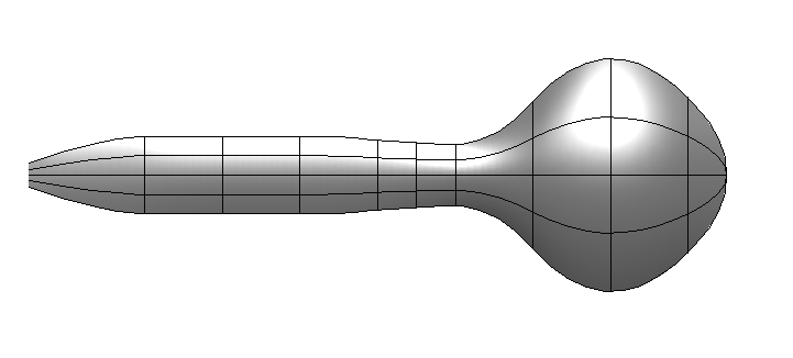
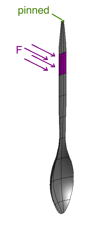
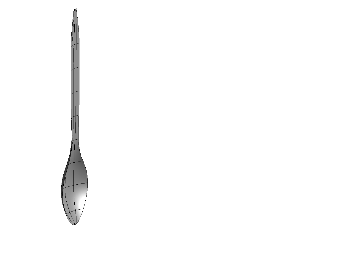
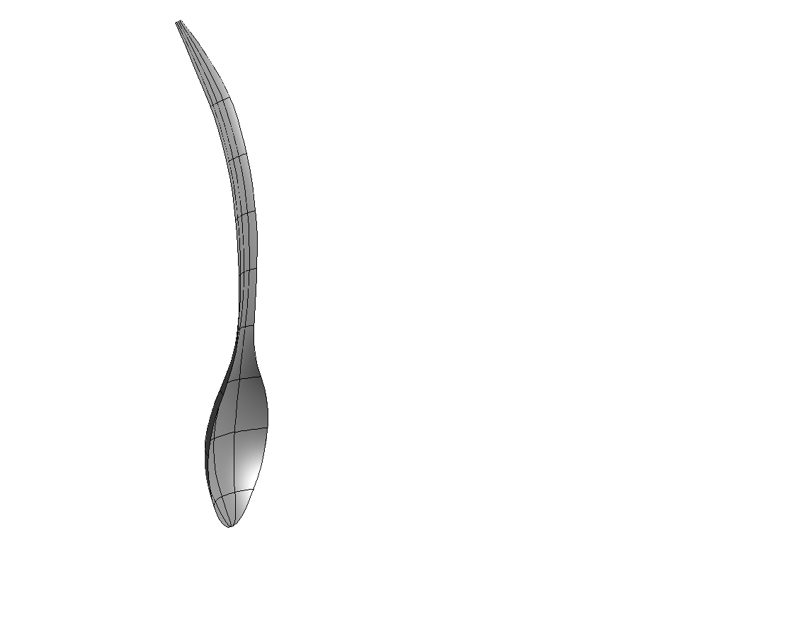
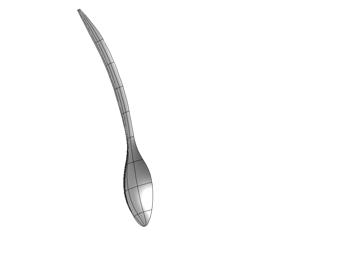
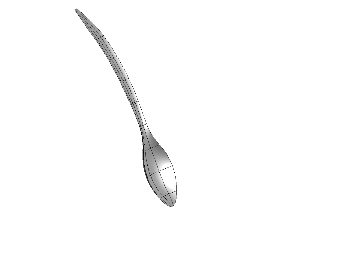
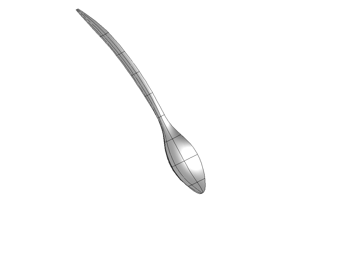
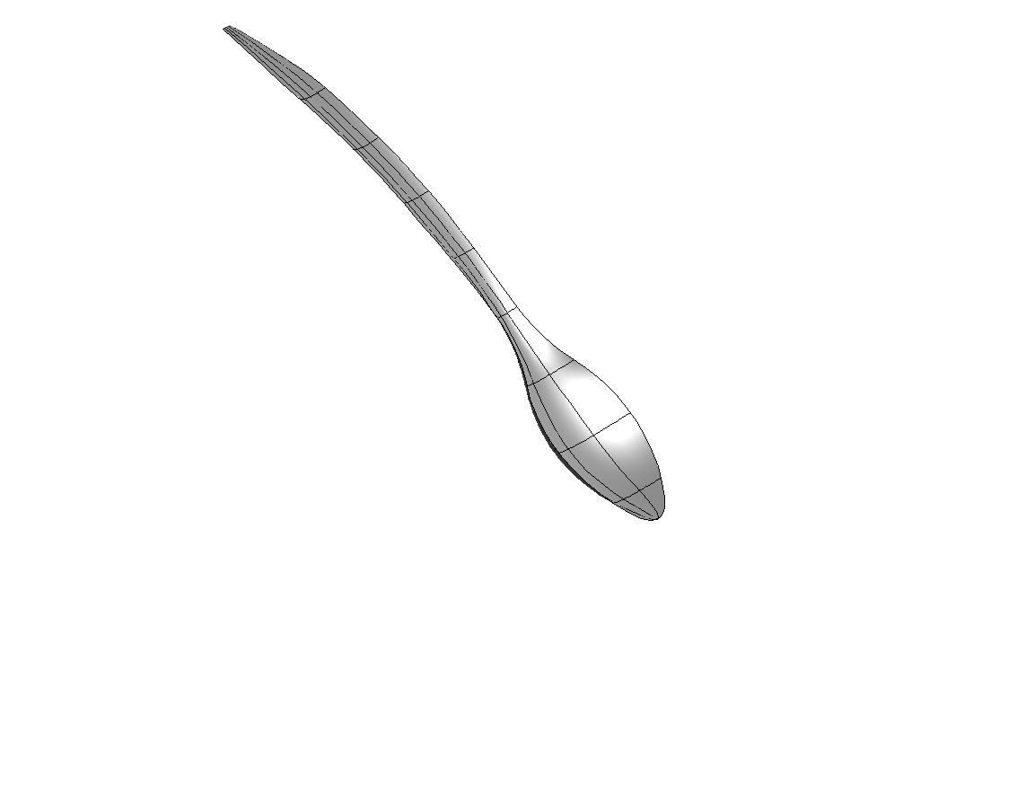
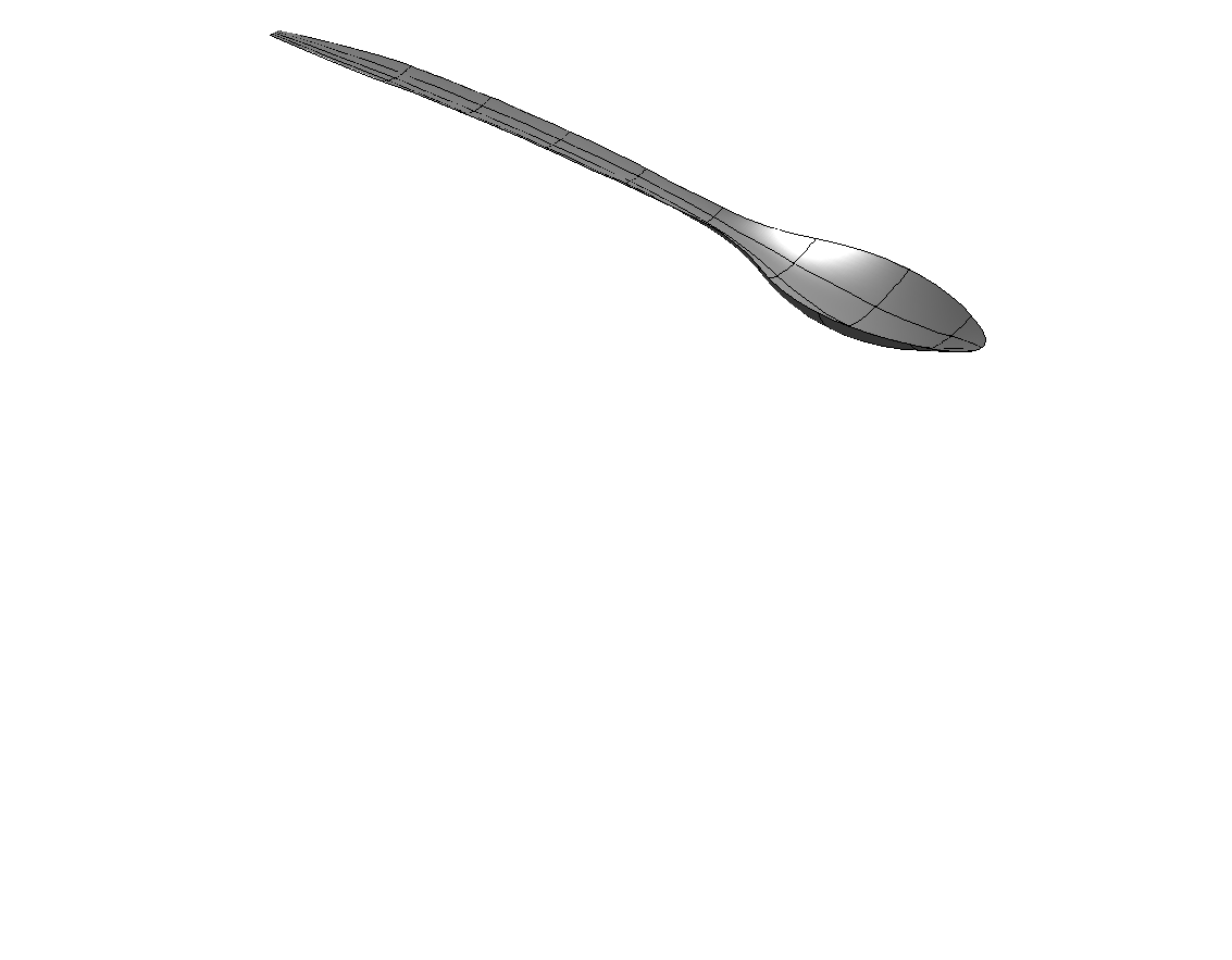
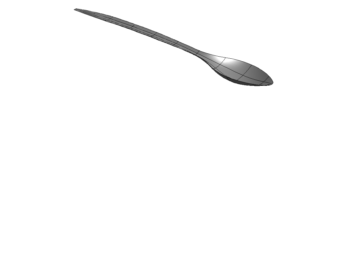
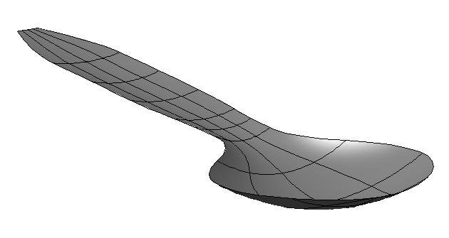
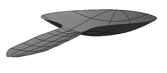
In this example, we model the fluid-structure interaction of a spoon moving through honey. The spoon geometry is shown in Figures 4 and 5, it is 4.5cm4.5𝑐𝑚4.5\,cm long with a thickness h=0.2mm0.2𝑚𝑚h=0.2\,mm and material parameters E=2.8109N/mm2,ν=0.39,ρ=1.13kg/m3formulae-sequence𝐸2.8superscript109𝑁𝑚superscript𝑚2𝐸2.8superscript109𝑁𝑚superscript𝑚2E=2.8\cdot 10^{9}\,N/mm^{2},\nu=0.39,\rho=1.13\,kg/m^{3}. The viscosity of the honey is taken as η=5.0Pas𝜂5.0𝑃𝑎𝑠\eta=5.0\,Pa\cdot s. The problem setup and boundary conditions are shown in Figure 5, with F=7000N/m2𝐹7000𝑁superscript𝑚2F=7000\,N/m^{2}, corresponding to a total load of 0.177N0.177𝑁0.177\,N. In Figure 6 the deformation at different time steps is displayed, where a time step of Δt=0.1sΔ𝑡0.1𝑠\Delta t=0.1\,s has been used. Figure 7 presents the details of the flow streamlines and velocity magnitude for two significant time steps.
Refer to caption
(a) t=1s𝑡1𝑠t=1s
Refer to caption
(b) t=51s𝑡51𝑠t=51s
Refer to caption
(c) t=101s𝑡101𝑠t=101s
Refer to caption
(d) t=151s𝑡151𝑠t=151s
Refer to caption
(e) t=201s𝑡201𝑠t=201s
Refer to caption
(f) t=251s𝑡251𝑠t=251s
Refer to caption
(g) t=301s𝑡301𝑠t=301s
Refer to caption
(h) t=351s𝑡351𝑠t=351s
Refer to caption
(i) t=401s𝑡401𝑠t=401s
Refer to caption
(j) t=451s𝑡451𝑠t=451s
Refer to caption
(k) t=501s𝑡501𝑠t=501s
Refer to caption
(l) t=551s𝑡551𝑠t=551s
Figure 8: Falling cap in water.
Refer to caption
(a) t=101s𝑡101𝑠t=101s
Refer to caption
(b) t=301s𝑡301𝑠t=301s
Figure 9: Falling cap streamline plots. Streamlines and velocity magnitude plots for the relative velocity, projected on two perpendicular planes. Velocity is measured in m/s𝑚𝑠m/s.

7.3 Falling cap

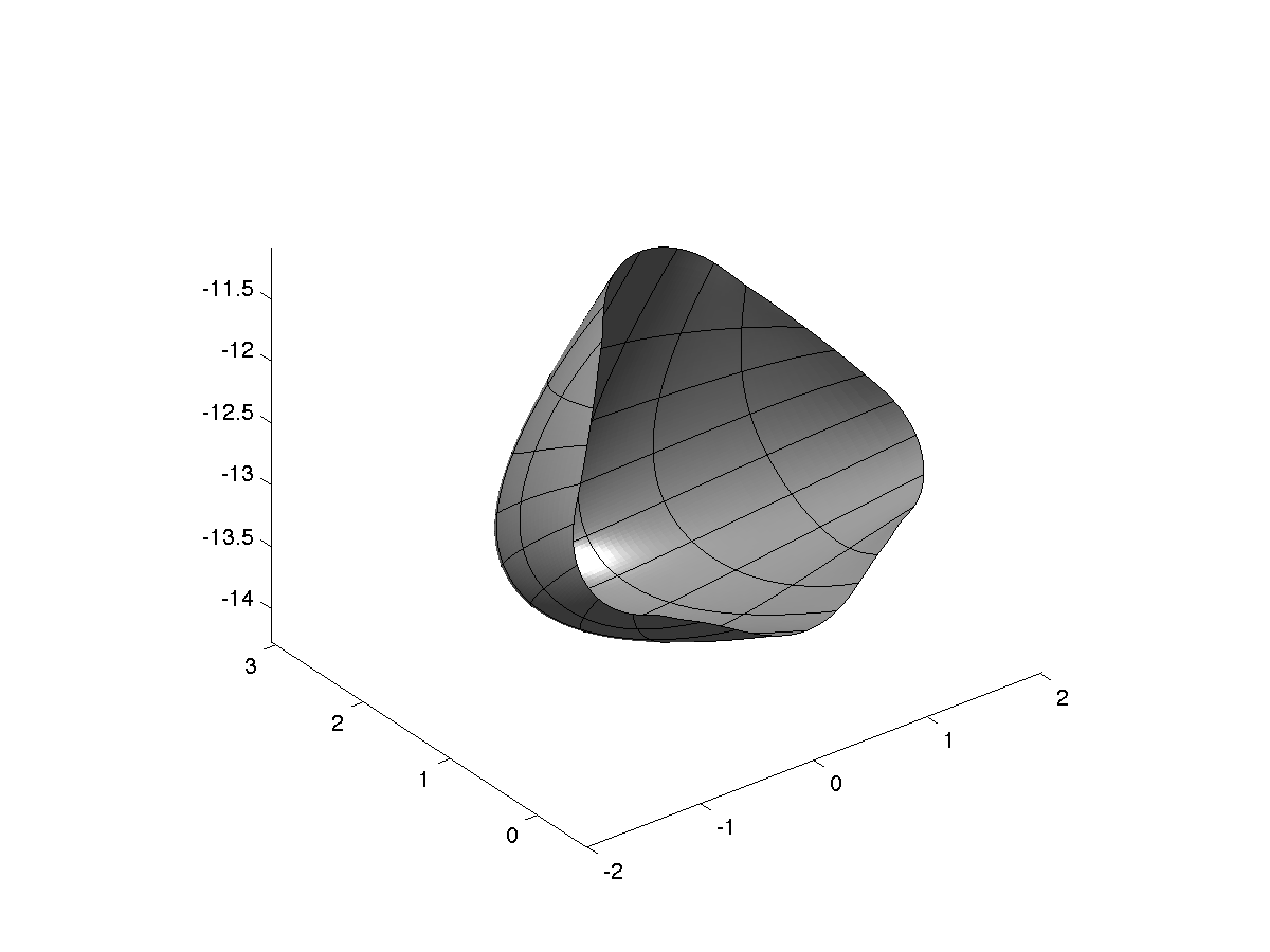
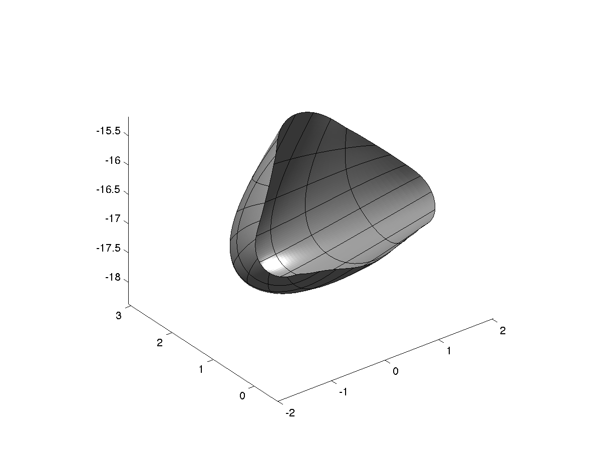
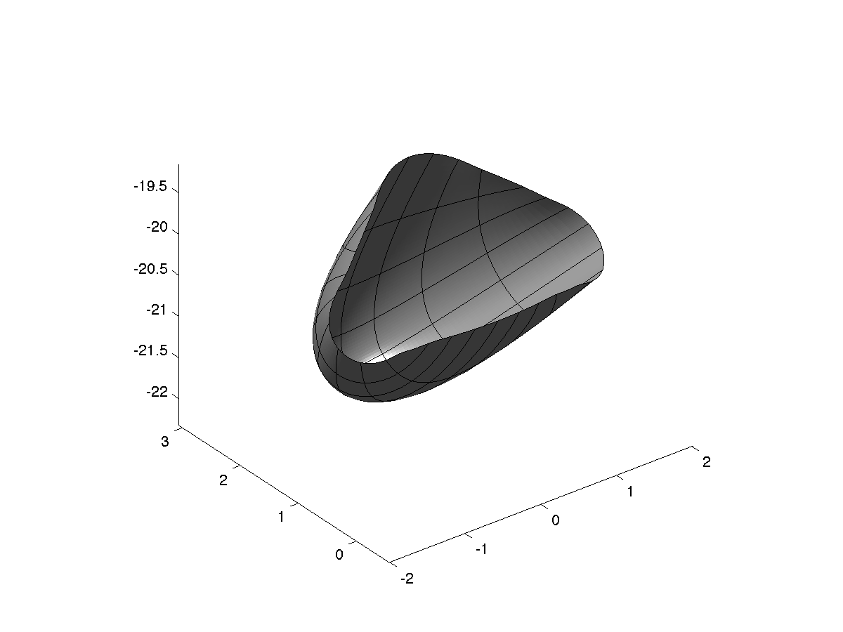
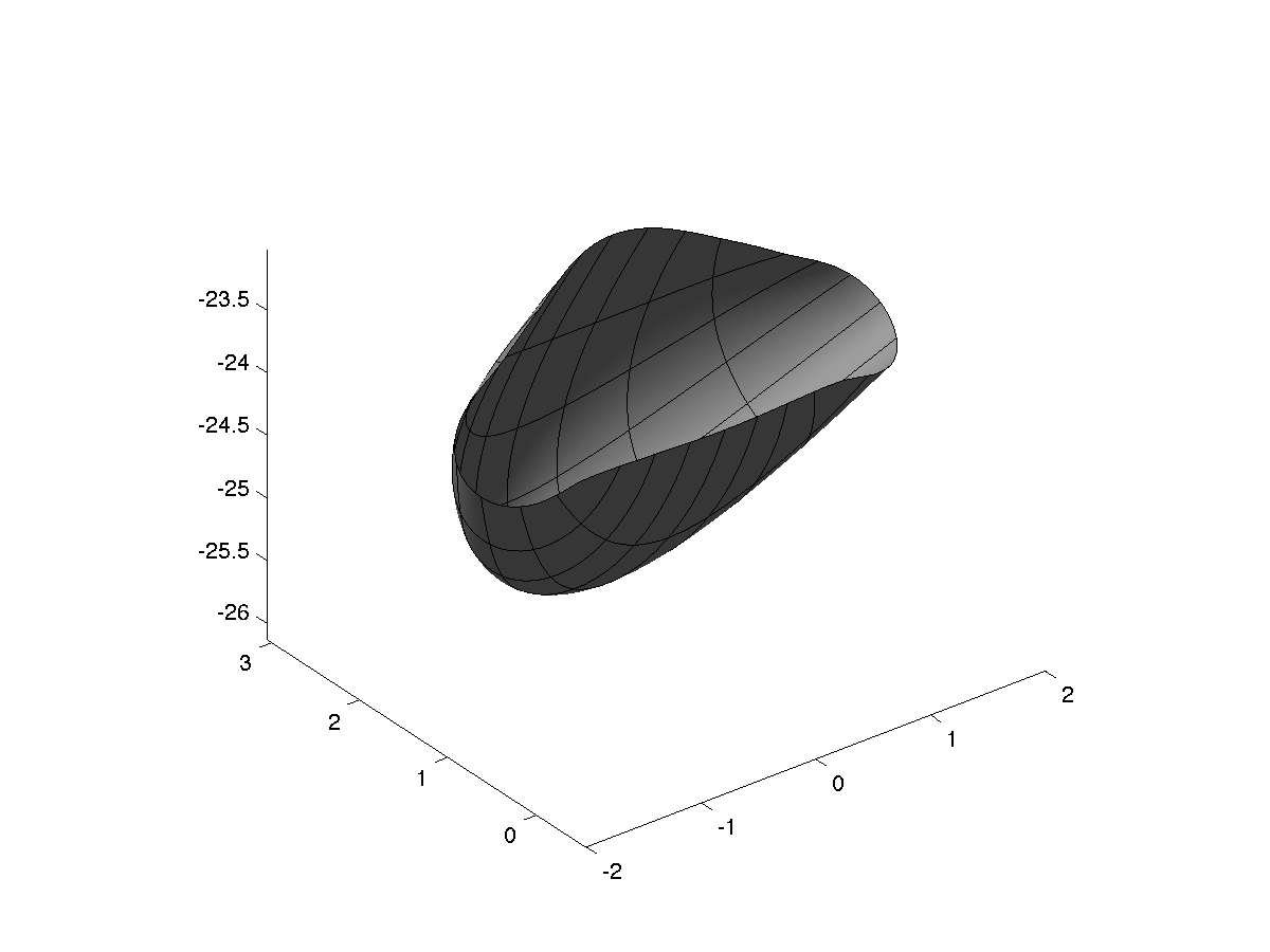
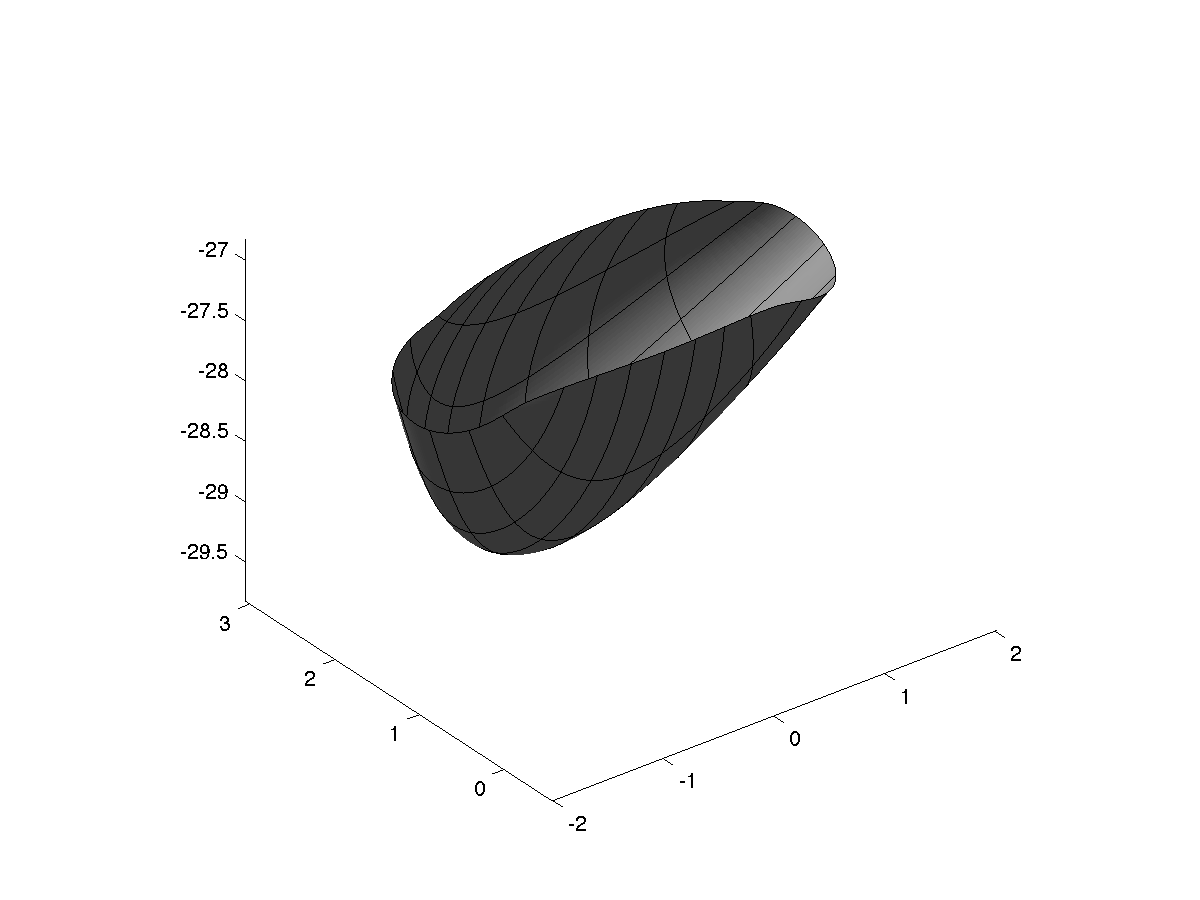
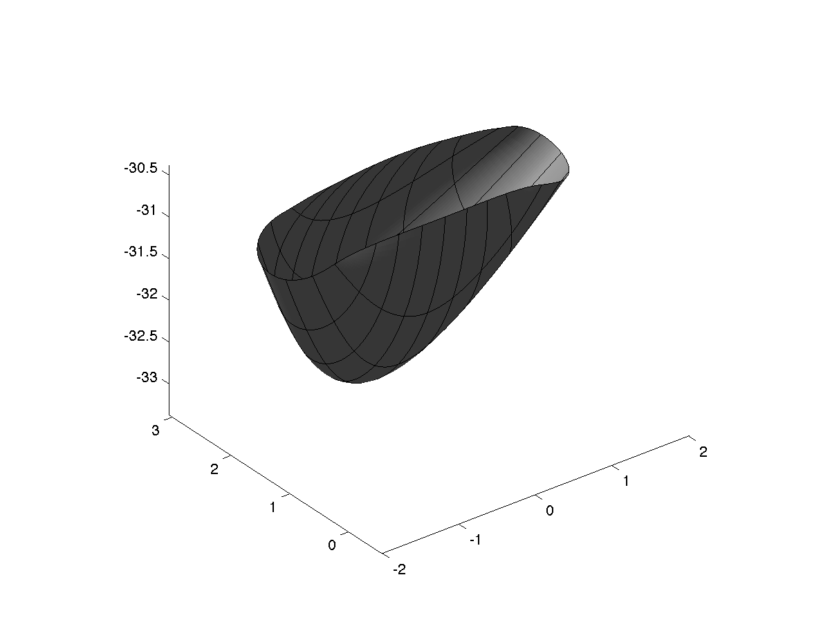
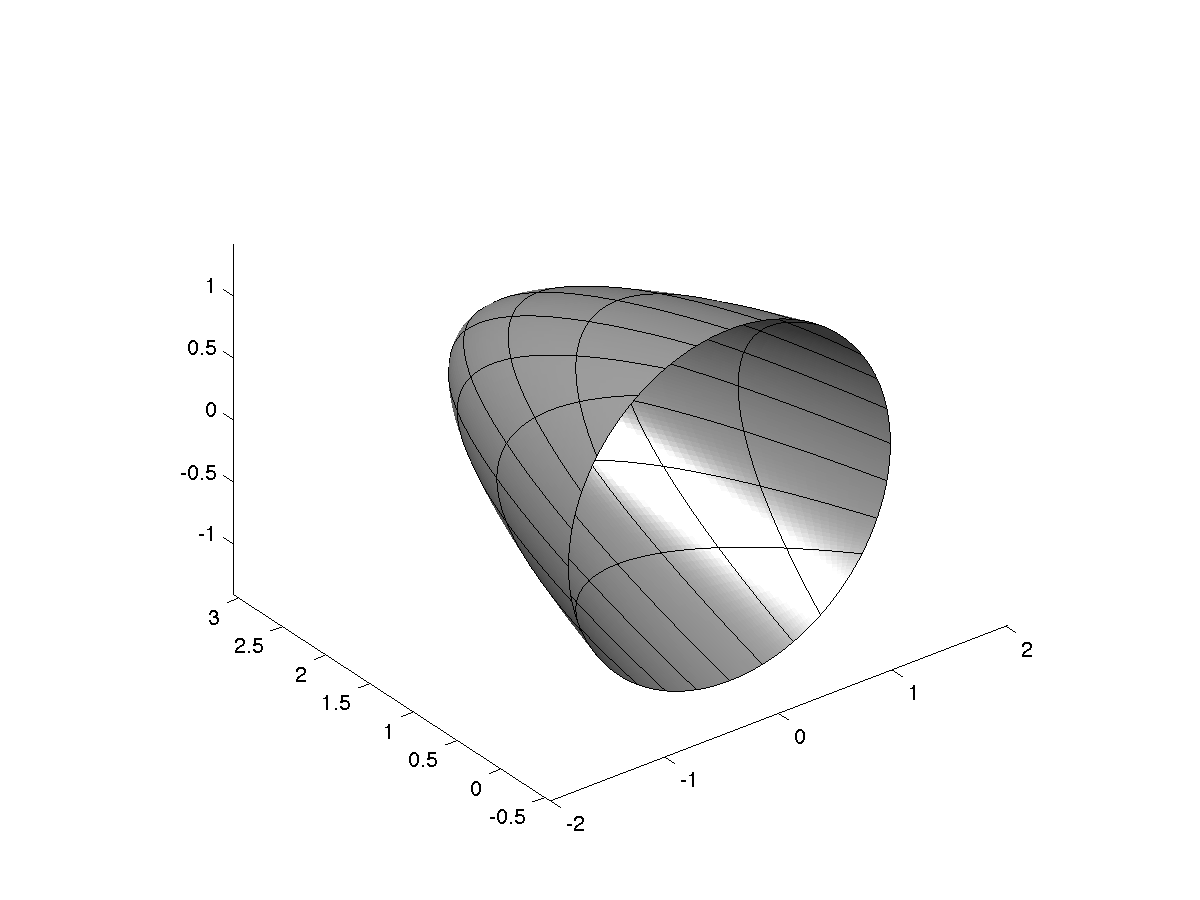
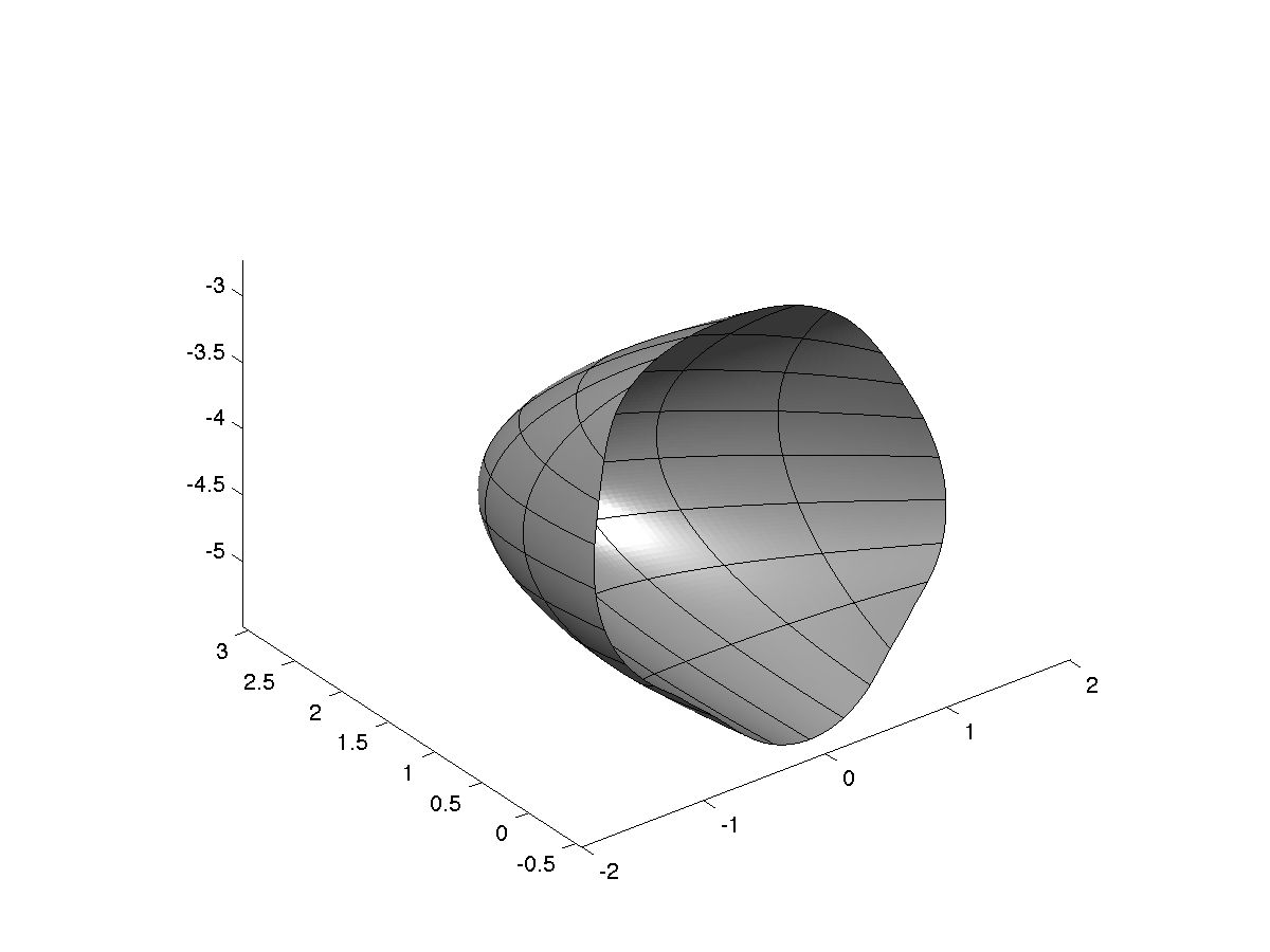
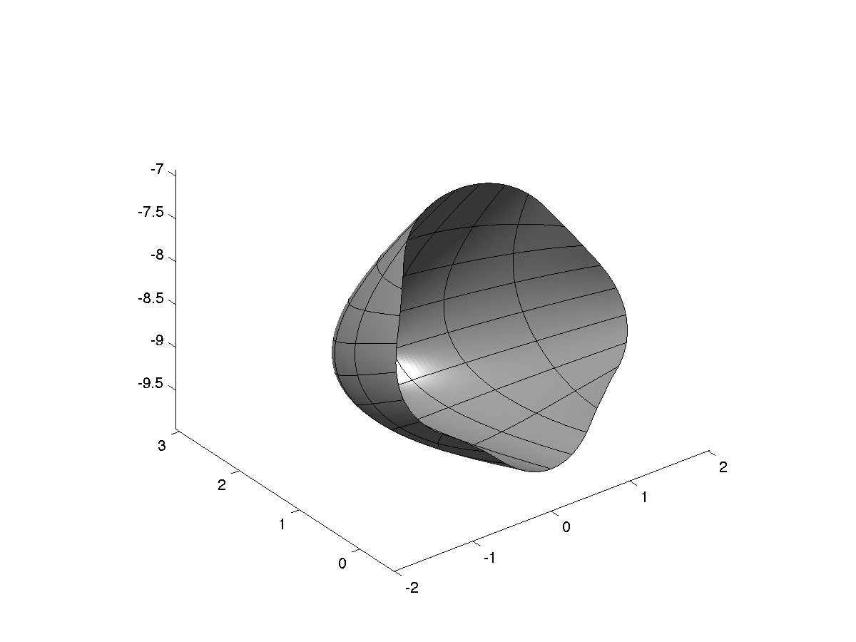
In this final example, we apply our method to the simulation of falling objects. Such problems are especially challenging in terms of fluid mesh generation and mesh update when using ALE approaches Franci2016520; Takizawa2012; Tezduyar2001. In casquero_nurbs_2015; Hesch201251; Zhang20042051, such problems were treated by immersed approaches, which avoid the difficulties of mesh update or remeshing but still require the discretization of a large fluid domain, whose size depends on the time interval to be observed. Using the approach presented in this paper, the computational domain is always confined to the surface model of the structure and is independent on the “falling time”. The object under consideration is a cap as shown in Figure 8(a). The structure’s material parameters are E=2.8105N/mm2,ν=0.39,ρ=1.13kg/m3formulae-sequence𝐸2.8superscript105𝑁𝑚superscript𝑚2𝐸2.8superscript105𝑁𝑚superscript𝑚2E=2.8\cdot 10^{5}\,N/mm^{2},\nu=0.39,\rho=1.13\,kg/m^{3} and the thickness is h=1.0mm1.0𝑚𝑚h=1.0\,mm. The structure is immersed into water with η=9.0103Pas𝜂9.0superscript103𝑃𝑎𝑠\eta=9.0\cdot 10^{-3}Pa\cdot s and subjected to gravity. A time step of Δt=1.0sΔ𝑡1.0𝑠\Delta t=1.0\,s is used for the analysis and the results are depicted in Figure 8. We can observe a combination of deformation modes, i.e., a rotation into the upright position and the deformation due to the flexibility of the structure. Figure 9 presents the details of the relative flow streamlines and relative velocity magnitude for two significant time steps.
8 Conclusions

In this paper, we have presented an isogeometric analysis framework to deal with a special class of FSI problems, where the fluid is represented by a Stokes flow and the structure by a shell. The proposed framework can be defined “truly isogeometric” because it is entirely based on bivariate geometries, as those immediately given by CAD B-rep descriptions, given the shell nature of the considered structure and the fact that the fluid equations are solved by isogeometric boundary elements. This allows to completely circumvent the mesh generation process in many situations. In addition, the use of boundary elements may significantly limit the dimension of the discrete problem, in particular when large fluid domains are studied as in the case of falling objects.

For the solution of the coupled problem, we have chosen to adopt a semi-implicit algorithm where the effect of the surrounding flow is incorporated in the non-linear terms of the solid solver through its damping characteristics. This strategy seems capable of favourably combining the accuracy and stability of a fully implicit method with the cost-efficiency of a segregated approach.

Several numerical tests have been presented, showing the potential of the proposed analysis framework. The extension to more complex situations, like, e.g., cell motion, and the study of the convergence properties of the model will be the subject of forthcoming research.

Acknowledgements

LH acknowledges support by the project OpenViewSHIP, “Sviluppo di un ecosistema computazionale per la progettazione idrodinamica del sistema elica-carena”, supported by Regione FVG - PAR FSC 2007-2013, Fondo per lo Sviluppo e la Coesione and by the project “TRIM - Tecnologia e Ricerca Industriale per la Mobilità Marina”, CTN01-00176-163601, supported by MIUR, the italian Ministry of Instruction, University and Research. Work by AR was supported by the European Research Council through the FP7 Ideas Starting Grant (project no. 259229) ISOBIO - Isogeometric Methods for Biomechanics, and work by ADS was supported by the European Research Council through AdG-340685– MicroMotility.

Appendix A Linearization of strain variables

We begin with the linearization of the displacement vector 𝒖𝒖\boldsymbol{u}{}, which, in discrete form, is defined as:

𝒖=ancpNa𝒖^a𝒖superscriptsubscript𝑎subscript𝑛𝑐𝑝superscript𝑁𝑎superscript^𝒖𝑎\displaystyle\boldsymbol{u}{}=\sum_{a}^{n_{cp}}N^{a}\hat{\boldsymbol{u}}^{a} (81)

where ncpsubscript𝑛𝑐𝑝n_{cp} is the number of control points, Nasuperscript𝑁𝑎N^{a} are the NURBS basis functions, and 𝒖^asuperscript^𝒖𝑎\hat{\boldsymbol{u}}^{a} are the nodal displacement vectors with components u^ia(i=1,2,3)subscriptsuperscript^𝑢𝑎𝑖𝑖123\hat{u}^{a}_{i}\,(i=1,2,3) referring to the global x,y,zlimit-from𝑥limit-from𝑥limit-from𝑥x-,y-,z-components. The global degree of freedom number 𝑰𝑰\boldsymbol{I} of a nodal displacement is defined by 𝑰=3(a1)+i𝑰3𝑎1𝑖\boldsymbol{I}=3(a-1)+i, such that u𝑰=u^iasubscript𝑢𝑰subscriptsuperscript^𝑢𝑎𝑖u_{\boldsymbol{I}}=\hat{u}^{a}_{i}. The variation with respect to u𝑰subscript𝑢𝑰u_{\boldsymbol{I}} is denoted by (),𝑰(\cdot),_{\boldsymbol{I}} for a compact notation and we obtain:

𝒖u𝑰=𝒖,𝑰=Na𝒆i\displaystyle\frac{\partial\boldsymbol{u}{}}{\partial u_{\boldsymbol{I}}}=\boldsymbol{u}{},_{\boldsymbol{I}}=N^{a}\boldsymbol{e}_{i} (82)

with 𝒆isubscript𝒆𝑖\boldsymbol{e}_{i} representing the global cartesian base vectors. For the second derivatives we obtain:

2𝒖u𝑰u𝑱=𝒖,𝑰𝑱=𝟎\displaystyle\frac{\partial^{2}\boldsymbol{u}{}}{\partial u_{\boldsymbol{I}}\partial u_{\boldsymbol{J}}}=\boldsymbol{u}{},_{\boldsymbol{I}\boldsymbol{J}}=\boldsymbol{0} (83)

Since variations with respect to u𝑰subscript𝑢𝑰u_{\boldsymbol{I}} vanish for all quantities of the undeformed configuration, we obtain for the variation of 𝒙𝒙\boldsymbol{x}:

𝒙,𝑰\displaystyle\boldsymbol{x},_{\boldsymbol{I}} =𝒖,𝑰=Na𝒆i\displaystyle=\boldsymbol{u}{},_{\boldsymbol{I}}=N^{a}\boldsymbol{e}_{i} (84)
𝒙,𝑰𝑱\displaystyle\boldsymbol{x},_{\boldsymbol{I}\boldsymbol{J}} =𝒖,𝑰𝑱=𝟎\displaystyle=\boldsymbol{u}{},_{\boldsymbol{I}\boldsymbol{J}}=\boldsymbol{0} (85)

Accordingly, we get the variations of the base vectors 𝒈αsubscript𝒈𝛼\boldsymbol{g}_{\alpha} as:

𝒈α,𝑰\displaystyle\boldsymbol{g}_{\alpha},_{\boldsymbol{I}} =N,αa𝒆i\displaystyle=N,_{\alpha}^{a}\boldsymbol{e}_{i} (86)
𝒈α,𝑰𝑱\displaystyle\boldsymbol{g}_{\alpha},_{\boldsymbol{I}\boldsymbol{J}} =𝟎absent0\displaystyle=\boldsymbol{0} (87)

and for 𝒈α,βsubscript𝒈𝛼𝛽\boldsymbol{g}_{\alpha,\beta}:

𝒈α,β,𝑰\displaystyle\boldsymbol{g}_{\alpha,\beta},_{\boldsymbol{I}} =N,αβa𝒆i\displaystyle=N,_{\alpha\beta}^{a}\boldsymbol{e}_{i} (88)
𝒈α,β,𝑰𝑱\displaystyle\boldsymbol{g}_{\alpha,\beta},_{\boldsymbol{I}\boldsymbol{J}} =𝟎absent0\displaystyle=\boldsymbol{0} (89)

With (86)-(87) and u𝑱=u^jbsubscript𝑢𝑱subscriptsuperscript^𝑢𝑏𝑗u_{\boldsymbol{J}}=\hat{u}^{b}_{j} we can express the variations of the metric coefficients gαβ=𝒈α𝒈βsubscript𝑔𝛼𝛽subscript𝒈𝛼subscript𝒈𝛽g_{\alpha\beta}=\boldsymbol{g}_{\alpha}\cdot\boldsymbol{g}_{\beta}:

gαβ,𝑰\displaystyle g_{\alpha\beta},_{\boldsymbol{I}} =N,αa𝒆i𝒈β+N,βa𝒆i𝒈α\displaystyle=N,_{\alpha}^{a}\boldsymbol{e}_{i}\cdot\boldsymbol{g}_{\beta}+N,_{\beta}^{a}\boldsymbol{e}_{i}\cdot\boldsymbol{g}_{\alpha} (90)
gαβ,𝑰𝑱\displaystyle g_{\alpha\beta},_{\boldsymbol{I}\boldsymbol{J}} =(N,αaN,βb+N,βaN,αb)δij\displaystyle=(N,_{\alpha}^{a}N,_{\beta}^{b}+N,_{\beta}^{a}N,_{\alpha}^{b})\delta_{ij} (91)

The variations of the unit normal vector 𝒈3subscript𝒈3\boldsymbol{g}_{3} are more involved and, therefore, we introduce the auxiliary variables 𝒈~3subscript~𝒈3\tilde{\boldsymbol{g}}_{3} and g3¯¯subscript𝑔3\bar{g_{3}}

𝒈~3=𝒈1×𝒈2subscriptbold-~𝒈3subscript𝒈1subscript𝒈2\boldsymbol{\tilde{g}}_{3}=\boldsymbol{g}_{1}\times\boldsymbol{g}_{2} (92)
g¯3=𝒈~3𝒈~3subscript¯𝑔3subscriptbold-~𝒈3subscriptbold-~𝒈3\bar{g}_{3}=\sqrt{\boldsymbol{\tilde{g}}_{3}\cdot\boldsymbol{\tilde{g}}_{3}} (93)

such that 𝒈3subscript𝒈3\boldsymbol{g}_{3} can be written as:

𝒈3=𝒈~3g¯3subscript𝒈3subscriptbold-~𝒈3subscript¯𝑔3\boldsymbol{g}_{3}=\frac{\boldsymbol{\tilde{g}}_{3}}{\bar{g}_{3}} (94)

In the following, we first compute the variations of the auxiliary variables which are then used for further derivations. It is convenient to follow this approach also in the implementation since these intermediate results are needed several times. We first derive the variations of 𝒈~3subscript~𝒈3\tilde{\boldsymbol{g}}_{3}:

𝒈~3,𝑰\displaystyle\boldsymbol{\tilde{g}}_{3},_{\boldsymbol{I}} =𝒈1,𝑰×𝒈2+𝒈1×𝒈2,𝑰\displaystyle=\boldsymbol{g}_{1},_{\boldsymbol{I}}\times\,\boldsymbol{g}_{2}+\boldsymbol{g}_{1}\times\boldsymbol{g}_{2},_{\boldsymbol{I}} (95)
𝒈~3,𝑰𝑱\displaystyle\boldsymbol{\tilde{g}}_{3},_{\boldsymbol{I}\boldsymbol{J}} =𝒈1,𝑰×𝒈2,𝑱+𝒈1,𝑱×𝒈2,𝑰\displaystyle=\boldsymbol{g}_{1},_{\boldsymbol{I}}\times\,\boldsymbol{g}_{2},_{\boldsymbol{J}}+\boldsymbol{g}_{1},_{\boldsymbol{J}}\times\boldsymbol{g}_{2},_{\boldsymbol{I}} (96)

which are used for the variations of g¯3subscript¯𝑔3\bar{g}_{3}:

g¯3,𝑰\displaystyle\bar{g}_{3},_{\boldsymbol{I}} =𝒈3𝒈~3,𝑰\displaystyle=\boldsymbol{g}_{3}\cdot\boldsymbol{\tilde{g}}_{3},_{\boldsymbol{I}} (97)
g¯3,𝑰𝑱\displaystyle\bar{g}_{3},_{\boldsymbol{I}\boldsymbol{J}} =g¯31(𝒈~3,𝑰𝑱𝒈~3+𝒈~3,𝑰𝒈~3,𝑱(𝒈~3,𝑰𝒈3)(𝒈~3,𝑱𝒈3)\displaystyle=\bar{g}_{3}^{-1}(\boldsymbol{\tilde{g}}_{3},_{\boldsymbol{I}\boldsymbol{J}}\cdot\boldsymbol{\tilde{g}}_{3}+\boldsymbol{\tilde{g}}_{3},_{\boldsymbol{I}}\cdot\boldsymbol{\tilde{g}}_{3},_{\boldsymbol{J}}-(\boldsymbol{\tilde{g}}_{3},_{\boldsymbol{I}}\cdot\boldsymbol{g}_{3})(\boldsymbol{\tilde{g}}_{3},_{\boldsymbol{J}}\cdot\boldsymbol{g}_{3}) (98)

and finally for the variations of 𝒈3subscript𝒈3\boldsymbol{g}_{3}:

𝒈3,𝑰\displaystyle\boldsymbol{g}_{3},_{\boldsymbol{I}} =g¯31(𝒈~3,𝑰g¯3,𝑰𝒈3)\displaystyle=\bar{g}_{3}^{-1}(\boldsymbol{\tilde{g}}_{3},_{\boldsymbol{I}}-\bar{g}_{3},_{\boldsymbol{I}}\boldsymbol{g}_{3}) (99)
𝒈3,𝑰𝑱\displaystyle\boldsymbol{g}_{3},_{\boldsymbol{I}\boldsymbol{J}} =g¯31(𝒈~3,𝑰𝑱g¯3,𝑰𝑱𝒈3)+g¯32(2g¯3,𝑰g¯3,𝑱𝒈3g¯3,𝑰𝒈~3,𝑱g¯3,𝑱𝒈~3,𝑰)\displaystyle=\bar{g}_{3}^{-1}(\boldsymbol{\tilde{g}}_{3},_{\boldsymbol{I}\boldsymbol{J}}-\bar{g}_{3},_{\boldsymbol{I}\boldsymbol{J}}\boldsymbol{g}_{3})+\bar{g}_{3}^{-2}(2\bar{g}_{3},_{\boldsymbol{I}}\bar{g}_{3},_{\boldsymbol{J}}\boldsymbol{g}_{3}-\bar{g}_{3},_{\boldsymbol{I}}\boldsymbol{\tilde{g}}_{3},_{\boldsymbol{J}}-\bar{g}_{3},_{\boldsymbol{J}}\boldsymbol{\tilde{g}}_{3},_{\boldsymbol{I}}) (100)

With (88)-(89) and (99)-(100), we can compute the variations of the curvatures bαβ=𝒈α,β𝒈3subscript𝑏𝛼𝛽subscript𝒈𝛼𝛽subscript𝒈3b_{\alpha\beta}=\boldsymbol{g}_{\alpha,\beta}\cdot\boldsymbol{g}_{3}:

bαβ,𝑰\displaystyle b_{\alpha\beta},_{\boldsymbol{I}} =𝒈α,β,𝑰𝒈3+𝒈α,β𝒈3,𝑰\displaystyle=\boldsymbol{g}_{\alpha},_{\beta},_{\boldsymbol{I}}\,\boldsymbol{g}_{3}+\boldsymbol{g}_{\alpha},_{\beta}\,\boldsymbol{g}_{3},_{\boldsymbol{I}} (101)
bαβ,𝑰𝑱\displaystyle b_{\alpha\beta},_{\boldsymbol{I}\boldsymbol{J}} =𝒈α,β,𝑰𝒈3,𝑱+𝒈α,β,𝑱𝒈3,𝑰+𝒈α,β𝒈3,𝑰𝑱\displaystyle=\boldsymbol{g}_{\alpha},_{\beta},_{\boldsymbol{I}}\boldsymbol{g}_{3},_{\boldsymbol{J}}+\boldsymbol{g}_{\alpha},_{\beta},_{\boldsymbol{J}}\boldsymbol{g}_{3},_{\boldsymbol{I}}+\boldsymbol{g}_{\alpha},_{\beta}\boldsymbol{g}_{3},_{\boldsymbol{I}\boldsymbol{J}} (102)

With equations (88)-(89) and (101)-(102) we finally obtain the variations the strain variables:

εαβ,𝑰\displaystyle\varepsilon_{\alpha\beta},_{\boldsymbol{I}} =12(gαβGαβ),𝑰=12gαβ,𝑰\displaystyle=\frac{1}{2}(g_{\alpha\beta}-G_{\alpha\beta}),_{\boldsymbol{I}}=\frac{1}{2}g_{\alpha\beta},_{\boldsymbol{I}} (103)
εαβ,𝑰𝑱\displaystyle\varepsilon_{\alpha\beta},_{\boldsymbol{I}\boldsymbol{J}} =12gαβ,𝑰𝑱\displaystyle=\frac{1}{2}g_{\alpha\beta},_{\boldsymbol{I}\boldsymbol{J}} (104)
καβ,𝑰\displaystyle\kappa_{\alpha\beta},_{\boldsymbol{I}} =(Bαβbαβ),𝑰=bαβ,𝑰\displaystyle=(B_{\alpha\beta}-b_{\alpha\beta}),_{\boldsymbol{I}}=-b_{\alpha\beta},_{\boldsymbol{I}} (105)
καβ,𝑰𝑱\displaystyle\kappa_{\alpha\beta},_{\boldsymbol{I}\boldsymbol{J}} =bαβ,𝑰𝑱\displaystyle=-b_{\alpha\beta},_{\boldsymbol{I}\boldsymbol{J}} (106)

Appendix B

Conversion to HTML had a Fatal error and exited abruptly. This document may be truncated or damaged.