Clamped seismic metamaterials: Ultra-low broad frequency stop-bands
Abstract
The regularity of earthquakes, their destructive power, and the nuisance of ground vibration in urban environments, all motivate designs of defence structures to lessen the impact of seismic and ground vibration waves on buildings. Low frequency waves, in the range to Hz for earthquakes and up to a few tens of Hz for vibrations generated by human activities, cause a large amount of damage, or inconvenience; depending on the geological conditions they can travel considerable distances and may match the resonant fundamental frequency of buildings. The ultimate aim of any seismic metamaterial, or any other seismic shield, is to protect over this entire range of frequencies; the long wavelengths involved, and low frequency, have meant this has been unachievable to date.
Elastic flexural waves, applicable in the mechanical vibrations of thin elastic plates, can be designed to have a broad zero-frequency stop-band using a periodic array of very small clamped circles. Inspired by this experimental and theoretical observation, all be it in a situation far removed from seismic waves, we demonstrate that it is possible to achieve elastic surface (Rayleigh) and body (pressure P and shear S) wave reflectors at very large wavelengths in structured soils modelled as a fully elastic layer periodically clamped to bedrock. We identify zero frequency stop-bands that only exist in the limit of columns of concrete clamped at their base to the bedrock. In a realistic configuration of a sedimentary basin 15 meters deep we observe a zero frequency stop-band covering a broad frequency range of to Hz.
1 Introduction
The desire to deflect, absorb or redirect waves is ubiquitous across many fields: electromagnetics, optics, hydrodynamics, acoustics and elasticity. Various techniques have been developed, often in one field but not in the others, and we are going to draw upon advances in optics and electromagnetic wave systems to develop a methodology for reflecting long-wavelength seismic waves in sedimentary basins. The motivations to do so are clear: According to the US Geological Survey there are millions of earthquakes every year worldwide, the vast majority are magnitude 3.9 or lower but more than 1000 measure 5.0 or higher on the Richter scale [1]. Ground vibrations, caused by even minor earthquakes, have an impact upon the structural integrity of buildings and similarly intrusive ground vibrations from urban train systems, subways, machinery such as piledrivers and roads often affect property values or land usage. These vibrations are not simply a nuisance, but small magnitude vibration due to machinery, or nearby railway lines, can cause significant damage to buildings, especially over time [2]. Furthermore, for buildings such as nuclear power plants and oil refineries, even a small level of damage can have disastrous consequences. Seismic waves consist of surface waves (elliptically polarized Rayleigh waves and horizontally polarized Love waves), pressure bulk waves and shear bulk waves; surface waves cause the majority of any damage and travel farthest, but bulk pressure, and shear, waves also cause damage, especially where wave trapping occurs in sedimentary basins (so-called seismic site effects). Designing a defence structure to prevent seismic waves from reaching buildings is therefore of substantial interest particularly for long waves with frequency in the range to Hz as this corresponds to the resonant fundamental frequency of many man-made structures [3]. It is, of course, these long, low frequency, waves that are the hardest to develop protection measures against and it is an open problem to develop such devices.
Since the late 1980s, in optics, researchers have taken advantage of technological improvements in structuring matter to achieve control over the flow of light [4, 5]. The photonic crystals typically used are periodic man-made structures that inhibit emission due to band gaps [6, 7], i.e., ranges of frequency in which light cannot propagate through the structure. The existence of stop-bands is well predicted by Floquet-Bloch theory, which can be applied to any type of waves propagating within periodic media [8, 9, 10]. Importantly, for practical implementation, periodicity need not be perfect to preserve existence of stop-bands [11]. For such periodic structures, striking effects such as slow light can be achieved on edges of stop-bands where the wave group velocity vanishes [12]. More recently the field of metamaterials has emerged that uses periodic arrangements of elements with size much smaller than the considered wavelength (typically hundreds of nanometers) that acquire effective properties of materials with negative optical index [13, 14], or highly anisotropic materials such as hyperbolic metamaterials [15] or can be used to create invisibility cloaking devices [16, 17].
These ideas have been translated to acoustics and the corresponding acoustic phononic crystals have had success with early work by Sigalas and Economou [18] showing that an infinite 2D array of high-density parallel cylinders embedded in a low-density host material possesses a complete band gap in two dimensions; these effects are beautifully illustrated by the sound attenuation through a sculpture by artist Eusebio Sempere [19], that exhibits partial stop-bands from to kHz, which has had impact both on the scientific community and the general public. Aside from acoustics, these ideas have had applications in other wave systems such as proposed breakwater devices, Hu and Chan [20], for surface ocean waves as a potential application of photonic crystals at the meter-scale. In the same spirit, some of us envisioned rerouting ocean waves around a region of still water surrounded by concentric arrays of pillars [21]; non-overtopping dykes for ocean waves can be also envisaged with meter scale invisibility carpets for water waves [22, 23].
Elastic phononic crystals can also be envisaged and typically fall into studies of flexural thin elastic plates, bulk media or surface waves atop thick elastic substrates; the latter supporting Rayleigh surfaces waves. There are close analogies with electromagnetic surface waves, as an example, surface plasmons which have features close to those of Rayleigh waves at least qualitatively. [24] showed the existence of Rayleigh-Bloch waves in linear periodic gratings for flexural waves and these also appear in the full elastodynamic setting [25]. These Rayleigh-Bloch waves are waves localised to the grating, exponentially decaying away from the grating, and only exist due to the periodicity, these have direct parallels to spoof plasmons in the field of plasmonics, which is devoted to the control of surface electromagnetic waves in structured metals [26, 27]. Thus qualitatively ideas from electromagnetism transfer to the elastic cases and can act as strong motivation.
This activity has motivated experiments on the control of surface acoustic waves on the microscale in phononic crystals, with holes, have been performed by Benchabane et al. [28] and extended to the hypersonic regime [29]. Protrusions such as pillars atop an elastic substrate have also been considered [30, 31] inspiring studies using negative refraction for Rayleigh [32] and Lamb [33, 34, 35] waves. Such interactions between resonators on the surface, or surface defects, and surface waves have found widespread application in phononic membranes [36] and in interrogating the contact adhesion of microspheres [37] to name but a few. Interestingly, the existence of a zero-frequency stop-band in periodically pinned plates was proposed to shield Lamb waves of very large wavelengths in [35], whereas experiments with arrays of thin elastic rods atop thin plates showed deeply subwavelength shielding and localization effects in [38]. These lead one to consider the implications on large-scale, i.e. meters, in terms of geophysics.
Returning to seismic waves and ground vibration, Rayleigh wave attenuation was achieved back in 1999 [39] in a marble quarry with air holes displaying kHz stop-bands; this is at a frequency range far higher than that required by the seismic application. The theoretical concept of a seismic 2D grid of inclusions in the soil interacting with a part of the earthquake signal was first created in the experiments of [40] and from hereon we too envisage a 1D or 2D phononic crystal as a 1D or 2D structured soil (natural or artificial). In 2012, with the aim of demonstrating the feasibility of the concept with field data, full-scale seismic tests were held by the Ménard company in France using a grid of vertical empty cylindrical holes with a 50 Hz source [40] that falls in the partial stop-band of the large-scale phononic crystal. This is, again, still too high for seismic applications, ideally one desires a zero-frequency stop-band structure capable of attenuating long-waves at very low frequencies. Interestingly, Miniaci et al. [41] propose using cross-shaped, hollow and locally resonant (with rubber, steel and concrete), cylinders to attenuate both Rayleigh and bulk waves in the 1 to 10 Hz frequency range. Unfortunately, the main drawback of this type of locally resonant structure is the difficulty in obtaining very large efficient stop bands; there is always a trade-off between the relative bandwidth and the efficiency of the attenuation, which is directly linked to the quality factor of the resonators. The frequency bandwidth of wave protection can be enlarged by considering arrays of resonant cylinders with different eigenfrequency for two-dimensional stop-bands [42], or cubic arrays of resonant spheres [43] for 3D stop-bands, but such mechanical metamaterials would be hard to implement at the civil engineering scale. Buried isochronous mechanical oscillators have been also envisaged to filter the S waves of earthquakes [44]. A complementary approach employed in [45, 46] is to draw upon the metamaterials literature that utilises subwavelength resonators arranged, in their case, upon the surface of an elastic half-space; this results in surface to bulk wave conversion, and surface wave filters with band-gaps but again at higher frequency than those required for seismic protection.
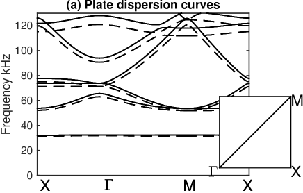
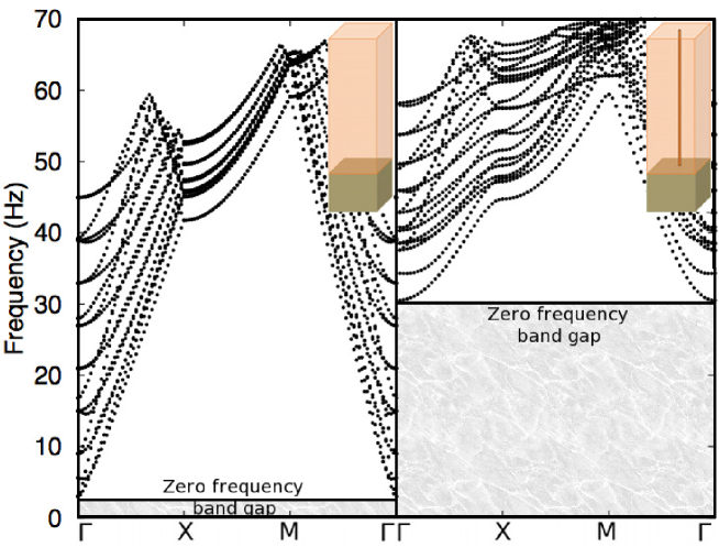
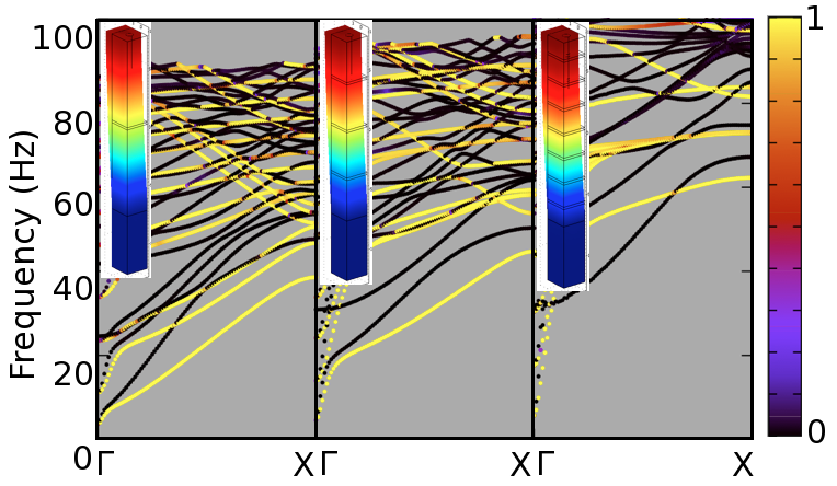
Identifying that the main objective of a seismic metamaterial must be to achieve a broad low-frequency stop-band, or even better a zero-frequency stop-band, we turn to the apparently, distantly connected, field of thin elastic structured plates; these are of interest in terms of flexural waves connected with the vibration of shells. The simplest model, the thin plate model of Kirchhoff and Love is well-known [47, 48] and is a fourth-order scalar partial differential equation for the vertical displacement; this is a dramatic simplification over the full vector elastic system [49] and, for homogeneous plates, this simpler model is, in theory, valid for very thin plates with a thickness less than of the typical wavelength [50]. None the less surprising accuracy can be obtained in structured plates, where this thickness restriction can be relaxed, and recent detailed comparison of theory and experiment [51] demonstrate that conclusions from the Kirchhoff-Love (K-L) theory carry across into thin plate modelling even at much higher frequencies where it might naively be thought to be invalid (typically in practice a plate thickness less that th of the wavelength provides good approximations for homogeneous plates); Fig. 1 shows dispersion curves from K-L theory alongside those of full-elasticity, both sets calculated using finite element (FE) software [52]. These are shown for a structured plate consisting of small clamped circular regions (mm radius) arranged on a square lattice of pitch cm and for a 0.5mm thick plate of duraluminium ( kg/m3, GPa, ). An important, indeed critical for our purposes here, observation, is that this system has a zero-frequency stop-band. As noted earlier there is close correspondence of full vector elastic calculations with those from K-L theory far outside the range of frequencies one might usually associate with thin plate K-L theory; the reason, as noted, in [51] is that what actually matters is not a constraint from homogeneous plates, but how the wavelengths in the periodic structured system compare to the plate thickness and they are actually large. Fig. 1 takes advantage of the periodicity of the structured elastic plate, as is well-known in solid state physics [53] Bloch’s theorem means that, for an infinite array, one need only consider the wavenumbers in the irreducible Brillouin zone (IBZ) which, for a square lattice, are those in the triangle (, , ) shown as the inset to Fig. 1(a) and for clarity we show the frequency dependence versus wavenumbers going around the edges of the IBZ. We will exclusively use square lattices in this article and comment upon other lattice geometries in section 3 (see also Fig. 10).
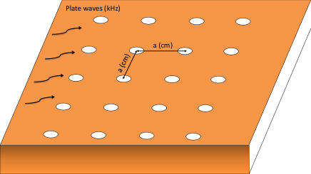
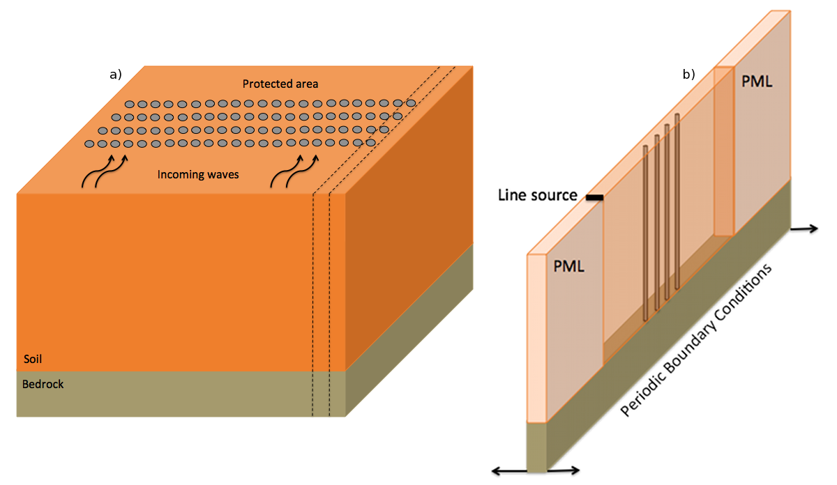
Having successfully identified a scenario, all be it in a different situation of thin elastic plates far removed from the seismic application of thick elastic substrates, giving a zero-frequency band gap we use this to design a seismic metamaterial to have these characteristics [54]. The aim of this article is to investigate structuring soil, as shown in Fig. 2, to protect a building or portion of the surface. The structuration consists of columns, in a layer of soil, that are clamped to underlying bedrock; the columns are arranged in a periodic fashion. The key difference from all previous studies is that, motivated by thin plate calculations of Fig. 1 and the resultant zero frequency band gap, we consider the influence of clamping columns to the bedrock.
2 Results
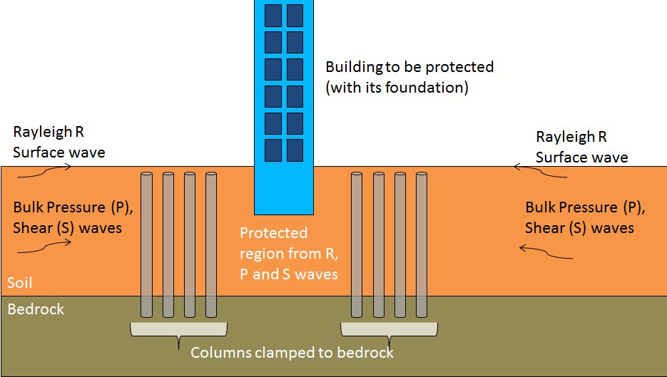
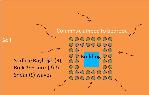
We note that many seismic applications such as ground reinforcement, concern layers of softer soils overlying more solid bedrock and modern civil engineering processes allow columns to be clamped, that is, rigidly attached, to the bedrock [55]. The layers are no longer thin enough to employ K-L thin plate theory and the effect of depth (equivalently thickness of the plate) is now important. We explore the potential of seismic metamaterial devices shown in Fig. 2; the side view shows a structure atop a soil layer of finite thickness that overlays the bedrock; columns clamped to the bedrock puncture the soil layer and reach to the surface, or close to surface, a top view shows the array of columns encircling the building to be protected.
We consider small strain seismicity, [56], with a rate of deformation ( such that ), in this situation the duration of seismic disturbance, for this type of earthquake, is sufficiently short to accept the hypothesis of elastic behaviour for the soil. We can therefore take realistic soil, rock and depth parameters from geophysics with the Young’s modulus, , of the soil and rock being MPa and GPa respectively, Poisson ratios of for both and density of the soil and rock being kg/m3 and kg/m3 respectively. A typical depth of soil is m, which overlays bedrock of depth m with effectively rigid material beneath it (i.e. the bedrock interface is modelled with Dirichlet boundary data, which is zero displacement there).
Given the geometric and physical complexity we proceed to numerical simulations. For these simulations we solve the elastic Navier equation [57] with time-harmonic motion considered at fixed frequency i.e. in the absence of any sources we consider
| (1) |
where is an isotropic symmetric rank-4 elasticity tensor, with spatially varying entries written in a Cartesian basis , with the Kronecker symbol and the bulk modulus, the shear modulus, the density, the angular wave frequency and the 3 component displacement field. We discretize the weak form of (1) using finite element methods and in particular we utilise COMSOL [52]. For band structure calculations, we take advantage of the periodicity of the system in the horizontal -plane to consider a single elementary cell. For this we use the Bloch-Floquet theorem i.e. we assume that solutions of (1) are such that
| (2) |
where is the lattice vector of the 2D array of columns and is the Bloch (or momentum) wavevector in 2D reciprocal space (both and lie in the horizontal plane).
We then construct, and solve, the eigenvalue problem created by substituting the Bloch wave form in (1); this leads to the eigenvalue problem for the shifted Navier operator :
| (3) |
where parameterized by , which relates the phase shift across the cell to the frequency (see [58] for the electromagnetic case). For a given , one gets a discrete set of eigenfrequencies tending to infinity as the operator in (3) has a compact resolvent. Since the eigenfrequencies are continuous with respect to , when varies in the Brillouin zone , the so-called Bloch band spectrum is found
| (4) |
see for instance [9, 5]. The dispersion surfaces computed are critical in guiding our understanding of the Bloch wave behaviour, we refer to [51] for structured media displaying elliptic, parabolic and hyperbolic shapes of dispersion surfaces leading to extreme elastic wave control at certain frequencies revealed by so-called High-Frequency Homogenization [59]. Importantly, when , the quasi-static limit of the band spectrum allows one to deduce effective properties of the periodic structure (such as anisotropy) through the slope or curvature of dispersion surfaces in the neighbourhood of point [60, 9] depending upon whether they have a conical or parabolic shape. One can then interpret the effective behaviour of the low frequency Bloch waves in terms of their effective group velocity, or effective mass [61]. However, when some Dirichlet data, , is set on some domain within the IBZ, corresponding to a clamped (possibly very small) inclusion, one infers from the maximum principle [60, 9] that is null everywhere in the IBZ, and is not an admissible eigenfield. Hence . This seemingly minor remark has important practical consequences: it shows that a periodically constrained elastic structure has a zero-frequency stop-band, which can be used to reflect low frequency elastic waves.
Making use of the symmetries of the periodic structure, it is common to consider the dispersion properties of Bloch waves by letting vary only along the edges of the irreducible Brillouin zone IBZ [4], and so one need only compute dispersion curves, and no longer dispersion surfaces, which greatly reduces computational effort. However, this needs to be done carefully, otherwise edges of stop-bands might be erroneously estimated [62, 63, 64]. The computational effort can be further reduced in the case of periodic thin-plates when one looks for eigenvalues and eigenfunctions of the so-called Kirchhoff-Love operator [57]
| (5) |
where is the plate thickness. An important advantage of the K-L equations is that the variable is no longer present, the equations are scalar and one only needs to consider the coordinates and the horizontal Laplacian . From the eigenvalue problem (5), one can infer the dispersion curves associated with Bloch flexural waves associated with vertical displacements in homogeneous thin-plates with clamped inclusions; the corresponding solid dispersion curves in Fig. 1 almost match the dashed ones computed from (3); the discrepancy between the dispersion curves computed from K-L (5) and full elasticity (3) operators does increase with frequency but not to the extent one would expect from the homogeneous plate theory. Fig. 1 uses typical parameters, that is, an infinite periodic square array (i.e. ) taken to have cm pitch for a mm thick plate of duraluminium ( kg/m3, GPa, ). Note that the zero frequency stop-band in Fig. 1(b) ranges from to above KHz, although the inclusions are fairly small (mm radius). If we now consider that the array pitch is one thousand times larger i.e. m, and the plate is m thick, with clamped inclusions m in radius, we achieve a stop-band from 0 to above Hz. These are frequencies of interest in civil engineering, hence one might be tempted to say that a large scale periodically constrained Duraluminium plate lying atop softer soil could serve as large scale infrastructure’s foundations as it would filter surface waves propagating therein. However, we shall not pursue this route here, but turn to other structured soil designs.
First, simply taking into account just the finite soil layer atop the bedrock, and considering waves in this layer, leads as shown in Fig. 3(a), to a small zero frequency stop-band with the cut-off frequency at Hz. This is to be expected: If one considers this layered system to be a waveguide then fixing one wall to be rigid will automatically shift the modal cut-off frequencies and no modes will propagate for extremely low frequencies. One point of note is that results, not shown, also demonstrate a weak dependence upon soil depth with the cut-off frequency rising as the depth decreases and vice-versa. Although instructive, this case does not lead to the desired wide zero-frequency stop-band. Turning now to another idealised situation, that of pillars (of radius m) that are completely rigid, and immovable all along their length, and that are buried in the bedrock, we see in Fig. 3(b) that an extremely wide zero-frequency stop-band stretching all the way to 30 Hz is achieved. This is unphysical as it is not possible to clamp a column all along its length, but it does demonstrate that there is potential to create a very wide band gap. The other issue is that dispersion curves are reliant upon an infinite array and for realistic systems the array will be finite.
To further motivate the importance of a zero frequency stop-band and illustrate its effect, we simulate normal incidence upon a finite array protecting a region and generate the transmission spectra. The computational domain is shown in Fig. 4 which consists of the clamped columns (piles) in the soil attached to bedrock with waves incident from the line source. To ensure that there is no effect from the size of the computational domain elastic perfectly matched layers (PMLs) [65] are employed to prevent spurious reflections in the propagation and reflection directions. Since normal incidence is studied we will consider a single row of columns (Fig. 4(b)) and then use periodic conditions spanwise. We again proceed numerically in the time harmonic situation and solve the elastic Navier equation using finite element methods and in particular utilise COMSOL [52] and use a line source at the surface (invariant across the domain) to initiate either Rayleigh surface waves or SH polarized waves; we use Rayleigh excitation in Fig. 5.
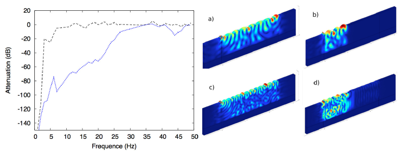
The effect of the clamped columns is most unequivocally seen by looking at the transmission spectra, that is the transmission computed at the soil/PML computational interface at the opposite side of the columns from the line source normalised by the amplitude of the source. The left hand panel of Fig. 5 shows very clearly that the fields are highly attenuated beneath the cut-off frequencies of each case, at and Hz respectively. The vertical scale is in decibels and so this represents the attenuation that would be seen, and in the clamped column case this is for just four clamped columns and is highly effective at blocking incoming waves. This is further exemplified by examining the physical fields as shown in Fig. 5 (a,c) for the clamped bedrock and (b,d) for the idealised clamped, perfectly immovable, columns. The effect of the columns is clearly seen in the fields with almost perfect reflection at the frequencies illustrated.
The results above are not physically realisable as no columns can be completely fixed and rigid all along their length (i.e. zero displacement on all of its boundaries); this provides an ideal upper bound on the possible efficiency of this design, but it is highly encouraging that clamped columnar structures could, at least, achieve part of this behaviour.
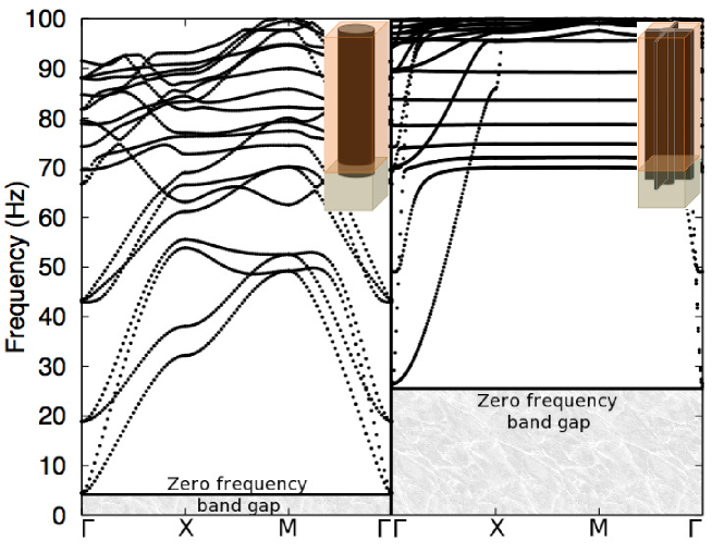
We now turn to realistic designs using illustrative columnar materials and geometries. We choose two examples and treat them in detail, first cylindrical columns of steel (density 7850 kg/m3, Poisson ratio 0.33), m in diameter, in a soil layer of m and bedrock of depth m; the columns are clamped to the bedrock but otherwise free to vibrate and interact with the soil and bedrock. For an infinite array placed at the vertices of a square array (of pitch m) the dispersion curves are shown in Fig. 6(a). It is clear that this has a zero-frequency stop-band up to Hz, which is not dramatic in extent but is none the less an improvement over the unstructured soil. It is, however, far from the optimal case shown in Fig. 3.
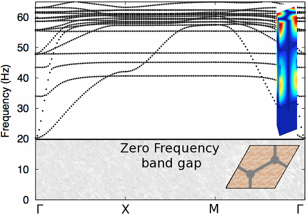
It is well known in the phononic crystal community that very broad band gaps can be designed by the use of cross-shaped inclusions [66], reminiscent of lattice models [67], so we utilise this shape here and further augment this by linking the columns. We consider a cross-shaped inclusion having the same cross-sectional area as the cylinder thereby comparing inclusions that have the same filling fraction. In this second configuration we take a cylindrical column of radius m and each column is then linked to its nearest neighbours by struts (long steel plates of m in thickness), see Fig. 6(b), and this also gives the columns a structural link to its neighbours. This additional reinforcement then leads to a dramatic enhancement in the protected frequency range which is now up to Hz. The dispersion curves of Fig. 6 are for an infinite array and do not reveal the potential efficiency of the design, for this we need the transmission spectra.
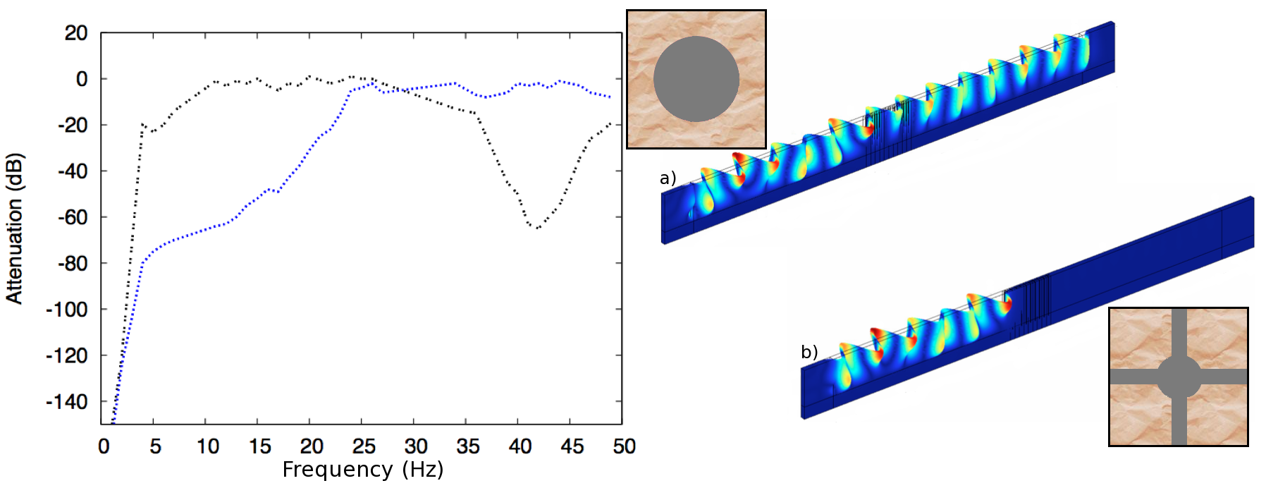
We consider both shear wave and Rayleigh wave incidence, as they have different character. Shear wave incidence is illustrated in Fig. 7 that shows the attenuation of the clamped cylinders and the clamped cross-shaped inclusions; the latter clearly perform much better and the attenuation is strongly enhanced below Hz. Notably this performance is for normal incidence upon a finite array only four columns deep, and improves further if the number of columns is increased. Movies constructed using the time harmonic solutions to show the time evolution of an incoming wave incident upon the columns are shown in the supplementary material. As an aside in Fig. 7 there is a dip in the transmission spectra for the clamped cylindrical columns at approximately 40 Hz which is due to the polarisation of the source and its interaction with the phononic crystal; this can be identified in Fig. 12A when taking into account the polarization state of shear waves.
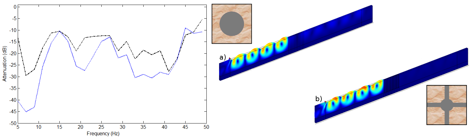
Rayleigh wave incidence is illustrated in Fig. 8 showing again attenuation of the clamped cylinders and the clamped cross-shaped inclusions and the associated displacement fields. The attenuation is not as dramatic as for shear waves due to the stronger coupling of Rayleigh waves into the structure and the finite structure as a whole can vibrate, i.e. the signal at 15 Hz, none the less strong attenuation is achieved for low frequencies.
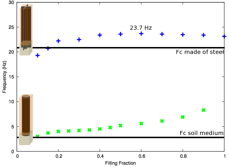
We now address the issue of whether there is an optimal filling fraction. In Fig. 9 we show the upper extent of the zero frequency band-gap for the cross-like inclusions and cylindrical inclusions. In the latter case the upper extent increases monotonically as the filling fraction (also called the soil substitution in the civil engineering literature) increases, as one would expect. For the cross-like inclusion there is a non-monotonic behaviour, all be it very gradual, with a maximum for a filling faction of around . In practical terms, a soil substitution rate beyond to percent is quite substantial in civil engineering due to cost concerns, and in practice the smaller filling fractions are more relevant.
It is natural, of course, given that we have presented in detail a design on a square lattice to consider whether changing the underlying lattice structure to another Bravais lattice creates fundamental changes. It does not, it alters the detail of the extent of the zero frequency band gap but not the physics behind this. As a further illustration we show, in Fig. 10, the dispersion curves for the steel columns (radius 0.3 m and buried 80 cm in the bedrock) placed on a honeycomb lattice with plate attachments along the honeycomb. Again one notes an extensive zero frequency bandgap extending up to 20 Hz, thus there is no specific advantage of using a honeycomb, instead of square, array.
A key point of the design, further emphasised in [68], is the burying of columns in the bedrock and connectivity between columns and to demonstrate how important this is we consider an array of horizontal steel plates of thickness 0.2 m that splits the soil layer into a laminate structure and a column of radius 0.3 m; the band diagrams for this structure are shown in Fig. 11 that also show the polarization (along ) defined as
| (6) |
where the triple integral is over the periodic cell with m the array pitch, m the soil depth and the volume of the cell (note that we checked the displacement field vanishes in the bedrock). Here there is no zero frequency band gap with the dispersion curves always passing through the origin, however there are some interesting features observable in this diagram. For instance, there are pronounced changes of curvature in the lower bands that may be of interest and as one increases the lamination the regions of wavenumber space for which there is propagation shrink.
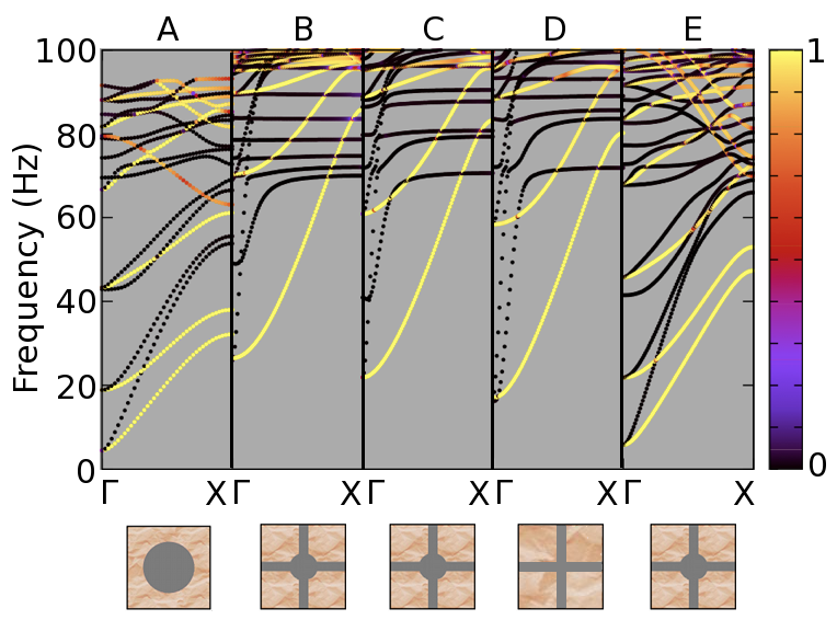
Finally, we investigate the sensitivity of the upper-extent of the zero-frequency band gap to attachment in the bedrock and to modifying the square lattice structure of a steel rod attached to its neighbours by stell plates. We do this in Fig. 12 and show the dispersion cuves only in the , that is for normal propagation to an array, and consider 5 cases: A, is the steel column of radius m of Fig. 6(a) buried cm in bedrock showing a small zero-frequency band-gap, B, is the reference case of the steel column of radius m joined to its neighbours in a square lattice, buried cm of Fig. 6(b) and sharing the same filling fraction as A. Panels C and D are not buried in the rock and merely are joined at the soil / bedrock interface to the bedrock and then have the central steel column absent respectively; the upper extent of the band-gap decreases. E goes one stage further and decouples the joining plates at the edges of the periodic cell and then the band-gap width decreases dramatically. It is clear that the combination of having the steel column, buried in the bedrock, and the coupling of each column to its neighbours via the steel plates is essential to obtain the broad ultra-low frequency stop-bands.
3 Discussion
In Geotechnics, so-called composite soils made of inclusions inserted in a matrix of soil are mainly developed using a pseudo-static analysis; the dynamic loading is converted into an equivalent static loading and the objective is to obtain a higher value of Young’s modulus or shear modulus G (or ) in order to reduce the deformation of the soil-deep foundation system [69, 70]. Homogenization techniques have been also applied to composite soils [71, 72] and recently developed for dynamic loading [73]. The emerging field of seismic metamaterials, based on wave physics, enables us to revisit several longstanding problems of earthquake protection from this fully dynamic point of view.
In this vein, we have considered here how one could use these physics-based ideas to protect specific areas from low-frequency vibration. We have demonstrated, conclusively, that it is possible to design realistic seismic metamaterial devices, in the sense of the structures that form the material being subwavelength and in the limit of small strains such that we have linear elastic conditions. The desired performance is achieved by creating zero-frequency stop-bands using clamping of columns to underlying bedrock. Clearly the challenge is now to build such structures in the spirit of [40] and we anticipate that these results will motivate large-scale experiments to verify this since there are potential applications in seismic defence structures [68]. It is notable that zero-frequency stop-bands will arise in other areas of physics whenever periodic arrays of inclusions have zero field, i.e. Dirichlet data, on their boundary see for instance, [74], in the context of electromagnetic waves or [75] for clamped inclusions in full vector elasticity. One can anticipate this, following [74] any Floquet-Bloch eigenvalue problem involving inclusions with zero Dirichlet data on part of their boundary, will display zero frequency stop-bands, since the existence of an eigenfield associated with a zero frequency would imply by the maximum principle that the eigenfield is null everywhere. Therefore, any wave (electromagnetic, acoustic, hydrodynamic, elastodynamic) will be prohibited to propagate within a periodic structure at very low frequencies provided inclusions can be modelled with zero Dirichlet data (e.g. infinite conducting inclusions in the case of electromagnetics and clamped inclusions in the case of elastodynamics).
Although we have concentrated here on the lowest dispersion curve, at high frequencies, the dispersion curves and asymptotics based around generating dynamic effective media [75, 76, 77] suggest that interesting features will also occur. These include ultra-directivity whereby a periodically pinned plate behaves like an extremely anisotropy effective medium at frequencies associated with flat bands on dispersion diagrams [51]. This feature of a flat band can be seen in Fig. 1(a), for both the Kirchhoff-Love thin plate limit and the full vector elastic model. Other interesting features seen in Fig. 1(a) include coalescing dispersion curves and inflection points (the latter being associated with hyperbolic-type effective properties [51]). Interestingly for the Rayleigh-like waves that occur in thick plates with unmovable (clamped) inclusions, one expects similar features to occur, and indeed one can see in Fig. 3 that the dispersion curves display flat bands and inflection points and so similar interesting and useful effects will occur at higher frequencies.
Finally, we note that we assumed a linear elastic model for soil and columns of concrete, however, the former has visco-elastic features, that could also be implemented e.g. via a Kelvin-Voigt contact condition at the soil-column interfaces. Intuitively, we expect that such a model would reduce the local resonances, and the extremely high damping seen in Fig. 5 and 8 around certain frequencies, would be less pronounced.
Acknowledgements
R.C. thanks the EPSRC for their support through research grants EP/I018948/1, EP/L024926/1, EP/J009636/1. S.G. and Y.A. are thankful for an ERC starting grant (ANAMORPHISM) that facilitated the collaboration with Imperial College London.
We also thank A. Diatta for his help in the implementation of Cartesian PMLs in elasticity.
References
References
- [1] R. Reitherman. Earthquakes and Engineers: An International History. ASCE Press, Reston, VA, 2012.
- [2] S. Brûlé, E. Javelaud, and M. Marchand. Chimneys health monitoring during a nearby heavy dynamic compaction site. Journées Nationales de Géotechnique et de Géologie de l’Ingénieur, pages 919–926, 2012.
- [3] A. Chopra. Dynamics of Structures. Theory and Applications to Earthquake Engineering. Pearson Prentice-Hall, 2012.
- [4] J. D. Joannopoulos, S. G. Johnson, J. N. Winn, and R. D. Meade. Photonic Crystals, Molding the Flow of Light. Princeton University Press, Princeton, second edition, 2008.
- [5] F. Zolla, G. Renversez, A. Nicolet, B. Kuhlmey, S. Guenneau, and D. Felbacq. Foundations of photonic crystal fibres. Imperial College Press, London, 2005.
- [6] S. John. Strong localization of photons in certain disordered dielectric superlattices. Phys. Rev. Lett., 58:2486–2489, 1987.
- [7] E. Yablonovitch. Inhibited spontaneous emission in solid-state physics and electronics. Phys. Rev. Lett., 58:2059, 1987.
- [8] C. Wilcox. Theory of Bloch waves. J. Anal. Math., 33:146–167, 1978.
- [9] C. Conca, J. Planchard, and M. Vanninathan. Fluids and Periodic structures. Res. Appl. Math., Masson, Paris, 1995.
- [10] J. Gazalet, S. Dupont, J.C. Kastelik, Q. Rolland, and B. Djafari-Rouhani. A tutorial survey on waves propagating in periodic media: Electronic, photonic and phononic crystals. perception of the bloch theorem in both real and fourier domains. Wave Motion, 50:619–654, 2013.
- [11] A. L. Chen and Y. S. Wang. Study on band gaps of elastic waves propagating in one-dimensional disordered phononic crystals. Physica B, 392:369–378, 2007.
- [12] A. Figotin and I. Vitebskiy. Slow light in photonic crystals. Waves Random Complex Media, 16:293–392, 2006.
- [13] J. B. Pendry. Negative refraction makes a perfect lens. Phys. Rev. Lett., 85:3966–3969, 2000.
- [14] S. A. Ramakrishna. Physics of negative refractive index materials. Rep. Prog. Phys., 68:449–521, 2005.
- [15] I.V. Iorch, I.S. Mukhin, I.V. Shadrivov, P.A. Belov, and Y.S. Kivshar. Hyperbolic metamaterials based on multilayer graphene structures. Phys. Rev. B, 87:075416–6, 2013.
- [16] J.B. Pendry, D. Schurig, and D.R. Smith. Controlling electromagnetic fields. Science, 2006.
- [17] U. Leonhardt. Optical conformal mapping. Science, 312:1777–1780, 2006.
- [18] E. N. Economou and M. M. Sigalas. Classical wave propagation in periodic structures: Cermet versus network topology. Phys. Rev. B, 48:13434–13438, 1993.
- [19] R. Martinez-Sala, J. Sancho, J.V. Sanchez, V. Gomez, J. Linares, and F. Meseguer. Sound attenuation by sculpturel. Nature, 378:241, 1995.
- [20] X. Hu and C. T. Chan. Refraction of water waves by periodic cylinder arrays. Phys. Rev. Lett., 95:154501, 2005.
- [21] M. Farhat, S. Enoch, S. Guenneau, and A.B. Movchan. Broadband cylindrical acoustic cloak for linear surface waves in a fluid. Phys. Rev. Lett., 101:1345011, 2008.
- [22] G. Dupont, O. Kimmoun, B. Molin, S. Guenneau, and S. Enoch. Numerical and experimental study of an invisibility carpet in a water channel. Phys. Rev. E, 91:023010, 2015.
- [23] C.P. Berraquero, A. Maurel, P. Petitjeans, and V. Pagneux. Experimental realization of a water-wave metamaterial shifter. Phys. Rev. E, 88:051002(R), 2013.
- [24] D. V. Evans and R. Porter. Penetration of flexural waves through a periodically constrained thin elastic plate floating in vacuo and floating on water. J. Engng. Math., 58:317–337, 2007.
- [25] D.J. Colquitt, R.V. Craster, T. Antonakakis, and S. Guenneau. Rayleigh-Bloch waves along elastic diffraction gratings. Proc. R. Soc. A, 471:20140465, 2015.
- [26] S. Maier. Plasmonics: Fundamentals and Applications. Springer, London, 2010.
- [27] J. B. Pendry, L. Martin-Moreno, and F. J. Garcia-Vidal. Mimicking surface plasmons with structured surfaces. Science, 305:847–848, 2004.
- [28] S. Benchabane, A. Khelif, J. Y. Rauch, L. Robert, and V. Laude. Evidence for complete surface wave band gap in a piezoelectric phononic crystal. Phys. Rev. E, 73:065601, 2006.
- [29] S. Benchabane, O. Gaiffe, G. Ulliac, R. Salut, Y. Achaoui, and V. Laude. Observation of surface-guided waves in holey hypersonic phononic crystal. Applied Physics Letters, 98:171908, 2011.
- [30] A. Khelif, Y. Achaoui, S. Benchabane, V. Laude, and B. Aoubiza. Locally resonant surface acoustic wave band gaps in a two-dimensional phononic crystal of pillars on a surface. Phys. Rev. B, 81:214303, 2010.
- [31] Y. Achaoui, A. Khelif, S. Benchabane, L. Robert, and V. Laude. Experimental observation of locally-resonant and bragg band gaps for surface guided waves in a phononic crystal of pillars. Physical Review B, 10:104201, 2011.
- [32] M. A. Al-Lethawe, M. Addouche, A. Khelif, and S. Guenneau. All-angle negative refraction for surface acoustic waves in pillar-based two-dimensional phononic structures. New J. Phys., 14:123030, 2012.
- [33] J. Pierre, O. Boyko, L. Belliard, J.O. Vasseur, and B. Bonello. Negative refraction of zero order flexural lamb waves through a two-dimensional phononic crystal. Applied Physics Letters, 97:121919, 2010.
- [34] M. Dubois, M. Farhat, E. Bossy, S. Enoch, S. Guenneau, and P. Sebbah. Flat lens for pulse focusing of elastic waves in thin plates. Applied Physics Letters, 103:071915, 2013.
- [35] T. Antonakakis, R.V. Craster, and S. Guenneau. Moulding and shielding flexural waves in elastic plates. Europhysics Letters, 105:54004, 2014.
- [36] B. Graczykowski, M. Sledzinska, F. Alzina, J. Gomis-Bresco, J. S. Reparaz, M. R. Wagner, and C. M. Sotomayor Torres. Phonon dispersion in hypersonic two-dimensional phononic crystal membranes. Phys. Rev. B, 91:075414, 2015.
- [37] N. Boechler, J. K. Eliason, A. Kumar, A. A. Maznev, K. A. Nelson, and N. Fang. Interaction of a contact resonance of microspheres with surface acoustic waves. Phys. Rev. Lett., 111:036103, 2013.
- [38] A. Colombi, P. Roux, and M. Rupin. Sub-wavelength energy trapping of elastic waves in a meta-material. Journal of the Acoustic Society of America, 136:104201, 2014.
- [39] F. Meseguer, M. Holgado, D. Caballero, N. Benaches, J. Sanchez-Dehesa, C. Lopez, and J. Llinares. Rayleigh-wave attenuation by a semi-infinite two-dimensional elastic-band-gap crystal. Phys. Rev. B, 59:12169, 1999.
- [40] S. Brûlé, E. H. Javelaud, S. Enoch, and S. Guenneau. Experiments on seismic metamaterials: Molding surface waves. Phys. Rev. Lett., 112:133901, 2014.
- [41] M. Miniaci, A. Krushynska, F. Bosia, and N. M. Pugno. Large scale mechanical metamaterials as seismic shields. New J. Phys., 18:083041, 2016.
- [42] S. Krodel, N. Thome, and C. Daraio. Wide band-gap seismic metastructures. Extreme Mech. Lett., 4:111–117, 2015.
- [43] Y. Achaoui, B. Ungureanu, S. Enoch, S. Brule, and S. Guenneau. Seismic waves damping with arrays of inertial resonators. Extreme Mechanics Letters, 8:30–37, 2016.
- [44] G. Finocchio, O. Casablanca, G. Ricciardi, U. Alibrandi, F. Garesci, M. Chiappini, and B. Azzerboni. Seismic metamaterials based on isochronous mechanical oscillators. Appl. Phys. Lett., 104:191903, 2014.
- [45] A. Colombi, P. Roux, S. Guenneau, P. Gueguen, and R. V. Craster. Forests as a natural seismic metamaterial: Rayleigh wave bandgaps induced by local resonances. Scientific Reports, 6:19238, 2016.
- [46] A. Colombi, D. Colquitt, P. Roux, S. Guenneau, and R. V. Craster. A seismic metamaterial: The resonant metawedge. Scientific Reports, 6:27717, 2016.
- [47] L. D. Landau and E. M. Lifshitz. Theory of elasticity. Pergamon Press, 2nd edition, 1970.
- [48] K. F. Graff. Wave motion in elastic solids. Oxford University Press, 1975.
- [49] J. D. Achenbach. Wave propagation in elastic solids. Amsterdam: North-Holland., 1984.
- [50] L. R. F. Rose and C. H. Wang. Mindlin plate theory for damage detection: source solutions. J. Acoust. Soc. Am., 116:154–171, 2004.
- [51] G. Lefebvre, T. Antonakakis, Y. Achaoui, R. V. Craster, S. Guenneau, and P. Sebbah. Unveiling extreme anisotropy in elastic structured media. submitted: https://arxiv.org/abs/1610.04884.
- [52] COMSOL User’s Guide version 5.2, 2016. http://www.comsol.com/.
- [53] C. Kittel. Introduction to solid state physics. John Wiley & Sons, New York, 7th edition, 1996.
- [54] D. Colquitt A. Colombi, R. V. Craster, P. Roux, and S. Guenneau. Seismic metasurfaces: Sub-wavelength resonators and rayleigh wave interaction. Journal of the Mechanics and Physics of Solids, 99:379–393, 2016.
- [55] S. Brûlé, S. Enoch, S. Guenneau, and R. V. Craster. Handbook of Metamaterials, chapter Seismic Metamaterials: Controlling surface Rayleigh waves using analogies with electromagnetic metamaterials. World Scientific, 2017. In Press.
- [56] J.F. Semblat and A. Pecker. Waves and vibrations in soils: earthquakes, traffic, shocks, construction works. IUSS Press, Pavia, 2009.
- [57] P.G. Ciarlet. Mathematical elasticity. Volume II: Theory of plates. North Holland, 1997.
- [58] A. Nicolet, S. Guenneau, C. Geuzaine, and F. Zolla. Modeling of electromagnetic waves in periodic media with finite elements. Jour. Comp. App. Math., 168:321–329, 2004.
- [59] R. V. Craster, J. Kaplunov, and A. V. Pichugin. High frequency homogenization for periodic media. Proc R Soc Lond A, 466:2341–2362, 2010.
- [60] A. Bensoussan, J.L. Lions, and G. Papanicolaou. Asymptotic analysis for periodic structures. North-Holland, Amsterdam, 1978.
- [61] S. Guenneau, C. G. Poulton, and A. B. Movchan. Oblique propagation of elecromagnetic and elastodynamic waves for an array of cylindrical fibres. Proc. Roy. Soc. Lond. A, 459:2215–2263, 2003.
- [62] J. M. Harrison, P. Kuchment, A. Sobolev, and B. Winn. On occurrence of spectral edges for periodic operators inside the Brillouin zone. J. Phys. A - Math, 40:7597–7618, 2007.
- [63] R. V. Craster, T. Antonakakis, M. Makwana, and S. Guenneau. Dangers of using the edges of the Brillouin zone. Phys. Rev. B, 86:115130, 2012.
- [64] Y. Brule, B. Gralak, and G. Demesy. Calculation and analysis of the complex band structure of dispersive and dissipative two-dimensional photonic crystals. Journal of the Optical Society of America. B, 33:691, 2016.
- [65] A. Diatta, M. Kadic, M. Wegener, and S. Guenneau. Scattering problems in elastodynamics. Physical Review B, 94:100105, 2016.
- [66] Y-F. Wang, Y-S. Wang, and X-X. Su. Large bandgaps of two-dimensional phononic crystals with cross-like holes. J. Appl. Phys., 110:113520, 2011.
- [67] P. G. Martinsson and A. B. Movchan. Vibrations of lattice structures and phononic band gaps. Q. Jl. Mech. Appl. Math., 56:45–64, 2003.
- [68] Y. Achaoui, T. Antonakakis, S. Brulé, R. Craster, S. Enoch, and S. Guenneau. Seismic defence structures. Patent, 2016.
- [69] AFPS and CFMS. Procédés d’amélioration et de renforcement de sols sous action sismique. Guide technique, Presses des Ponts, 2012.
- [70] A. Pecker and P. Teyssandier. Conception parasismique du pont de rion-antirion. 19ème Congrès Français de Mécanique, Marseille, 24-28 août, 2009.
- [71] P. De Buhan. Approche fondamentale du calcul à la rupture des ouvrages en sols renforcés. Thèse de Doctorat d’Etat, Université Pierre et Marie Curie, Paris, 1986.
- [72] M. Guéguin. Approche par une méthode d’homogénéisation du comportement des ouvrages en sols renforcés par colonnes ou tranchées. Thèse de Troisième Cycle, Université Paris Est, Paris, 2014.
- [73] V. Nguyen. Analyse sismique des ouvrages renforcés par inclusions rigides à l’aide d’une modélisation multiphasique. Thèse de Troisième Cycle, Université Paris Est, Paris, 2014.
- [74] C.G. Poulton, L.C. Botten, R.C. McPhedran, N.A. Nicorovici, and A.B. Movchan. Non-commuting limits in electromagnetic scattering: an asymptotic analysis for an array of highly conducting inclusions. SIAM Journal on Applied Mathematics, 61:1706–1730, 2001.
- [75] T. Antonakakis, R.V. Craster, and S. Guenneau. Homogenisation for elastic photonic crystals and dynamic anisotropy. Journal of the Mechanics and Physics of Solids, 71:84–96, 2014.
- [76] J.L. Auriault and C. Boutin. Long wavelength inner-resonance cut-off frequencies in elastic composite materials. International Journal of Solids and Structures, 49:3269–3281, 2012.
- [77] C. Boutin, A. Rallu, and S. Hans. Large scale modulation of high frequency waves in periodic elastic composites. Journal of the Mechanics and Physics of Solids, 70:362–381, 2014.
Appendix A Summary of material values and parameters
For clarity and convenience we summarize here the choices of material and parameters chosen in the text.
| parameters | soil | bedrock | steel columns | steel plates |
| depth | 15 m | 5 m | m | |
| Square pitch | 2 m | |||
| Honeycomb pitch | 2 m | |||
| Plate thickness | m | |||
| column radius | m (Figs. 3b, 4,5bd) | |||
| m (Figs. 6b,7b,8b,10,11,12bce) | ||||
| m (Figs. 6a,12a) | ||||
| Young modulus (GPa) | 0.153 | |||
| Poisson’s ratio | ||||
| Density (kg/) |